Mac computer, screen, GitLab, HTML site, patience.
Introduction
This week I learned how to use KiCad to design PCB board. I used it as a first draft for the PCB board for my final project. The board was then milled out and I soldered the electronic pieces in place. The XIAO-ESP32-C3 was programmed using Arduino programing. *
The group project was to measure using a multimeter.
Projects
KiCad: Schematic Editor
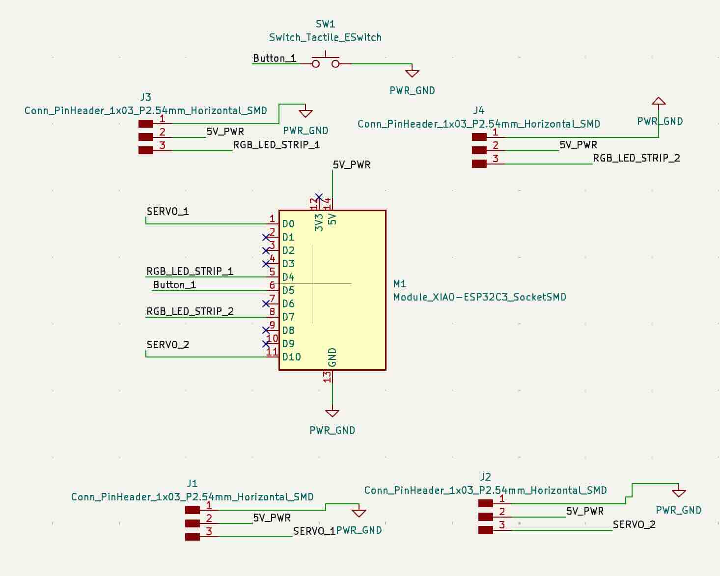
I put all the electronic parts into the schematic editor and connected between them. Then I used the PCB editor to align the parts and design the board according to my needs. The board was designed with two servos and two LED strips. The Servos will be used to move the wings and the LED will be attached to the wings. I had never used Electronics Design Automation (EDA) before and I learned to make the board and needed circuts from scratch.
Since this was my first time using KiCad I got some help from my instructor. He went over the basic commands and how to add the Fab components library, and designing a simple PCB board.
Item list
Name
Quantity
Item1
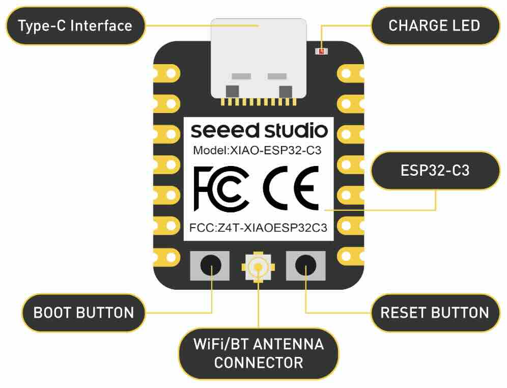
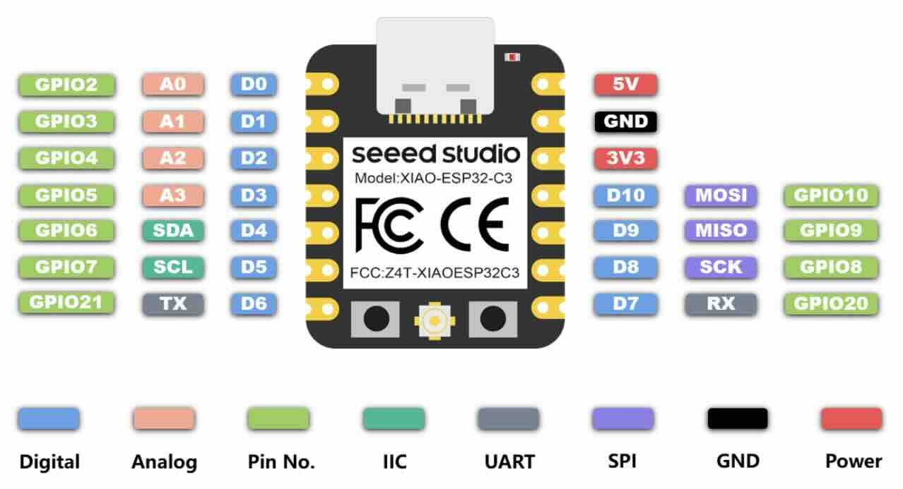
XIAO ESP32-C3.
1x
Item2
Female Pin Header 1x3 2.54mm.
4x
Item3
Female Pin Header 1x7 2.54mm.
2x
Item4
1x7 Single Row Pin Header Connector.
2x
Item5
Button 6.0x6.0mm.
1x
Item6
RGB LED STRIP .
2x
Item7
SERVO.
2x
KiCad: PCB Editor
KiCad: 3D Viewer
I used the schematic editor and PCB editor in KiCad to design the board. I ended up tinkering with the program until I got the board to work. I had a problem come up where two of the line were too close together so I used a screwdriver and cut between them to prevent to from connecting.
Here is a brief overview of how to set up the DRC in KiCad. Go to preferences and select design rules or DRC rules. You sill find various tabs for different design rule categories. They will include clearance, with, via, etc. Review the default rule value and customize them. You do that by clicking on the category tab and adjusting to values to your needs. Fo Example in the clearance tab, you can set up the minimum allowed clearance between different objects like tracks, pads and vias. When you have adjusted everything to your need you run check or check DRC (button). KiCad will then analyze your design based on the defined rules and provide a report on any error or violations. Then you can alter or fix those errors by adjusting your design according to them. That can mean you will have to move components, modify track width or adjusting clearances. After adjusting the design run DRC again until the board passes without errors.
Changed the file so it could be cut out Roland. I opened the file in Inkscape and made the white box to put behind thefile. When that was doneI exported the files and made sure the DPI was set to 1000 then I moved the top layer to see only the while box, exported the white box and made sure the DPI was set to 1000. Then I moved both files to my USB drive. then I followed the steps described in week 4.
Roland modela mdx-20: Board
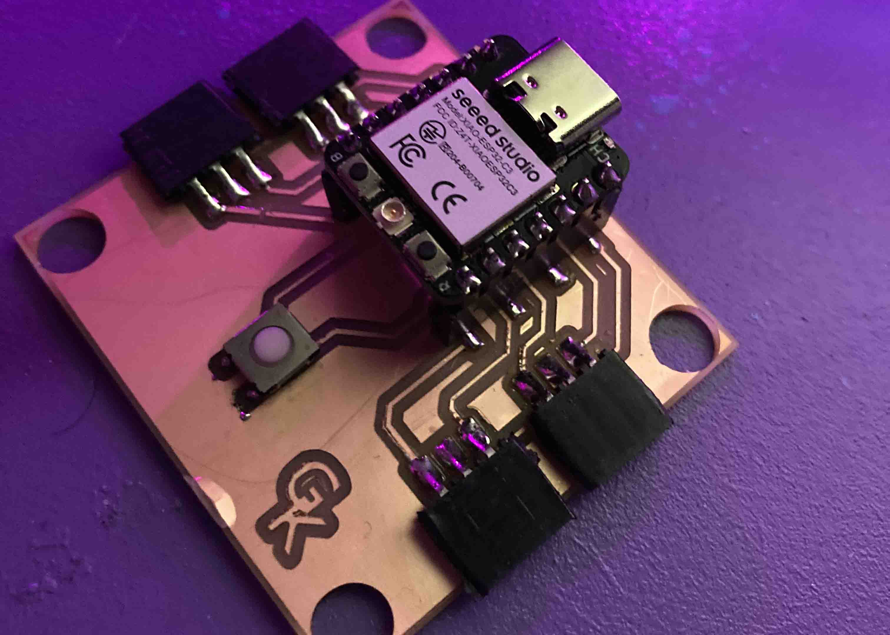
Milled out the trace and cut for the board in Roland. Copper plate. I goth help with putting double sided tape on the back of the copper board. The double sided tap needed to lie next to one another but not overlap. Removed the film of the double sided tape and attached the copper board to the copper board that is attached to the Roland Roland_modela_mdx-20 to make sure the board doesnt warp. Spray the board with rubbing alcohol to clean off any fingerprind or dust.
Board finished. View of finished sodering. Needed to cut the link between one pin because they were too close.
programming: Board
Arduino Programming used for board.
plexiLamp_multipleLightThemes
#include
#ifdef __AVR__
 #include  // Required for 16 MHz Adafruit Trinket
#endif

#define PIXEL_PIN    D7
#define BUTTON_PIN   D5
#define PIXEL_COUNT  10

Adafruit_NeoPixel strip(PIXEL_COUNT, PIXEL_PIN, NEO_GRB + NEO_KHZ800);

bool modeChanged = false;
int mode = 0; // 0 for flame, 1 for rainbow, 2-8 for solid colors, 9 for off
unsigned long lastDebounceTime = 0;  // the last time the output pin was toggled
unsigned long debounceDelay = 50;    // the debounce time; increase if the output flickers

void setup() {
  Serial.begin(9600);

  strip.begin();
  strip.show();
  pinMode(BUTTON_PIN, INPUT_PULLUP);
}

void loop() {
  int reading = digitalRead(BUTTON_PIN);

  // Check button state and debounce
  if (reading == LOW) {
    if ((millis() - lastDebounceTime) > debounceDelay) {
      if (!modeChanged) {
        mode++;
        modeChanged = true;
        if (mode > 9) { // Update the maximum mode number
          mode = 0;
        }
        Serial.print("Mode changed to: ");
        Serial.println(mode);
      }
      lastDebounceTime = millis(); // Reset the debouncing timer
    }
  } else {
    modeChanged = false; // Reset mode changed flag when button is not pressed
  }

  switch (mode) {
    case 0:
      Serial.println("Fire");

      fireAnimation(75);
      break;
    case 1:
      Serial.println("Rainbow");

      rainbowAnimation();
      break;
    default:
      if (mode >= 2 && mode <= 8) {
        Serial.println("Colors");

        solidColor(mode - 2);
      } else if (mode == 9) {
        Serial.println("Off");

        turnOffLights();
      }
      break;
  }
}

void fireAnimation(int wait) {
  // First loop: Set the initial color for each LED
  for (int i = 0; i < strip.numPixels(); i++) {
    int r = random(150, 255); // More red for a fiery color
    int g = random(0, 85);    // Random amount of green to vary between red and yellow
    int b = 0;                // No blue component for fire

    strip.setPixelColor(i, r, g, b);
  }

  // Second loop: Apply the flicker effect
  for (int i = 0; i < strip.numPixels(); i++) {
    uint32_t color = strip.getPixelColor(i);
    int r = (color >> 16) & 0xFF;
    int g = (color >> 8) & 0xFF;

    // Random flicker effect
    int flicker = random(0, 150);
    r = max(0, r - flicker);
    g = max(0, g - flicker);

    strip.setPixelColor(i, r, g, 0);
  }

  strip.show();
  delay(wait);
}

void rainbowAnimation() {
  static unsigned long lastUpdate = 0; // Last update time
  static uint16_t j = 0; // Position in color wheel

  // Update only if the appropriate interval has passed
  if (millis() - lastUpdate > 20) {
    for (int i = 0; i < strip.numPixels(); i++) {
      strip.setPixelColor(i, Wheel((i + j) & 255));
    }
    strip.show();

    j = (j + 1) % 256; // Move to the next position in the color wheel
    lastUpdate = millis(); // Update the last update time
  }
}


// Input a value 0 to 255 to get a color value.
// The colors are a transition r - g - b - back to r.
uint32_t Wheel(byte WheelPos) {
  WheelPos = 255 - WheelPos;
  if(WheelPos < 85) {
    return strip.Color(255 - WheelPos * 3, 0, WheelPos * 3);
  }
  if(WheelPos < 170) {
    WheelPos -= 85;
    return strip.Color(0, WheelPos * 3, 255 - WheelPos * 3);
  }
  WheelPos -= 170;
  return strip.Color(WheelPos * 3, 255 - WheelPos * 3, 0);
}

void solidColor(int color) {
  uint32_t col;

  switch(color) {
    case 0: col = strip.Color(255, 0, 0); break; // Red
    case 1: col = strip.Color(255, 165, 0); break; // Orange
    case 2: col = strip.Color(255, 255, 0); break; // Yellow
    case 3: col = strip.Color(0, 255, 0); break; // Green
    case 4: col = strip.Color(0, 0, 255); break; // Blue
    case 5: col = strip.Color(75, 0, 130); break; // Indigo
    case 6: col = strip.Color(238, 130, 238); break; // Violet
    default: col = strip.Color(0, 0, 0); break; // Off
  }

  for(int i = 0; i < strip.numPixels(); i++) {
    strip.setPixelColor(i, col);
  }
  strip.show();
}

void turnOffLights() {
  for(int i = 0; i < strip.numPixels(); i++) {
    strip.setPixelColor(i, strip.Color(0, 0, 0)); // Turn off this LED
  }
  strip.show();
}
I started by measureing the internal resistance of the multimeter which was about 0.2 ohm
I then measured a resistor
I then measured a capacitor
Then I used the multimeter to test a button
Summary
I based this project on what I learned in week 4. The only that didnt workout according to plan was that I put the traces too close to each other in spot and had to manually cut the link between them. This I will fix in the next version. I also learned that for the LED lights it should have been male pins and not female pin headers. The group project went smoothly but mostly because I had taken a semester in elecronics and that helped a lot.


