Input Devices
Project description
Group Assignment
Probe an input device's analog levels and digital signals.
Assignment
Measure something: add a sensor to a microcontroller board that you have designed and read it.
Probe an input device's analog levels and digital signals.
Measure something: add a sensor to a microcontroller board that you have designed and read it.

Mac computer, screen, GitLab, HTML site, patience, Arduino IDE, Oscilloscope, soldering iron..
This week I had to measure something and add a sensor to a PCB board. I desided to measure oscilloscope to measure the board from the hotdog condiment dispencer. I added a sensor to DHT22 board.

| Name | Quantity | |
|---|---|---|
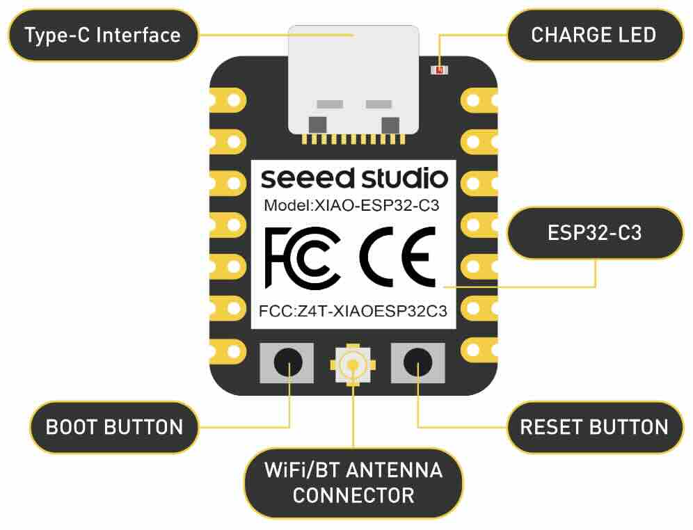
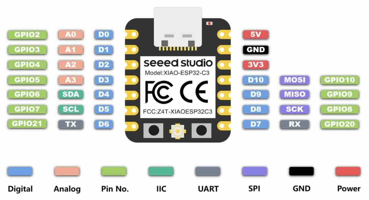
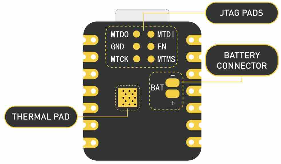
| Item1 | XIAO ESP32-C3. | 1x |
| Item2 | Female Pin Header 1x3 2.54mm. | 4x |
| Item3 | Female Pin Header 1x7 2.54mm. | 2x |
| Item4 | 1x7 Single Row Pin Header Connector. | 2x |
| Item5 | Button 6.0x6.0mm. | 1x |
Board finished. View of finished sodering. Needed to cut the link between one pin because they were too close.

Arduino Programming used for board.
#include
#ifdef __AVR__
 #include  // Required for 16 MHz Adafruit Trinket
#endif

#define PIXEL_PIN    D7
#define BUTTON_PIN   D5
#define PIXEL_COUNT  10

Adafruit_NeoPixel strip(PIXEL_COUNT, PIXEL_PIN, NEO_GRB + NEO_KHZ800);

bool modeChanged = false;
int mode = 0; // 0 for flame, 1 for rainbow, 2-8 for solid colors, 9 for off
unsigned long lastDebounceTime = 0;  // the last time the output pin was toggled
unsigned long debounceDelay = 50;    // the debounce time; increase if the output flickers

void setup() {
  Serial.begin(9600);

  strip.begin();
  strip.show();
  pinMode(BUTTON_PIN, INPUT_PULLUP);
}

void loop() {
  int reading = digitalRead(BUTTON_PIN);

  // Check button state and debounce
  if (reading == LOW) {
    if ((millis() - lastDebounceTime) > debounceDelay) {
      if (!modeChanged) {
        mode++;
        modeChanged = true;
        if (mode > 9) { // Update the maximum mode number
          mode = 0;
        }
        Serial.print("Mode changed to: ");
        Serial.println(mode);
      }
      lastDebounceTime = millis(); // Reset the debouncing timer
    }
  } else {
    modeChanged = false; // Reset mode changed flag when button is not pressed
  }

  switch (mode) {
    case 0:
      Serial.println("Fire");

      fireAnimation(75);
      break;
    case 1:
      Serial.println("Rainbow");

      rainbowAnimation();
      break;
    default:
      if (mode >= 2 && mode <= 8) {
        Serial.println("Colors");

        solidColor(mode - 2);
      } else if (mode == 9) {
        Serial.println("Off");

        turnOffLights();
      }
      break;
  }
}

void fireAnimation(int wait) {
  // First loop: Set the initial color for each LED
  for (int i = 0; i < strip.numPixels(); i++) {
    int r = random(150, 255); // More red for a fiery color
    int g = random(0, 85);    // Random amount of green to vary between red and yellow
    int b = 0;                // No blue component for fire

    strip.setPixelColor(i, r, g, b);
  }

  // Second loop: Apply the flicker effect
  for (int i = 0; i < strip.numPixels(); i++) {
    uint32_t color = strip.getPixelColor(i);
    int r = (color >> 16) & 0xFF;
    int g = (color >> 8) & 0xFF;

    // Random flicker effect
    int flicker = random(0, 150);
    r = max(0, r - flicker);
    g = max(0, g - flicker);

    strip.setPixelColor(i, r, g, 0);
  }

  strip.show();
  delay(wait);
}

void rainbowAnimation() {
  static unsigned long lastUpdate = 0; // Last update time
  static uint16_t j = 0; // Position in color wheel

  // Update only if the appropriate interval has passed
  if (millis() - lastUpdate > 20) {
    for (int i = 0; i < strip.numPixels(); i++) {
      strip.setPixelColor(i, Wheel((i + j) & 255));
    }
    strip.show();

    j = (j + 1) % 256; // Move to the next position in the color wheel
    lastUpdate = millis(); // Update the last update time
  }
}


// Input a value 0 to 255 to get a color value.
// The colors are a transition r - g - b - back to r.
uint32_t Wheel(byte WheelPos) {
  WheelPos = 255 - WheelPos;
  if(WheelPos < 85) {
    return strip.Color(255 - WheelPos * 3, 0, WheelPos * 3);
  }
  if(WheelPos < 170) {
    WheelPos -= 85;
    return strip.Color(0, WheelPos * 3, 255 - WheelPos * 3);
  }
  WheelPos -= 170;
  return strip.Color(WheelPos * 3, 255 - WheelPos * 3, 0);
}

void solidColor(int color) {
  uint32_t col;

  switch(color) {
    case 0: col = strip.Color(255, 0, 0); break; // Red
    case 1: col = strip.Color(255, 165, 0); break; // Orange
    case 2: col = strip.Color(255, 255, 0); break; // Yellow
    case 3: col = strip.Color(0, 255, 0); break; // Green
    case 4: col = strip.Color(0, 0, 255); break; // Blue
    case 5: col = strip.Color(75, 0, 130); break; // Indigo
    case 6: col = strip.Color(238, 130, 238); break; // Violet
    default: col = strip.Color(0, 0, 0); break; // Off
  }

  for(int i = 0; i < strip.numPixels(); i++) {
    strip.setPixelColor(i, col);
  }
  strip.show();
}

void turnOffLights() {
  for(int i = 0; i < strip.numPixels(); i++) {
    strip.setPixelColor(i, strip.Color(0, 0, 0)); // Turn off this LED
  }
  strip.show();
}
The board is from week 10 (Machine week). The board is analog using the oscilloscope to measure varying signals from board, for example the the steper motor. One probe is connected to GND and the other to a output pin for the stepper.

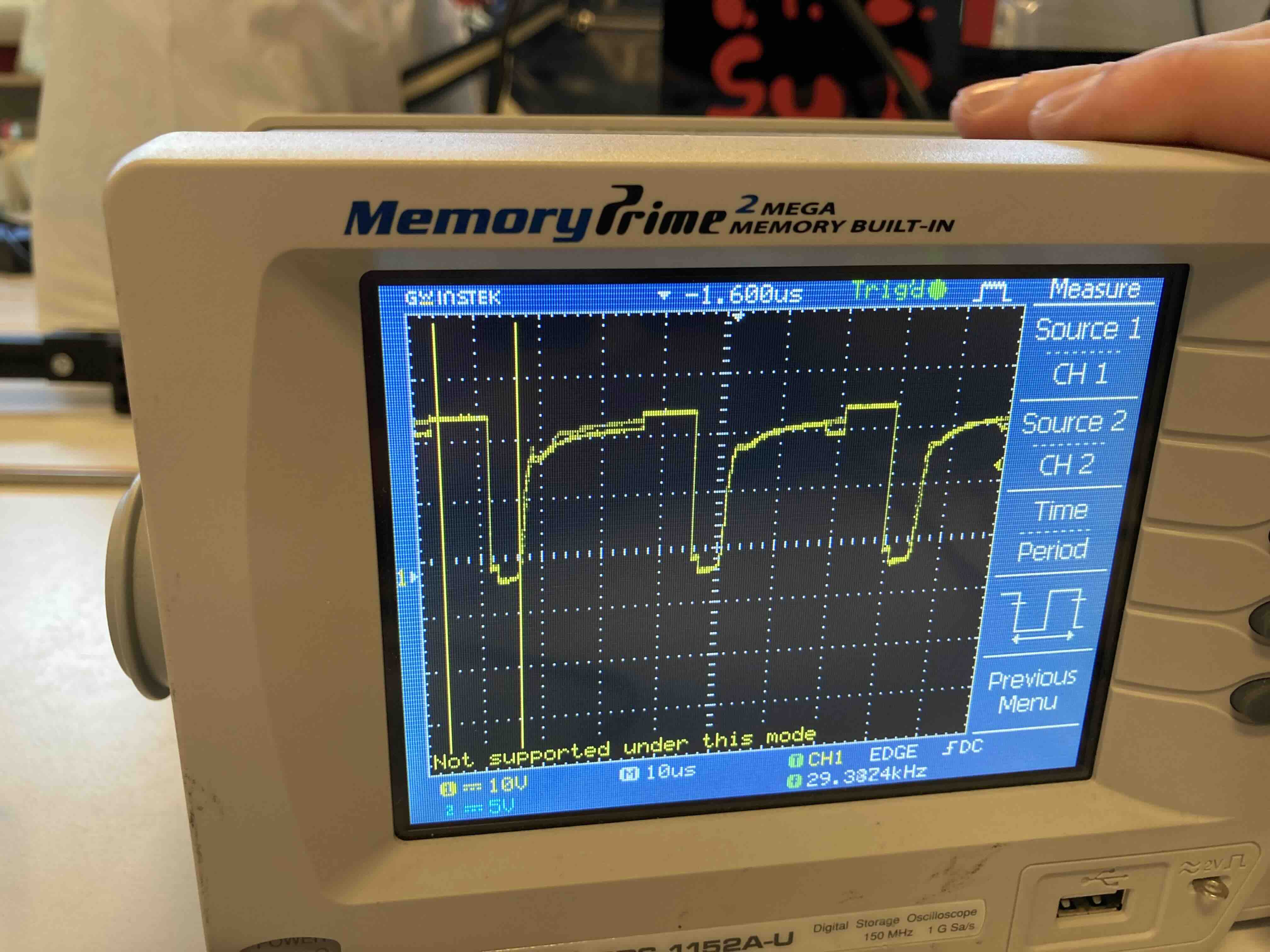
The board is from week 8 (Electronics Design week). The board using the oscilloscope to measure the digital signal to the RGBW led strip.

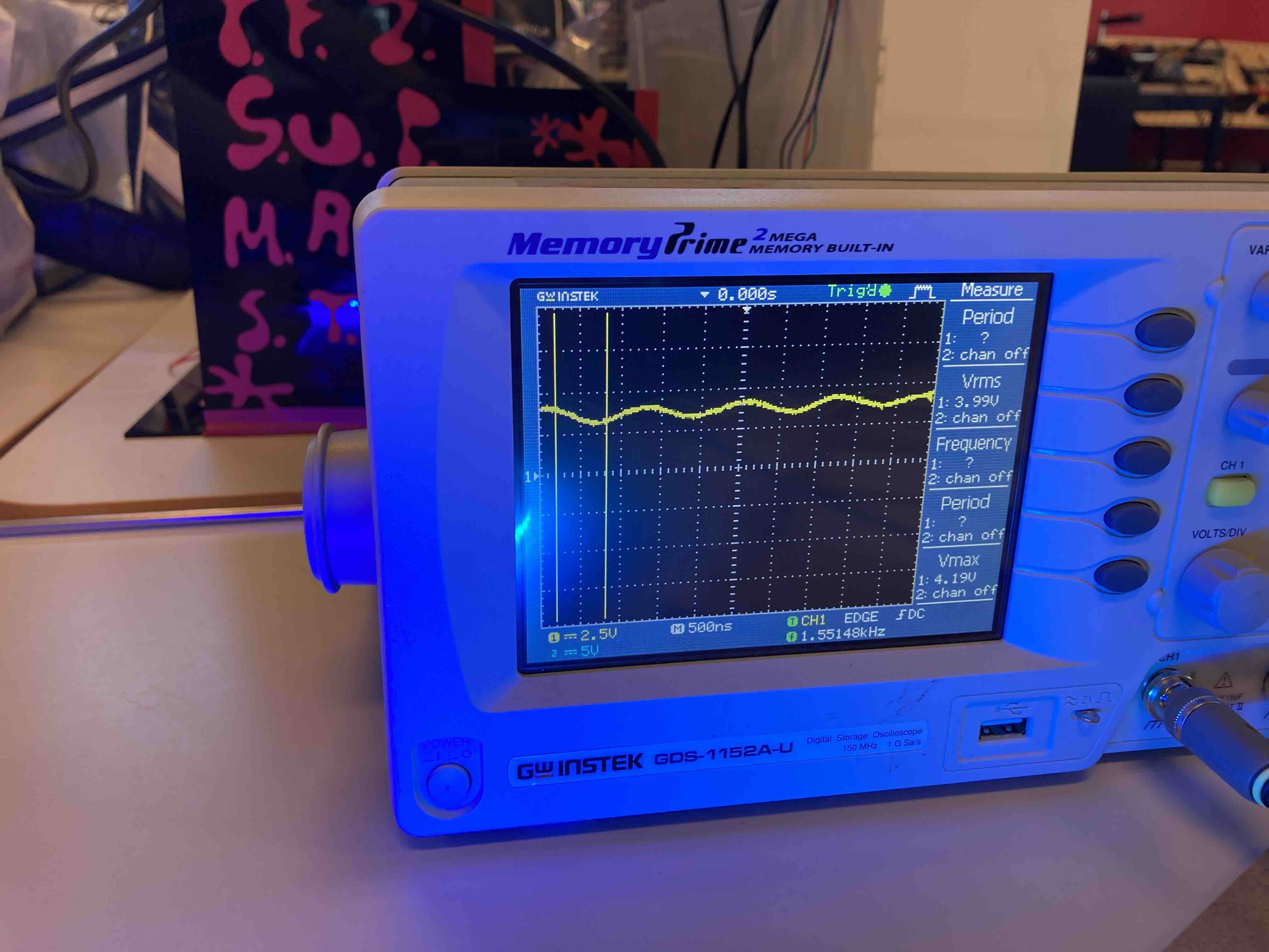
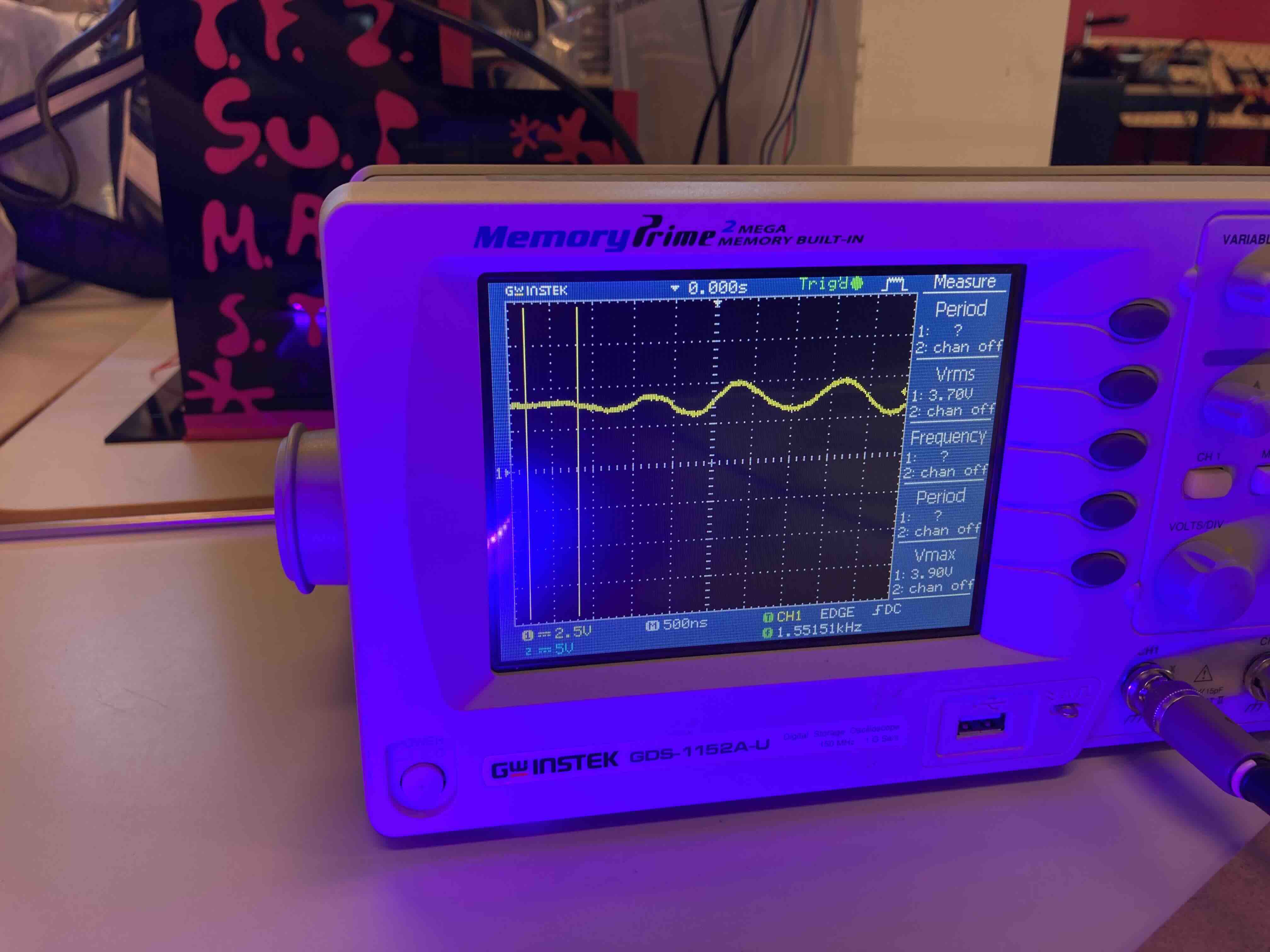
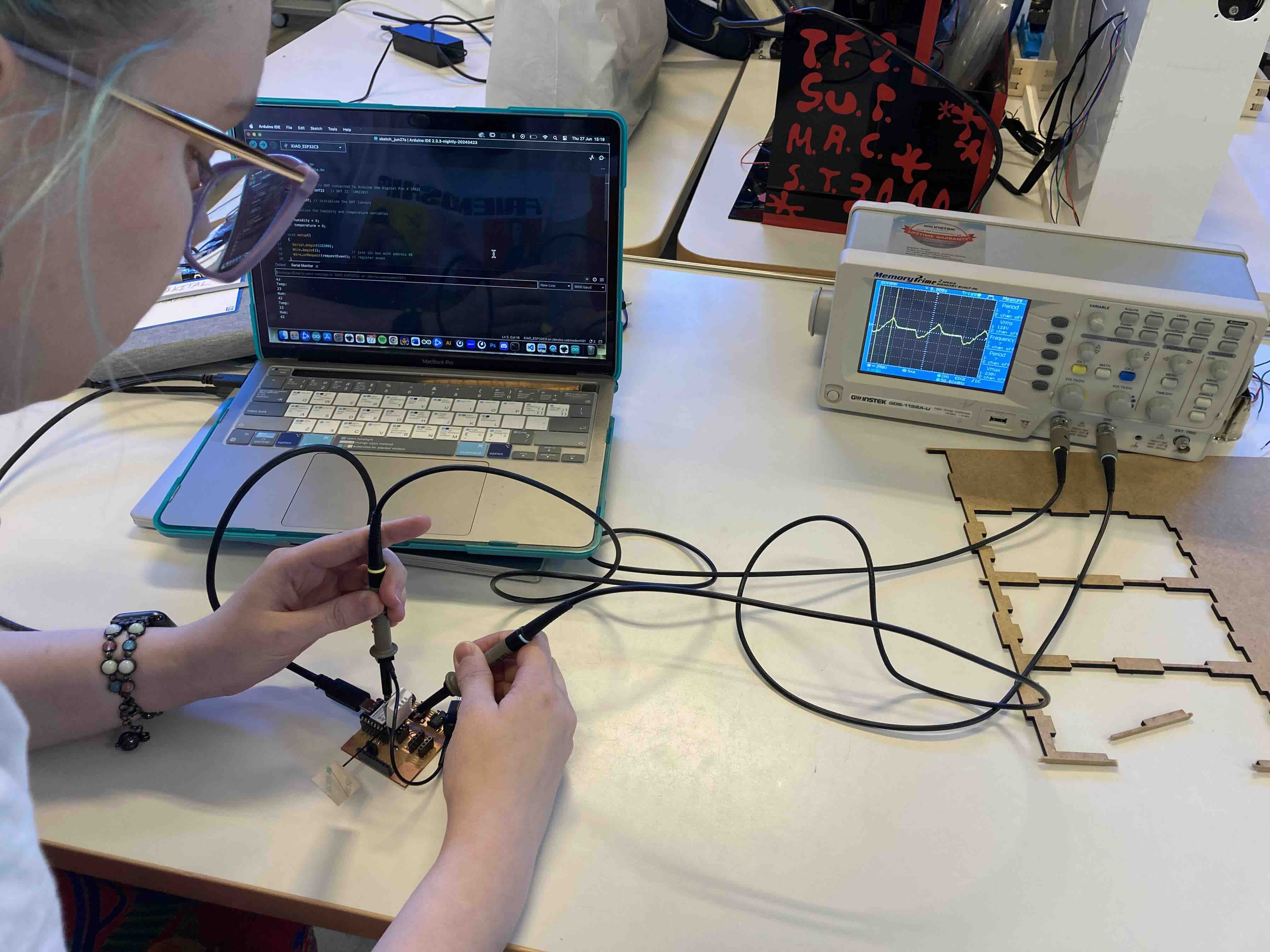
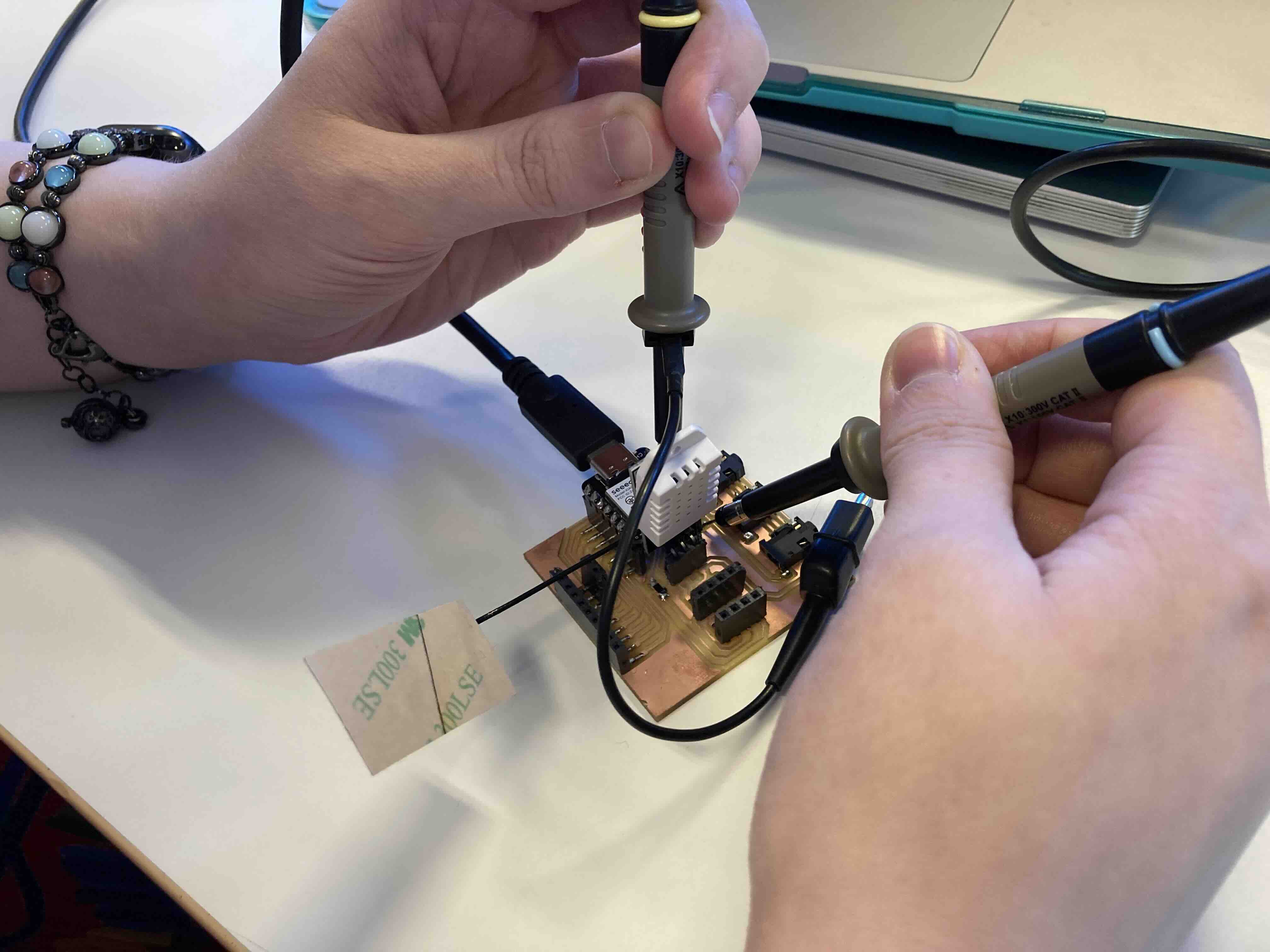
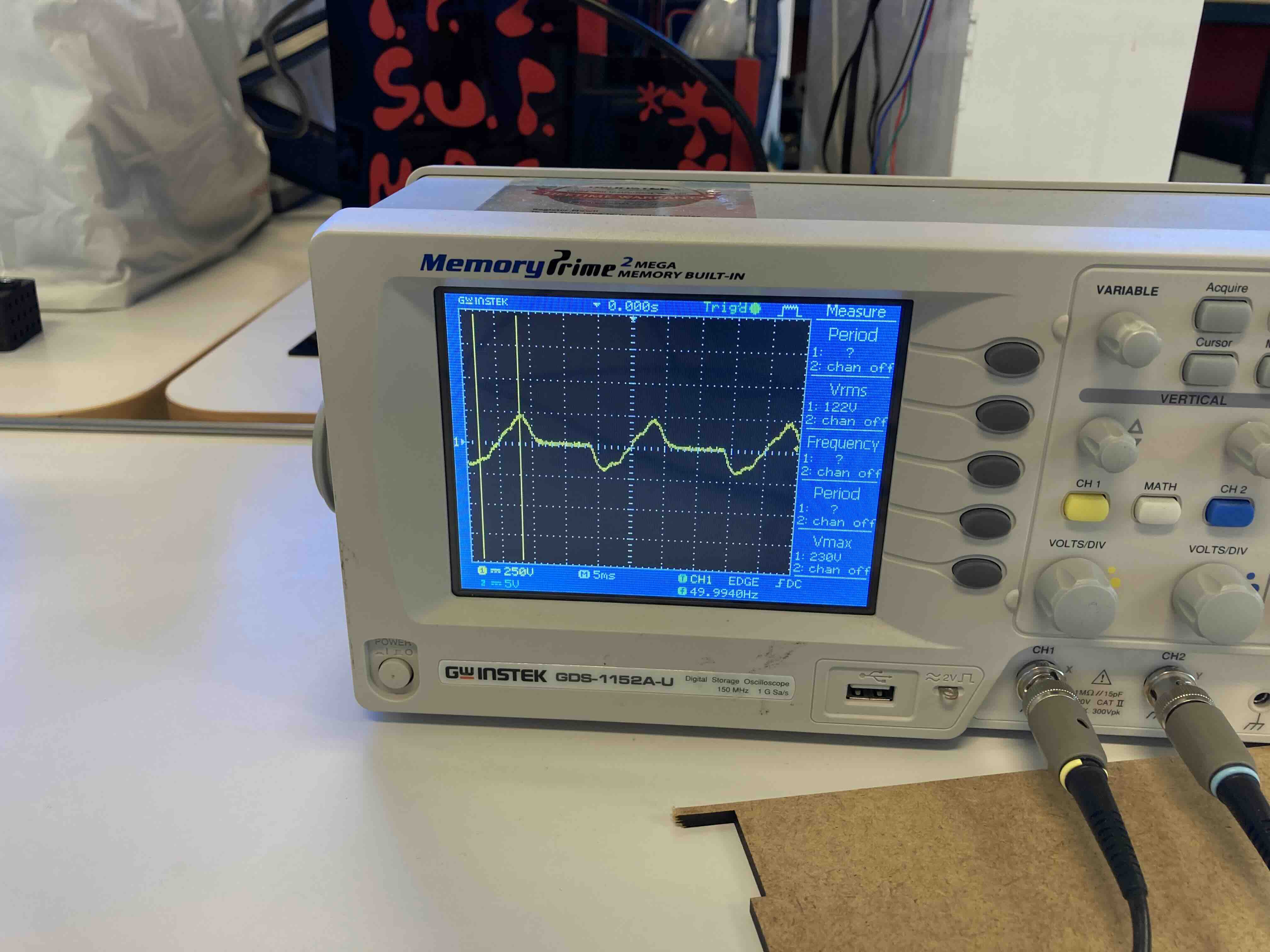
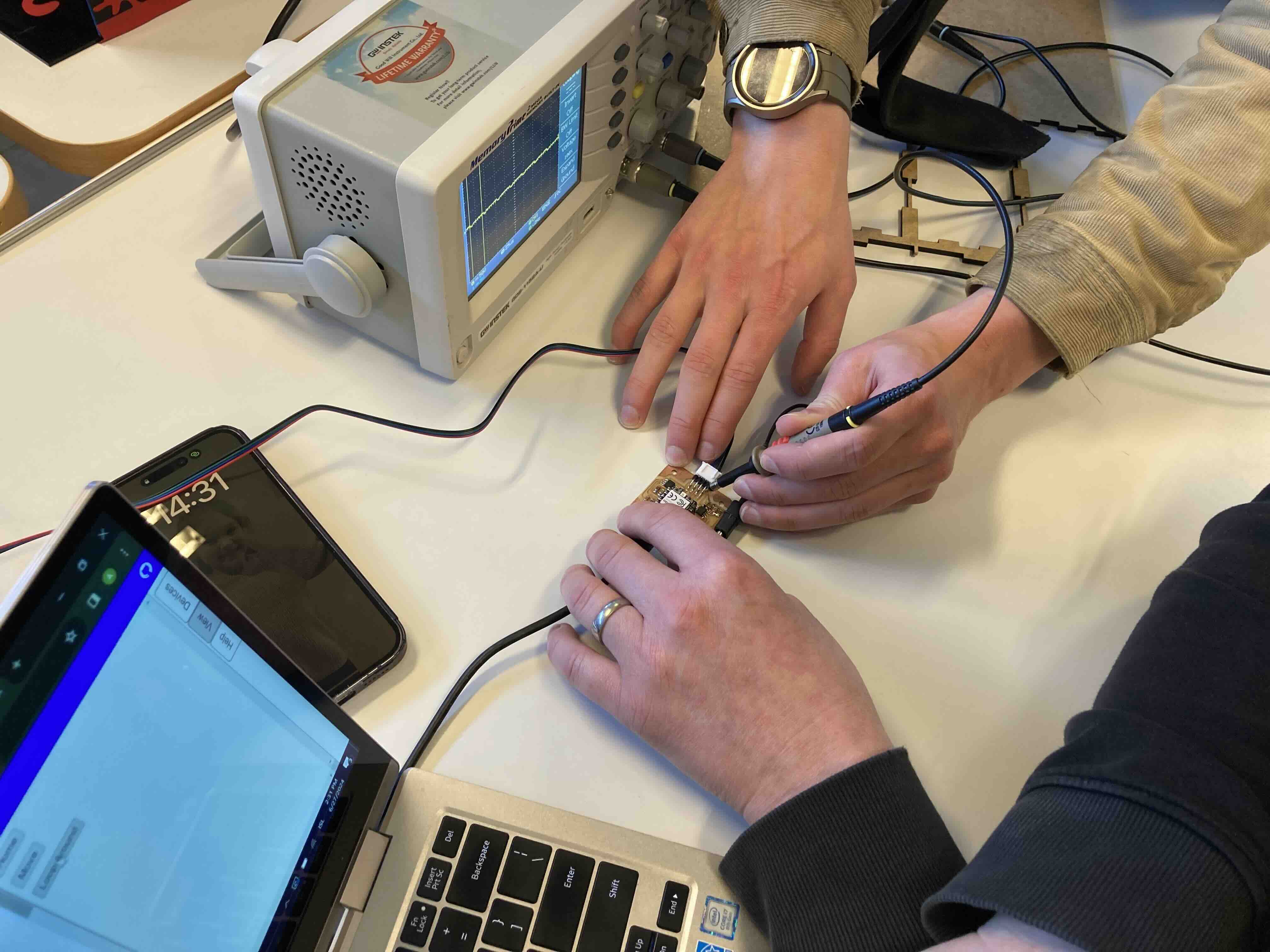
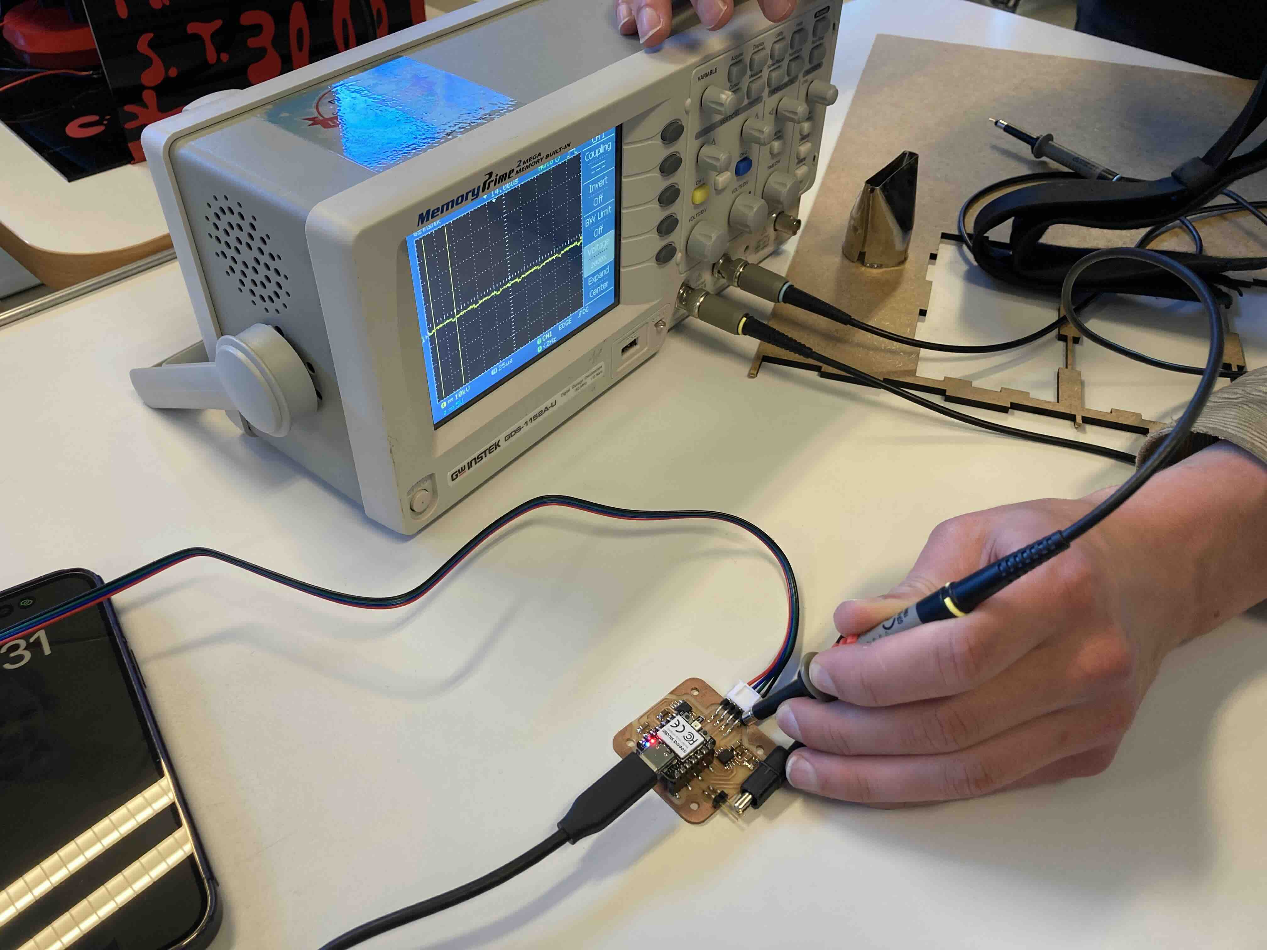
The board is from Andri-semundsson (instructor).. The board is DHT22 (humidity and temperature sensor input) using the oscilloscope to measure digital signals from board, humitdity and temperature. The oscilloscope shows how electrical signals change over time by graphing them as waves on a screen. It displays these signals as waveforms on a screen, allowing you to visualize the amplitude (strength) and the frequency (rate of change) of the signal over time. This helps in analyzing and troubleshooting electronic circuits and systems.Square waves are typically generated by electronic devices called oscillators. These devices produce a waveform that rapidly switches between two voltage levels: a high level (often represented by a positive voltage) and a low level (often represented by zero or a negative voltage). The transition from high to low and vice versa is almost instantaneous, resulting in the square shape. Square waves are commonly used in digital systems and electronics because they have well-defined transitions between high and low levels, making them suitable for representing binary data (0s and 1s) in digital circuits. They are also useful for testing and evaluating electronic components and systems, as their distinct shape makes it easier to detect and measure certain characteristics of the signal, such as rise time and fall time.
dht22 sensor

	**
#include
#include

#define DHTPIN 4  // DHT connected to Arduino Uno Digital Pin 4 (PA3)
#define DHTTYPE DHT22   // DHT 22  (AM2302)

DHTStable DHT; // initialize the DHT library

// Initialize the humidity and temperature variables

int humidity = 0;
int temperature = 0;

void setup()
{
  Serial.begin(115200);
}

/* The Main Loop */
void loop()
{
  int chk = DHT.read22(DHTPIN); // Read DHT22 data.

  temperature  = DHT.getTemperature();

  // Read humidity
  humidity = DHT.getHumidity();
  Serial.println("Temp: ");
  Serial.println(temperature);
  Serial.println("Hum: ");
  Serial.println(humidity);

  delay(2000); /* Add 2 second delay in the loop */
}
**

*
*
*
I used a simple XIAO-ESP32-C3 board that I had made in week 8. I used that board to measure the lED Lights. I used it to see the code and energy consumtion of the LED. On this board I was measuring the digital signal to the RGBW LED strip. I then tested the hotdog condiments dispencer (week 10) board to see the output pin for the stepper. There I was measuring varying anlog signals from the board. The third board we measured was from my instructor DHT22 (humitity and tempature sensor) board. On that one we measured the digital signal from the board. Measuring humitity and tempature. This week was relative straight forward. Reminded me of project I had done in electronics. I will used the knowledge I got from the engery consumption on my wings. The main thougth being how big a battery pack I will need to run both the lights and servos for 6 plus hours.