Week3. Computer controled cutting
Group assignements
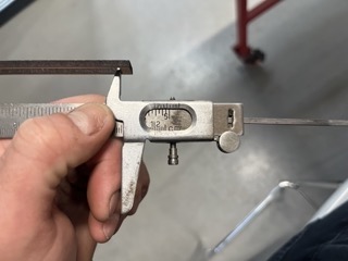
To start off the week, we had some group work to do and now I'm going to tell you how I calculated the kerf and how I played the game. The kerf is the amount of matter destroyed by the laser. It therefore corresponds to the radius at which the laser passed. To determine this value, we had to think about how we could do it. We decided to make as many passes as possible along a certain length and then determine the difference, as this would allow us to repeat the laser pass a large number of times and thus achieve greater precision. The measuring tool we used was a calliper, which is a precision measuring tool. The caliper we used had a maximum length of 12.5cm, so we took care not to exceed 12cm by making a design on fusion 360, with 23 rectangles 5mm wide included in a frame 13cm long.
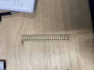
We made an initial cut which didn't work because the different pieces weren't cut enough to be separated. Even if we'd broken them, measuring them wouldn't have been useful because the edges wouldn't have been glued, so the measurements would have been off. Alexis later realised that we were having this problem because the minimum power setting on the cutter was too low, so we were getting a poor cut when it slowed down at the end of the pass. I still managed to make a good cut by reducing the speed to 20% with 90% power.
You can find the dxf file here
Analysis of results
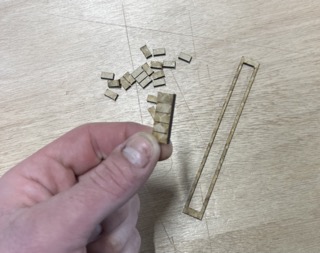
Once my cutting was complete, I was able to take the measurements for my test. I obtained a measurement of 114.1mm by putting my sections end to end, making sure that they were aligned on each side and that the squares were flat in order to get the most reliable measurement possible. On the frame side, there was a length of 120.2mm that was cut out. So over a distance of 12cm there was a difference of 6.1mm, which corresponded to all the kerfs added together. By dividing, the total difference of 6.1mm for the 24 laser passes that separated them gave us the result of 0.25mm in diameter. This value seems consistent and when Alexis subsequently carried out tests of different bonds, he only subtracted the kerf from the thickness of the material and we had a pretty firm joint.
Joint clearence
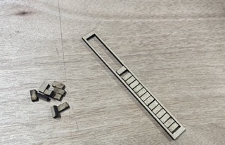
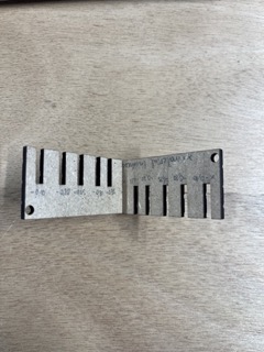
We then turned our attention to joint clearance. This is the clearance between the materials. If the assembly is to fit together correctly, we need to find the right gap so that the materials fit together properly. We therefore modelled a strip on fusion 360 with different slots of different widths to determine the best fit. The material used for these tests was 3mm thick MDF. We created a parameter for the thickness if we wanted to try with another material as well as a tolerance which is the step difference used between the different cut-outs. So in order we had slots of 2.9mm, 2.8mm, 2.75mm, 2.65mm and 2.60mm.
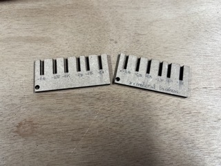
It's important to note that the kerf hasn't been removed, so the third slot corresponds to the junction with only the kerf missing. There is still a lot of play. The press-fit is good at 0.4mm, i.e. 0.15mm more than my kerf. In order to estimate where the limit is, I cut another assembly with even lower values to determine the limit for fitting together.
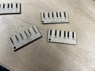
To our great surprise, we didn't find a limit, even if we went to 0.55mm less than the diameter of my MDF, we still managed to fit them together, even if it required a lot of force. The feeling is that at around 0.15mm less than my kerf, the assembly is sufficiently rigid.
You can find the dxf file here
You can find all of our group assignments on the Agrilab page of the week
Individual assignment
During the week, we were given individual assignments:
-cut something out on the vinyl cutter
- design, laser cut and document a parametric construction kit,
- taking into account the saw line of the laser cutter,
- which can be assembled in a number of ways,
- and for extra credit, include elements that are not flat.
We started the week on Thursday, after our lessons with Neil, with introductory workshops on the different methods, namely the laser cutter and the vinyl cutter. We were then able to work on the different machines by doing our group and individual projects.
Laser cutting
To get started with laser cutting, we first learned how the machine works, how it can be used and, above all, the safety that goes with it, given that it's a fairly dangerous tool.
The machine
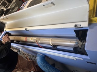
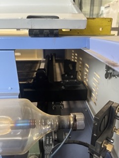
The laser cutter we have at Agrilab is a CO2 laser cutter from MLlaser, a ML-W1290 150W to be precise. It has a 1200 x 900 mm cutting table. This machine has a water cooling circuit to cool the CO2 tube in which the laser is created, and is fitted with a ventilation system that exhausts the air outside to avoid breathing toxic compounds once burnt.
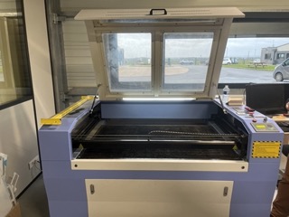
The machine works on the principle that in a long glass tube at the back of the machine. Photons are sent out at high speed and collide with the CO2, which multiplies them and causes a chain reaction. At the end of the tube is a mirror. There are a total of three mirrors on the machine, and it is thanks to them that the laser is directed to the cut element.
This machine works using lasercut software and only lasercut software, which isn't very practical because lasercut only accepts files in dxf format and is fairly old. For more information about the machine, please visit the dedicated page on the Agrilab wiki.
Project
During this week, I wanted to make a replica of a wooden internal combustion engine using the laser cutter. But one of the instructions for the week was to make an object that could be assembled in different ways, so I chose to make two projects. The first was quite simple, made up of multiple elements in the shape of a pentagon or a small circle that could be assembled in a number of different ways. The second took a lot more time and is therefore my motor.
The first project
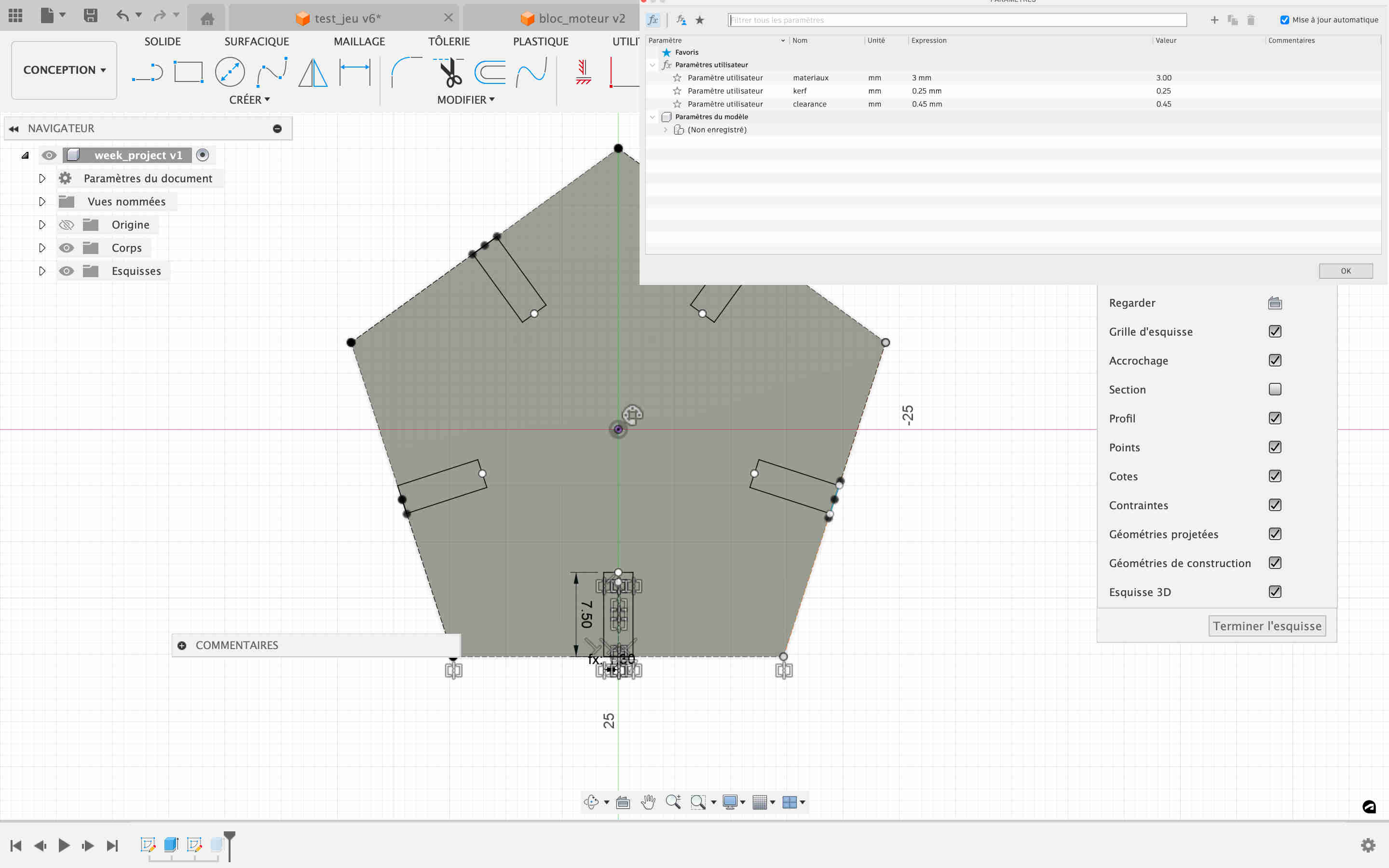
I'm presenting this project first because it's the one that's already finished and because it answers more of the questions asked. This second design to start with is parametric unlike the other, so I can adjust different variables and it can be assembled in multiple ways.
To start with I created my design on 360 fusion, creating 5 points by making a circular network, I then connected them to form my pentagon. I then extruded my sketch with the thickness of my material, which is parametric, and designed the notch. To do this I simply indicated that it should be the size of my material minus my kerf and clearance, with a depth corresponding to half the small circles. I then made a network to put it on each side and my part was ready. As for the circles, I simply made a 15mm circle and the thickness of my material, always taking into account the kerf and clearance.
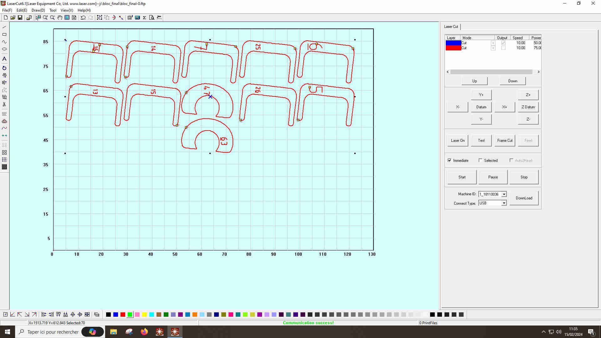
From Fusion 360 to laser cutting
Once my fusion file was finished, I had to export it to the machine. First I exported directly from fusion 360 to dxf. I was encountering problems for various reasons, in particular the construction lines, and I was advised to use an add-in that had been shared on Mattermost to avoid these problems. It has been developed by shepper utilities and can be downloaded simply by following this link. However, it only exports in svg format, so I had to go to inkscape to change the format. All I had to do was open it, go to files> save as and select the correct format (dxf) and save. With a USB key I could then put it on laser cutter, the cutting machine software. To do this I had to open the software, go to files, then import and select the dxf file to be cut. When I opened it, I sometimes had a change of scale of around 10 on certain components, so you need to check that the size corresponds to that of the design.
Cutting settings
To get the best results from our cutter, we need to adjust a number of parameters. To begin with, it's important to adjust the focal length of our cutting machine, which is equipped with an automatic adjustment system. All you have to do is place the materials you are going to cut on the machine's work surface, place a specific metal plate on top of the material and place the magnetic sensor of the cutting head underneath it, choose the Z axis and press the datum button. The head will move down until it picks up the metal and then move up again. We can then proceed to set the speed and power; we've determined these values for the different materials we use in our group assignments. In my case, I set the speed to 75 and the power to 100. You can then start cutting.
Here's the result I got when I cut it out. I started my first test again because I'd made a mistake in calculating the clearance I wanted and so I had too much clearance to get a good press fit.
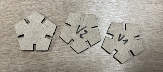
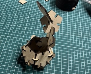
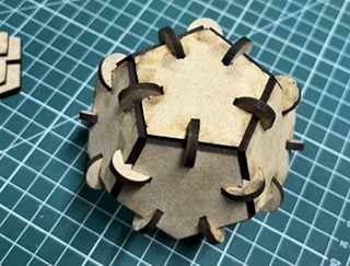
Once this error had been corrected, I was able to cut all the parts I wanted. The assembly can be put together in many different ways, depending on how you put it together. Given that the shape I've made is a pentagon, if you assemble the different parts by making them all touch each other, you get a certain ball shape.
You can find the dxf files for the pentagon and circles here
The motor project
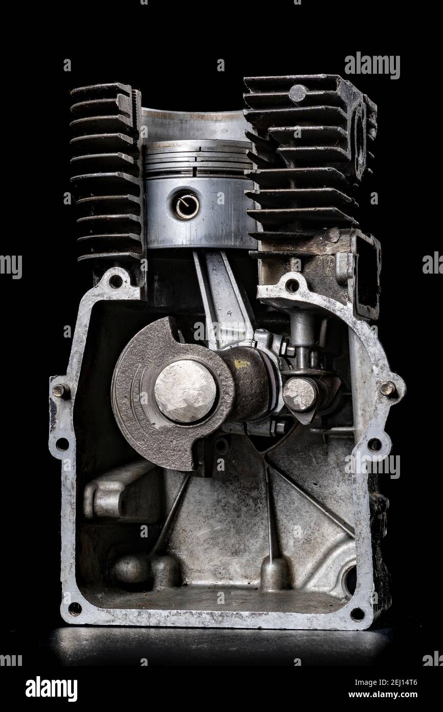
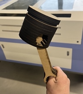
To design my engine I first thought about the different ways it could work and the shape it would have. I was inspired by this image, because the engine is completely vertical, so it's quite simple to make one that stands up without too much difficulty. The aim was to make the rendering as realistic as possible and that's why I chose to work by stacking multiple layers. I also wanted to be able to animate it manually so that I could see the movement of the different organs that make it up. I started by creating the pieces one by one, defining the measurements by feel. In order, I created the piston, connecting rod, crankshaft and finally the engine block. All these designs were done on fusion 360. As I created the measurements myself, it took me a long time to adapt the different parts to make sure they didn't collide with each other, especially as I had to make sure I had multiples of 5.9mm, which is the thickness of the MDF I use. Some parts are uniform and therefore very simple to develop, while others require more work.
I havent finished to dévelop the last part, the motor block but we can see below what it should look like:
Crankshaft and connecting rod
These two elements are quite simple to create, as they have the same contours on the same plane, so I simply had to create my object and put it in the right format. As all the layers are similar, I simply had to cut each one the number of times necessary to obtain the desired thickness.
Piston and engine block
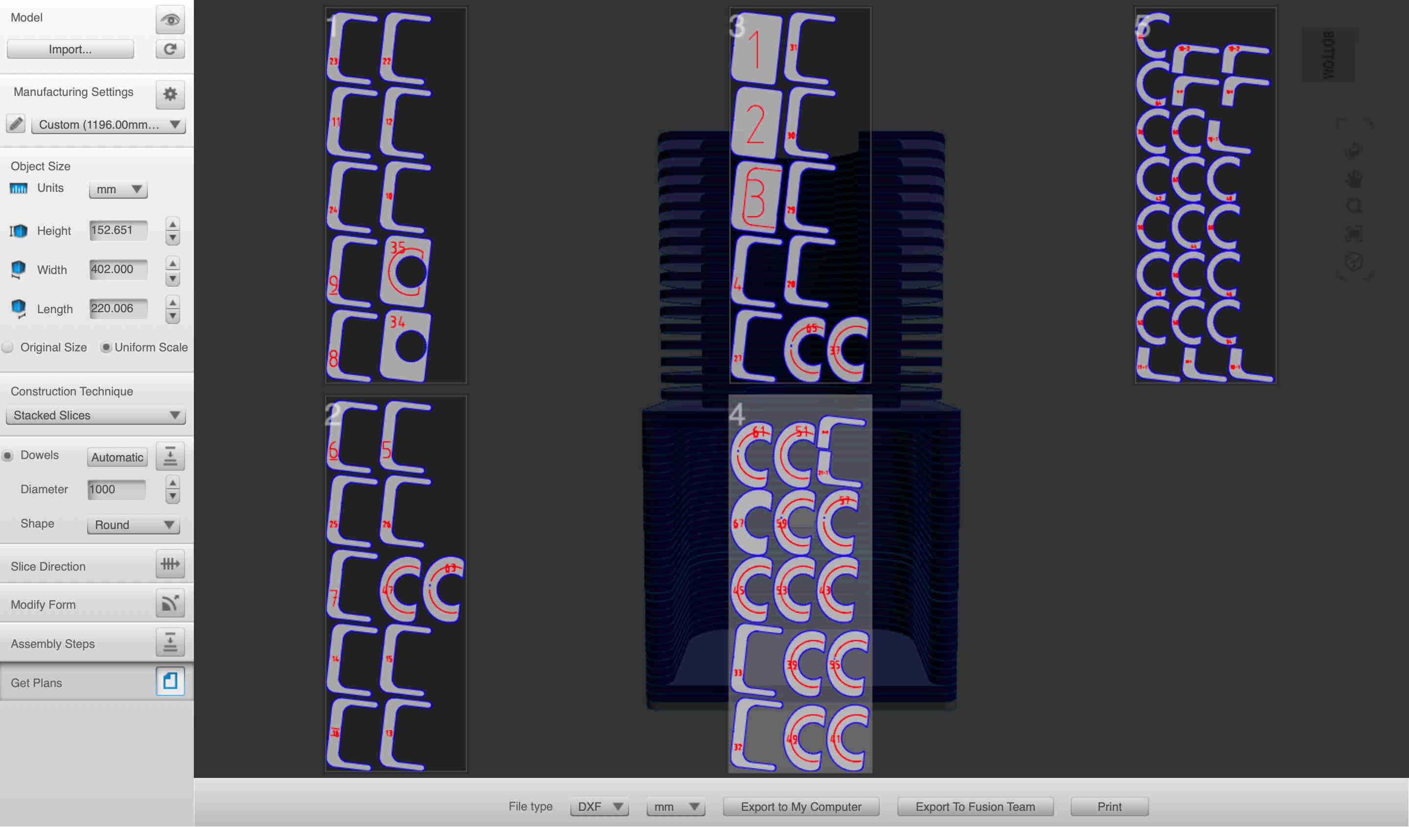
For these two parts, the work was much more extensive because they didn't have the same height measurements, so I had to use a different method. To do this, I modelled my parts like the others and then used the 360 fusion slicer. This can be downloaded from the Autodesk website but is no longer maintained, so there are some annoying bugs that make it difficult to use. Once downloaded, all we have to do is save our fusion 360 design in stl format and open it with it. Once you're in the slicer, you need to make a few settings, starting with scaling. By default, it opens the document in "in", so we need to change it back to mm and set a value to get the measurements right. You can then change the size of the material, something I completely forgot to do at the start, so I had one document per part, which was very time-consuming.
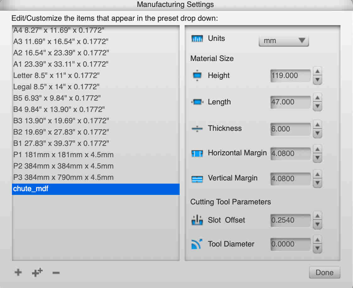
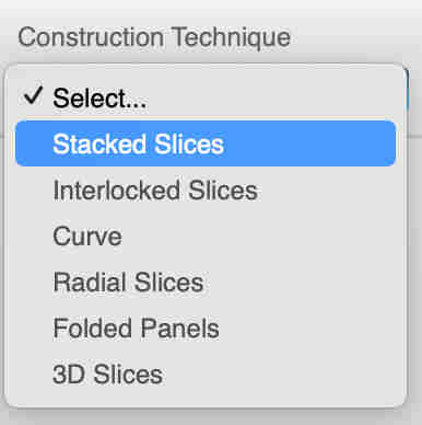
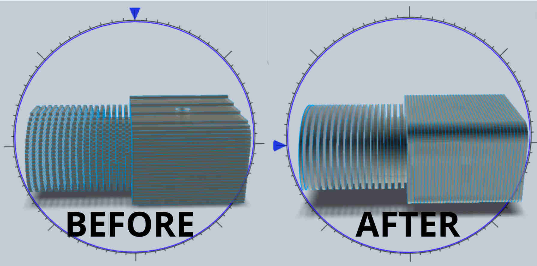
The slicer made a border to break up the sheet of materials, so I had to go back to inkscape to remove each component and then put it on deepnest, but I also had to change the format because deepnest couldn't open my dxf files. In the end I didn't manage to send my deepnest design to the lasercut software and lost a lot of time doing so. I then realised my mistake and by entering the correct material values, you can enter the size of your material and its thickness. You can choose the type of technical construction, in my case stacked slices. You can also choose whether to use dots to link the materials together, I didn't want to bother with that so I set the number very high so that they would disappear from the drawing. You can then choose the slice direction, in my case I rotated it by 90° so that the slices are in the direction of the motor blades.
Then all you have to do is go to get plans and select the export format, the unit of measurement and export it wherever you want. In my case, I need 5 sheets of mdf to make the block.
I used the same method for the piston. I'm thinking of trying the deepnest again if I have time because the sheets the fusion slicer gives me aren't full enough for my taste and it can be very time-consuming to rearrange them manually. I'd already used a sheet of mdf to make the piston, crankshaft and connecting rod, so I'll need a total of 6 if I make the engine block. For the moment, I still have to make the engine block, but the rest is cut out. To assemble the piston, I used wood glue that I applied between each of my layers, then clamped them together for about 2 hours while the glue dried.
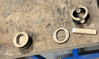
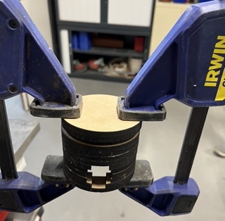
I made the mistake of not using anything to guide the different parts of my engine, so I've got a slight gap developing between the different pieces of my cylinder and it's not perfectly aligned. I should have made sure to add pins to guide each piece
You can get here, the dxf of the connecting rod, piston(1, 2, 3), crankshaft and engine block files (1, 2, 3, 4, 5)
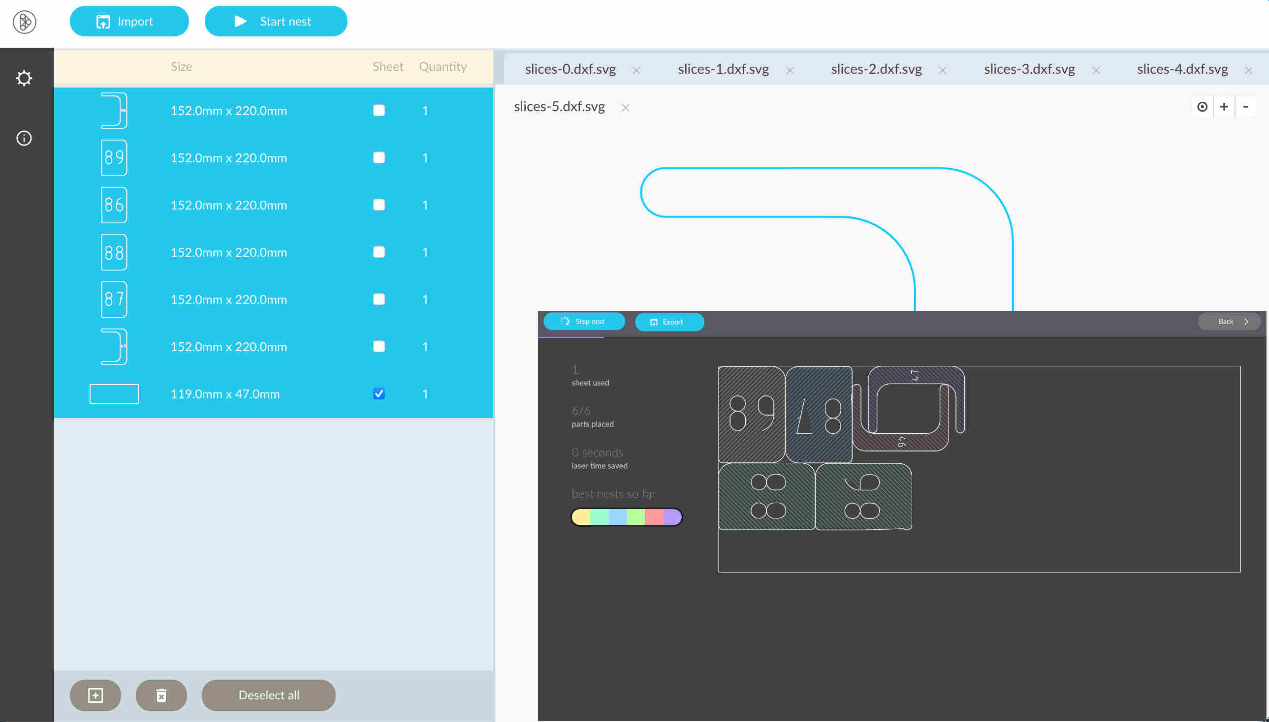
Deepnest
The software is quite simple, just import the document you want to reassemble and specify the size of your material. Once you've selected everything, press start Nest and the software will try to find the best possible assemblies. However, the documents I imported in dxf were not displayed and I had to import the svg and then export it in dxf, which took a long time.
Vinyl cutting
During the introductory session, we had the opportunity to try engraving a model if we wanted to. So I chose to engrave the raven design I'd created during week 2.
I didn't make any documentation during this process though, so I cut out another design to explain the steps one by one.
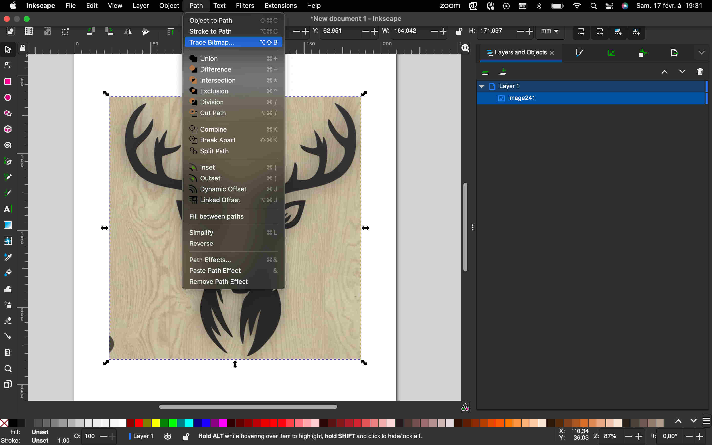
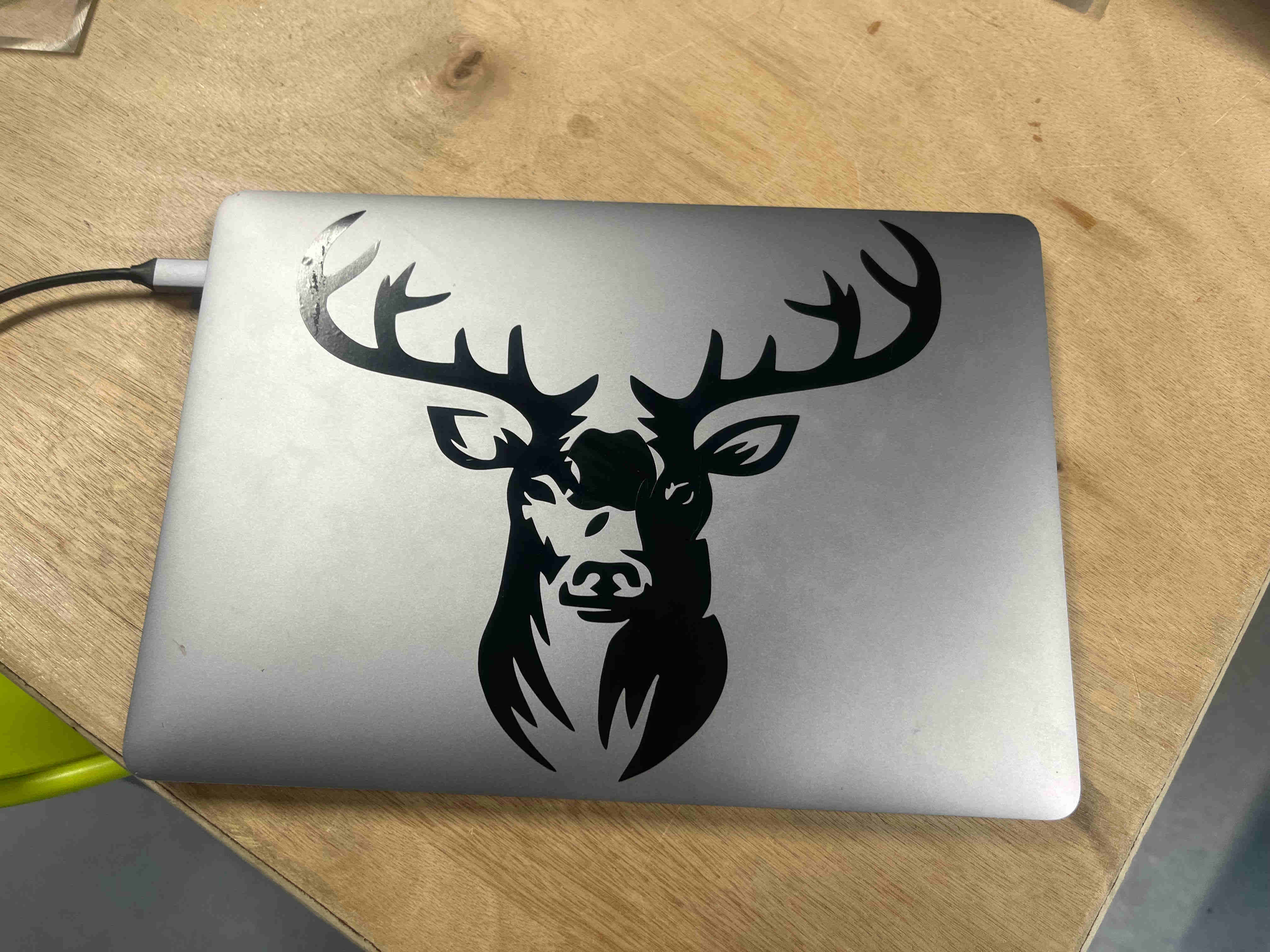
In order to make a second design I wanted to make a decoration sticker to put on my computer, I didn't want to design a new one so I chose to take one from the internet. I chose this image of a deer. Once I'd downloaded it, I imported it into inkscape, then I just had to select the image and go to path then trace to bitmap in order to vectorise my image..
Once I'd vectorised my image, I retouched the details that didn't fit to give it the shape I wanted. I then saved the file as an svg and reopened it with the computer connected to the vinyl cutter.
You can find the svg file here
The vinyl cutter
At Agrilab we have two vinyl cutters, a Silhouette CAMEO 3 and a Rolland CAMM-1 GS-24. In my case I chose to use the Rolland for a number of reasons, firstly because I had already cut the corbel with it, and also because it is wider, which means it can be used more often. For more information about the machine, please visit the Agrilab wiki.
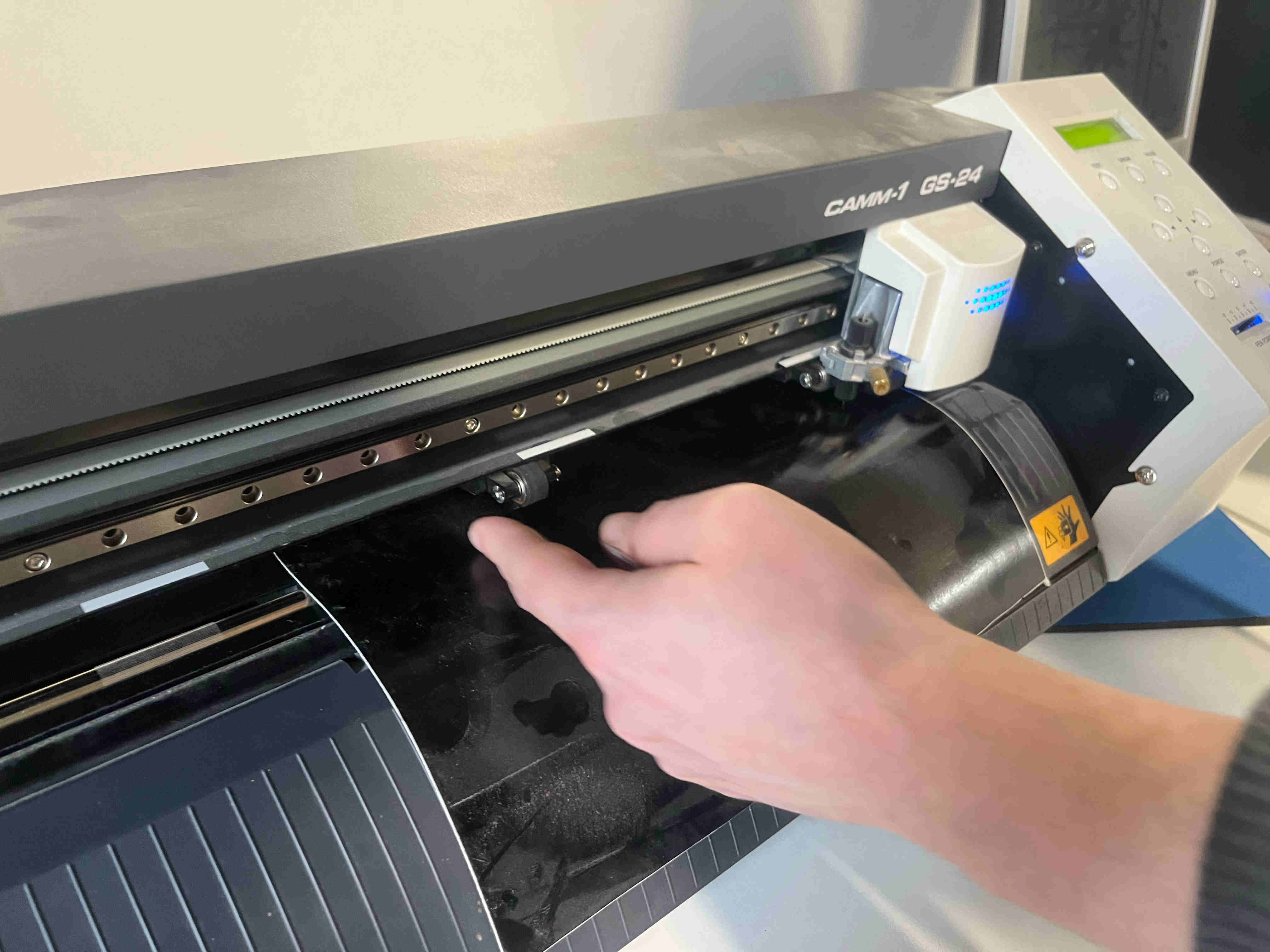
First I had to insert the media, to make my logo, I chose to use black media. Loading it is quite simple, just put the roll on the back and pass it through, coloured side towards us. You need to make sure you keep the skids holding the media to insert it, and lower the handle once the skids are down. Once you've done this, you can fix the origin by placing the blade where you want it and pressing the origin button for a long time.
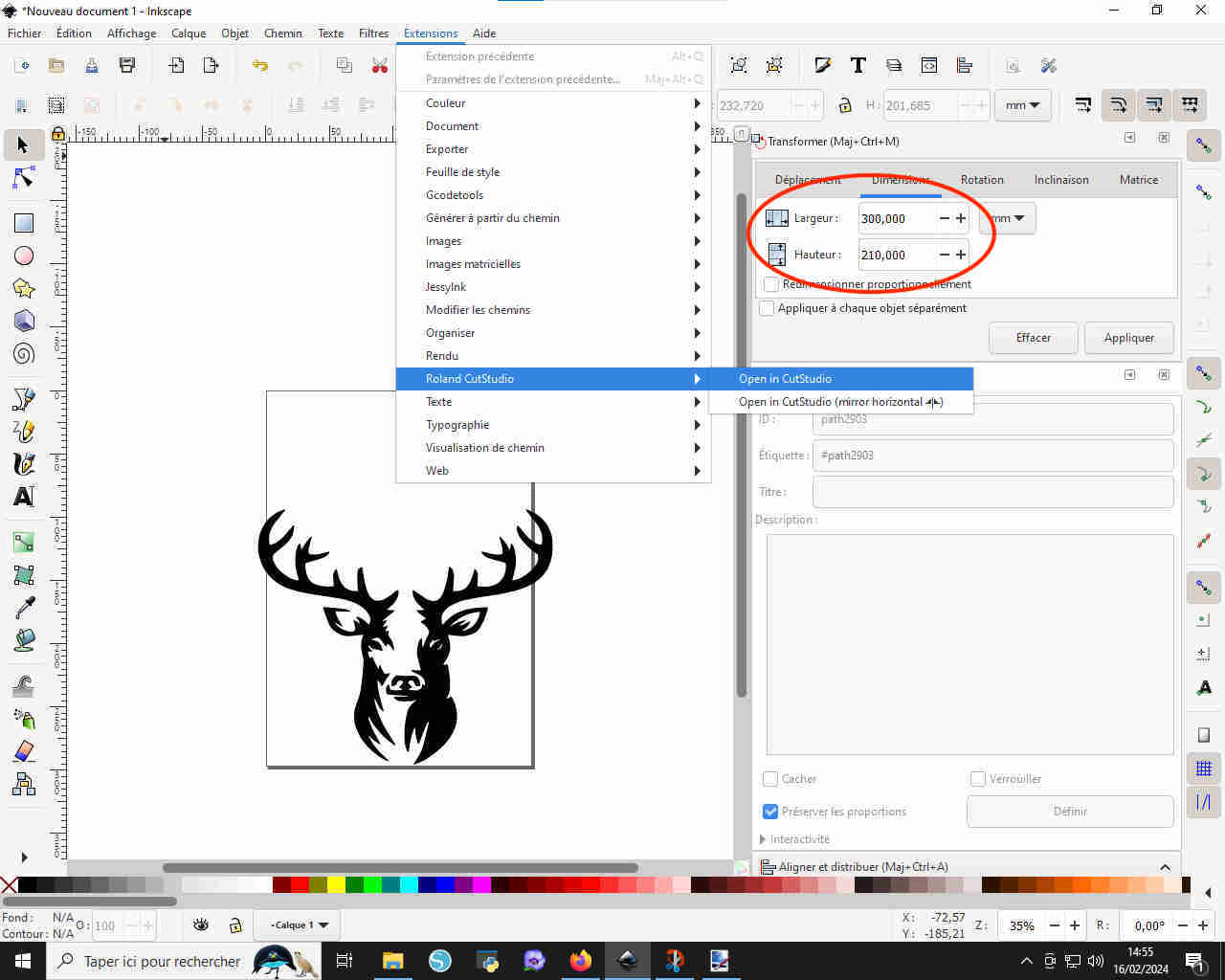
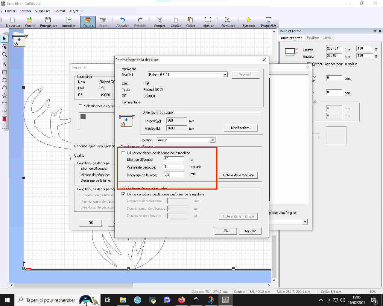
Once the machine is ready, all you have to do is open the inkscape file, go to extensions, select Roland CutStudio and then open in cut studio. I also resized the design to fit the dimensions of my computer, i.e. 300 by 210mm.
First of all, I made an initial cut using the default settings, i.e. a speed of 15cm/s and a blade offset of 0.5mm. The result was catastrophic and tore the vinyl.
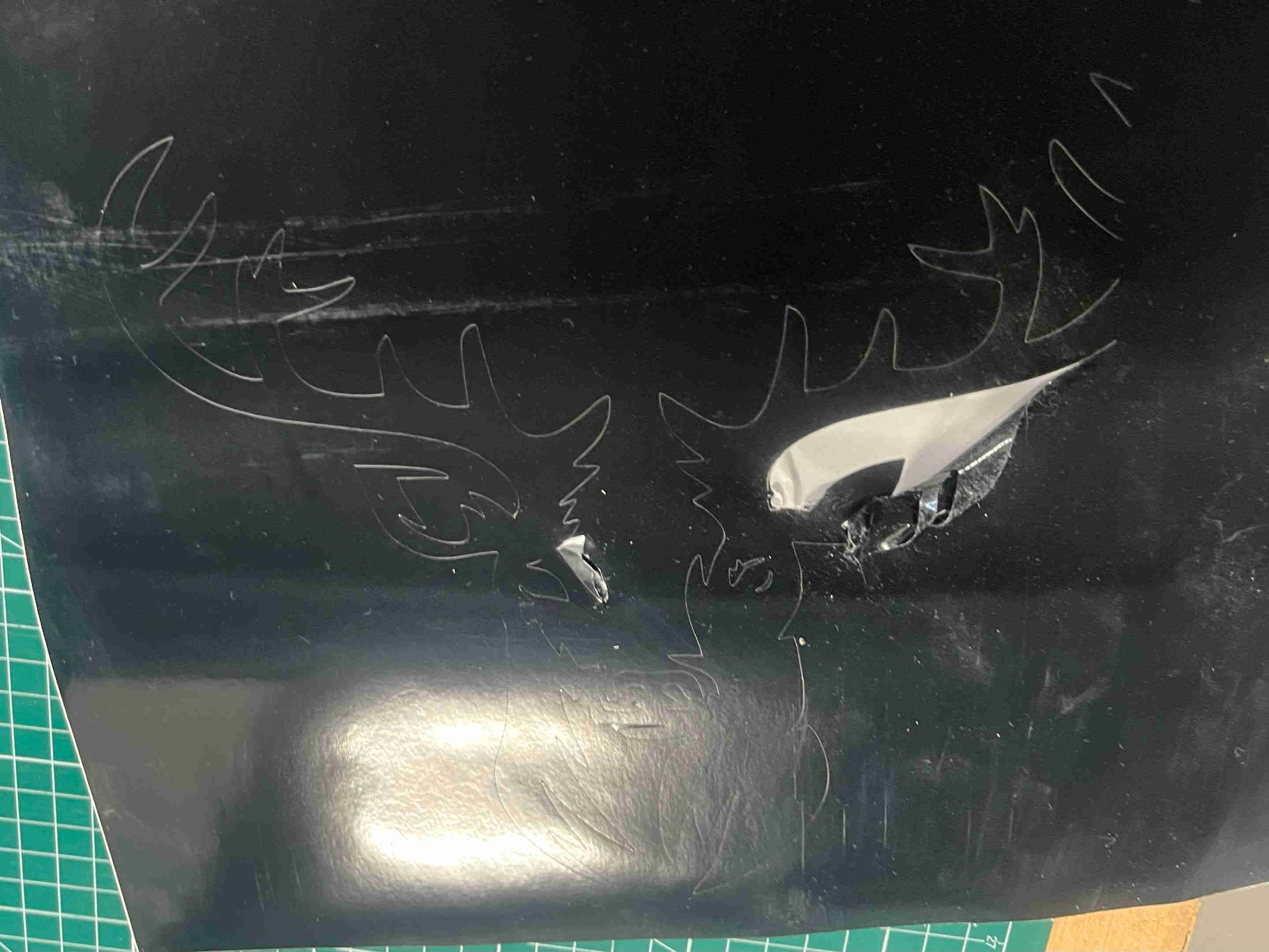
I repeated the experiment by lowering the cutting speed to 7cm/s and shifting the blade by O.2mm and the result was much better. I could have shifted the blade a little less because I was having trouble separating the different pieces of media, but I still managed.
Once the unwanted media has been removed, you can stick some transfer media onto your cut-out to put it on another surface. Simply place it gently on the surface and remove it, making sure you catch all the pieces.
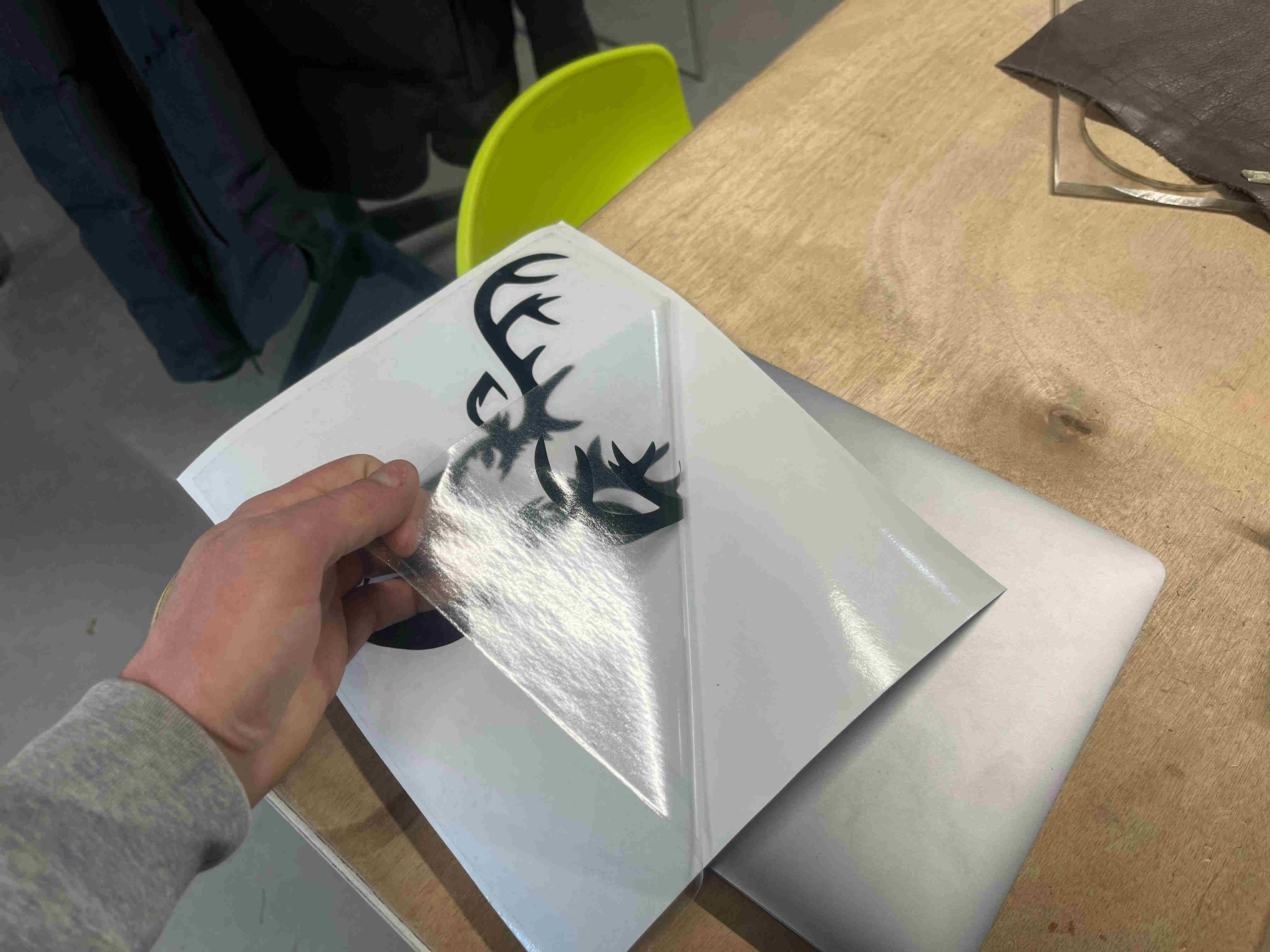
Once you've stuck the sticker onto the transfer media, you can apply it to the object you want to stick it onto. After going through the various stages with varying degrees of success, I managed to miss the last one by sticking my sticker onto my computer...
Files
Test kerf Test clearance Pentagone Circle crankshaft Connecting rod Piston 1 Piston 2 Piston 3 Engine block 1 Engine block 2 Engine block 3 Engine block 4 Engine block 5 Deer