During week 7, we focused on the operation and use of CNC cutting machines. Our assignments were as follows
group assignment
do your lab's safety training
test runout, alignment, fixturing, speeds, feeds, materials,
and toolpaths for your machine
individual assignment
make (design+mill+assemble) something big (~meter-scale)
extra credit: don't use fasteners or glue
extra credit: include curved surfaces
To kick off the week, we had two different workshops on Thursday, the first focusing on creating a design and preparing it for CNC on 360 fusion, while the second was more focused on using the CNC milling machine. During the first workshop, we learned how to model a stool and prepare the gcode, then during the second workshop, we cut out a small piece of wood made up of pockets and contour cut-outs in order to see the different machining techniques.
Group assignments
In order to make our group assignments, I wanted to try and characterise different materials. To do this, I created a parametric fusion test that I used on the following materials
| material | thickness |
|---|---|
| MDF | 18mm |
| OSB | 18mm |
I started by machining OSB and MDF with a 6mm cutter and the respective parameters for each material. I tried to reproduce the test file that our instructor showed us containing the cut is close, I made it parametric so that I could change the thickness of the material used. You can find it here. The CNC run was a real failure because I probably hadn't prepared my files properly. With the mdf, the pocket didn't cut, and with the OSB it was the tabs that didn't fit. However, I was pleasantly surprised by the pocket in the OSB because the finish is rather smooth and flat for such a coarse material.
You can find all of our group assignments on the Agrilab page of the week
Individual assignments
Badge
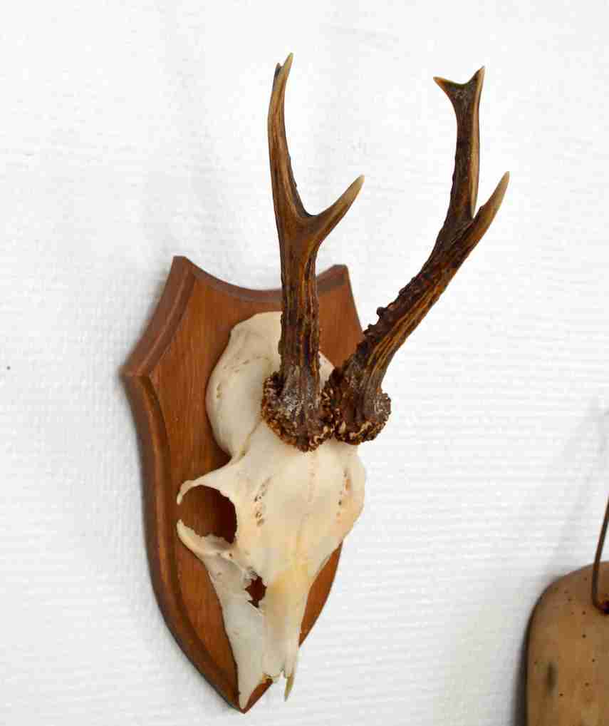
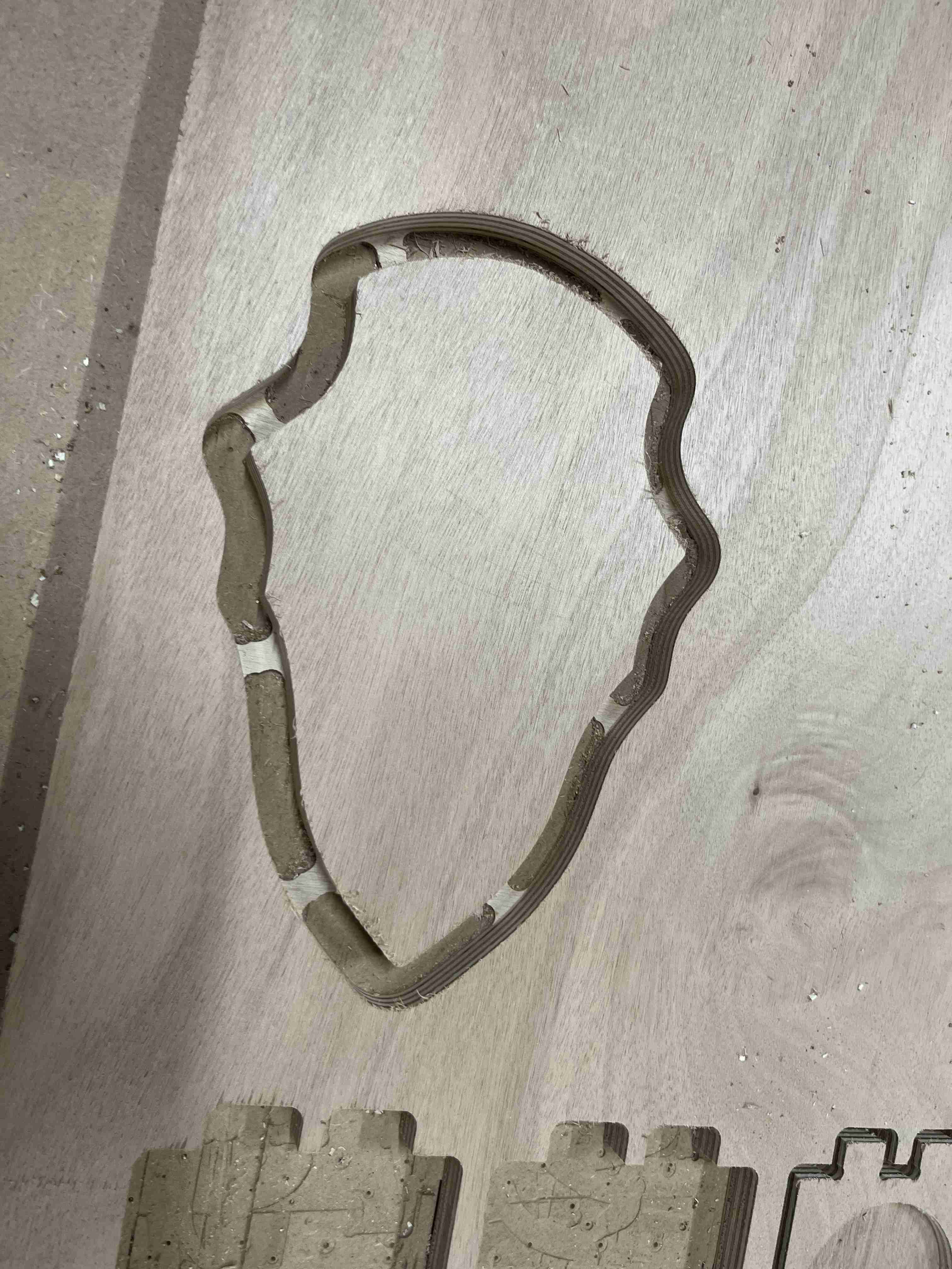
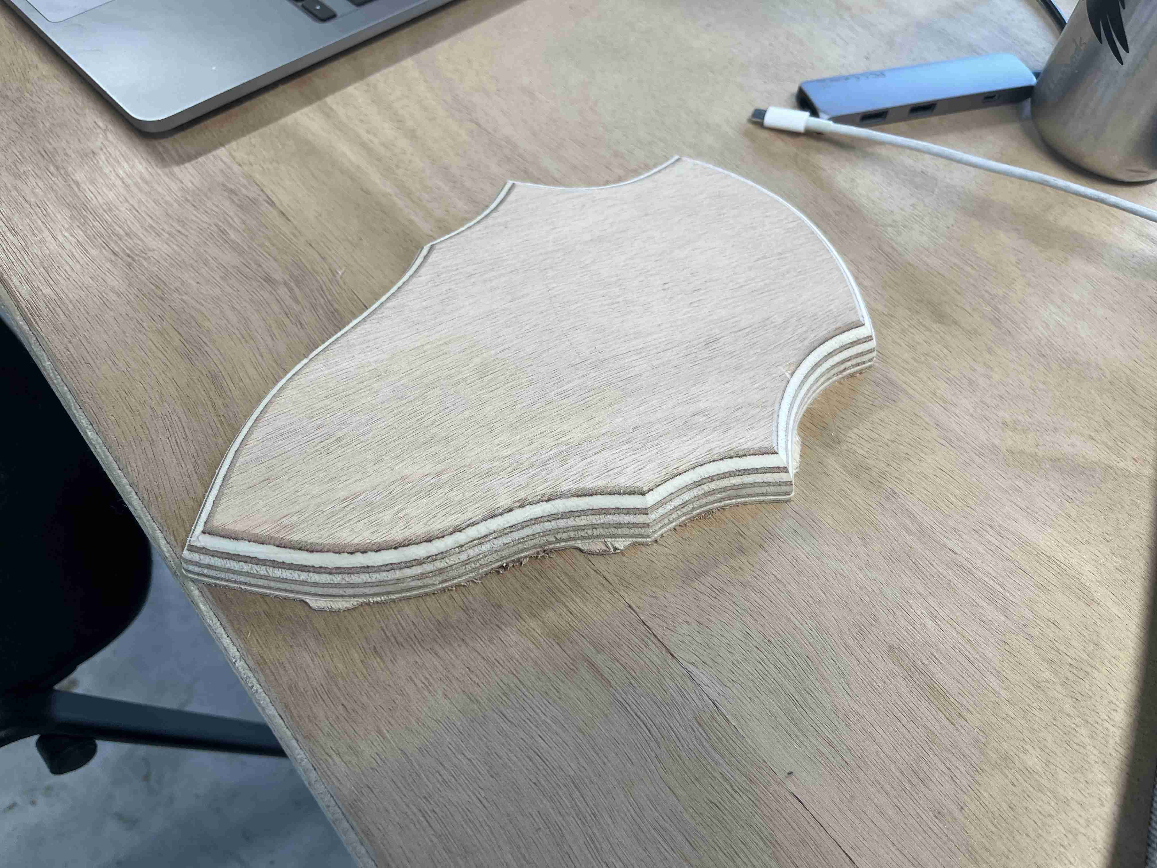
To get the hang of using the software and the machine, I wanted to make a small object that was quick to make and easy to model. To do this, I chose to make a deer patch. In taxidermy, an escutcheon is a wooden plate used to hold a trophy (the animal's skull with its antlers). To illustrate my point, you can find an example on the internet:
To do this, I started by taking a photo of an existing design on a internet reseller which I then processed in Inkscape to create the outline of my object in svg format. So that I could then use it on fusion 360.
Once I was on the fusion 360 software, all I had to do was go to the design menu and select the insert function, then insert an SVG file and select my design. Once it's scaled to the size you want, you can extrude it to the size of your material and then go to the manufacturing menu to prepare our design for cutting.
Once you are in the manufacturing menu, you need to start by creating a fixture. To do this, go to the fixture menu and select new fixture. A yellow shape is then created, representing the raw material you want to use. We can start by setting our X, Y and Z axis origins. As our origin is on the same board as the material to be cut, we need to make sure that the Z is on top of the fixture. You can then choose the different values you want to use in the fixture parameters before confirming. In my case, I considered my blank to be a block of relative size and I added a lateral offset of 20mm in order to have enough space for our different cutters, especially the second one I'd use which is very wide because it's a radius cutter.
The mills
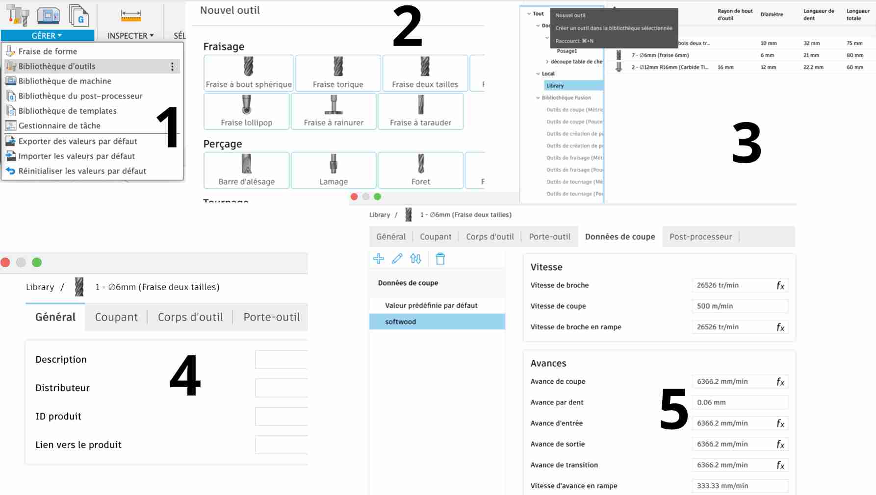
Once you have prepared your fixture, you can prepare the cutters. To do this, go to Manage, then Tool Library. A new window will open and you can choose library, then click on the symbol +at the top to add a new tool
You then come to a menu where you select the type of cutter you want, in my case a two-size cutter.
ou can then indicate the name you want to give it and the distributor. You can then go to the Sharp and enter various data, the number of teeth, the materials, the lengths, all this data is given by the manufacturer on the tool box or on their website. Next, we have to enter the cutting data. To do this, we used two different methods, including Alexis, who tested the same cut with the same cutter but using two different methods.
Constructor website
The main milling cutters we use at Agrilab come from the manufacturer Sorotec. To find out the parameters of our milling cutter, look up its reference on the manufacturer's website and open its datasheet. here. If you don't speak German, you'll need a translator, as the data is in English. Once on the datasheet, you have access to two main values. The cutting speed in m/min, which depends on the material being worked on, which in our case is softwood, so we have a spindle speed of 500m/min. The feed per tooth is 0.085mm for a 10mm cutter.
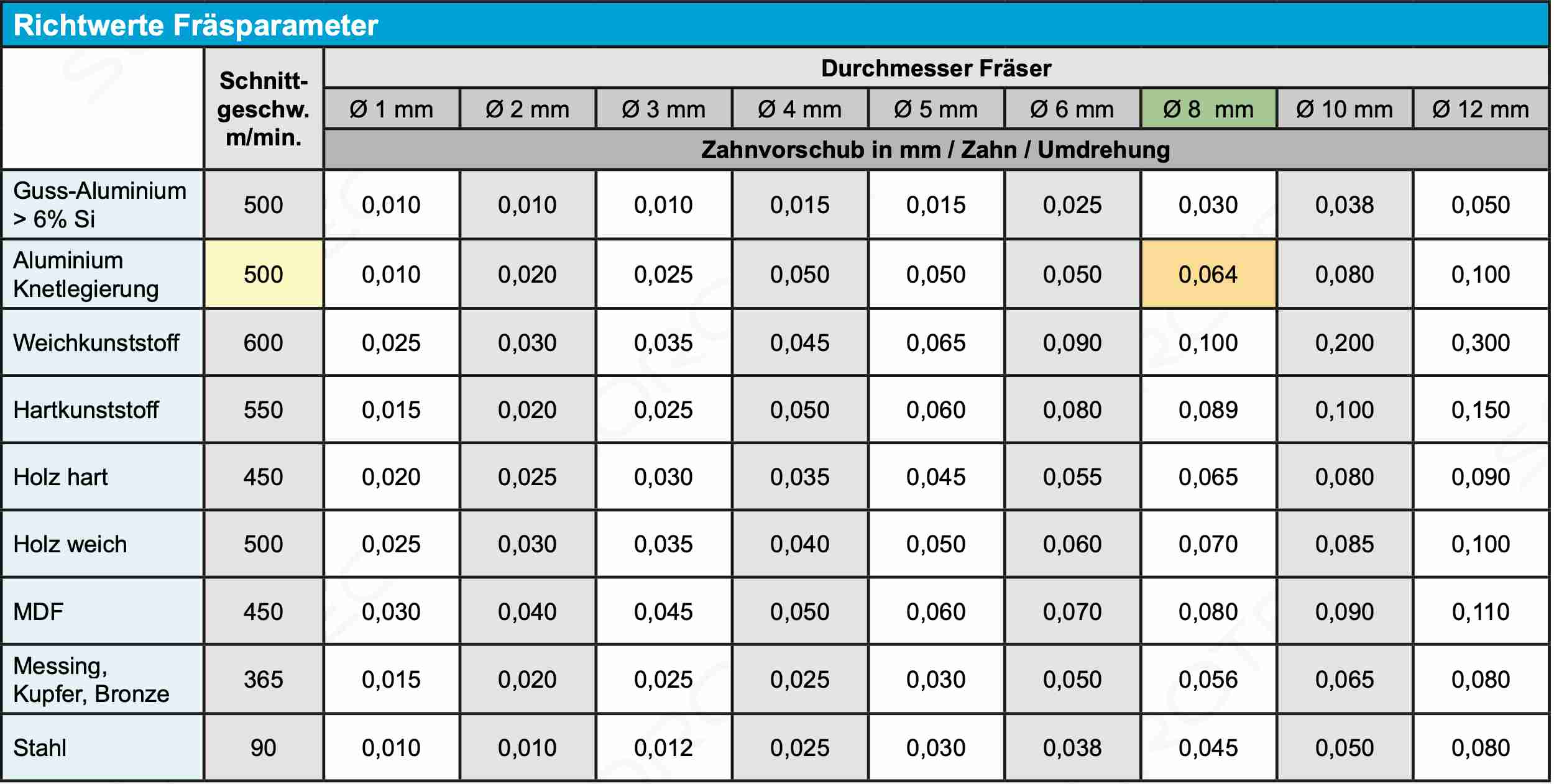
Before entering these values, you need to add a sub-section for the material you are using, in this case softwood. You can then enter these values on fusion, but you should also bear in mind that these data are parametric and that when you change one value, the others change with it. When we enter our feed speed, our spindle speed is 26525 rpm, which is higher than the speed of rotation of the machine, so we will replace this value with 24000, the maximum speed of rotation of our spindle, and work at a slower speed. We can then enter our feed rate per tooth and deactivate the use of the lubricant jet, which we won't need as we're working with wood.
Finally, we go to the post-processor section and change the spindle number. Our machine has 8 milling cutter slots, so if we don't enter the right one, it will want to change at the start of milling. Once we've finished, we can validate and move on to the next stages
CNC fraise
There is a site called CNC fraise which sells milling cutters and which also offers a table with different parameters. It shows this page which explains how to calculate the various parameters with precise formulas and which contains a pdf file and an excel file where you can find the default values and which proposes speed values half as fast as those of the manufacturer. In my case I used the Sorotec manufacturer's parameters.
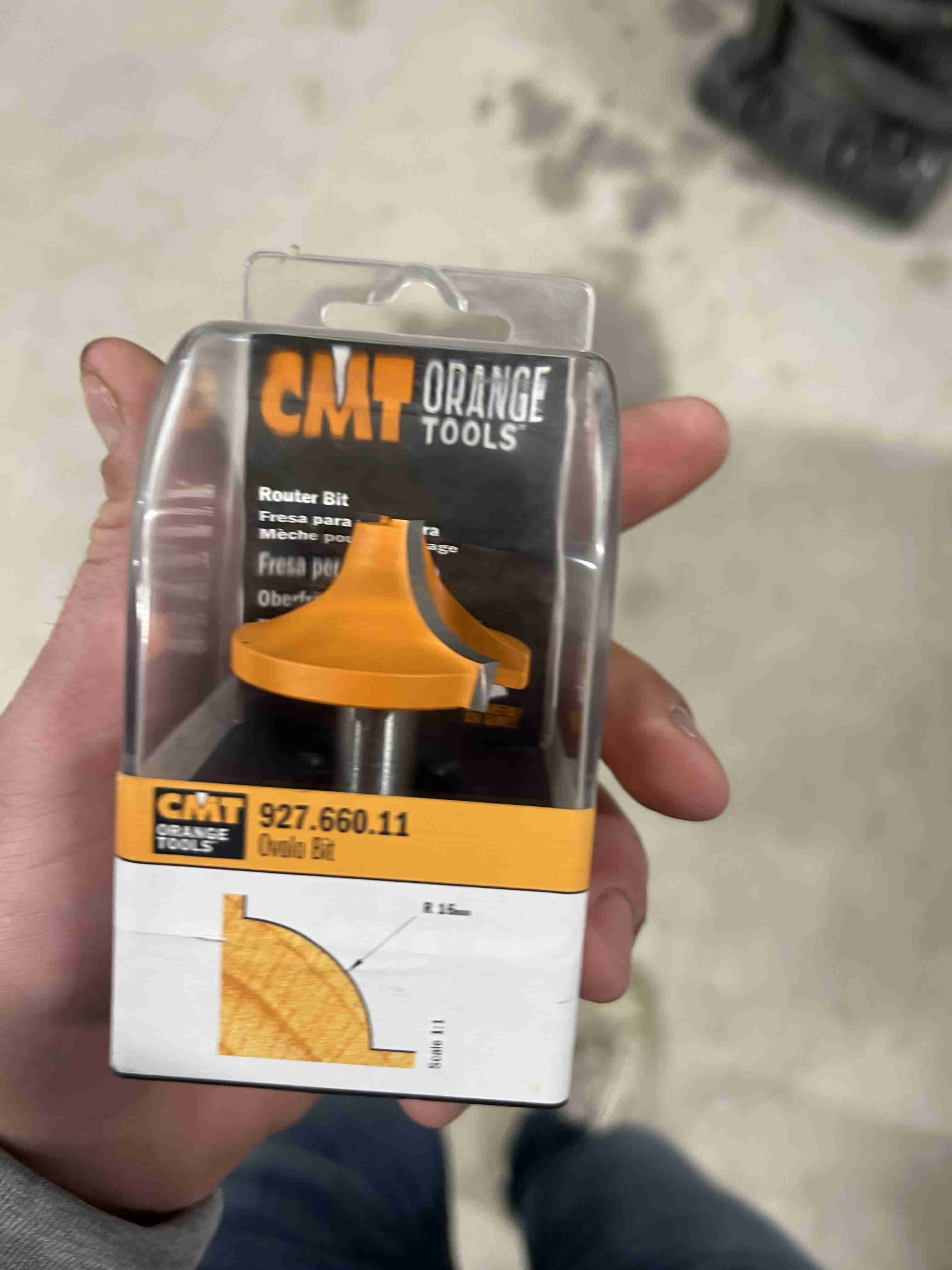
Radiation cutter
As for the radius cutter, I had more difficulty preparing it because I couldn't find any documentation on it. I did have the various values for width and radius height on the website, but there was nothing on the manufacturer's website. CMT Orange Tools, about cutting speeds and feed per tooth. One of our instructors recommended that I use the same cutting speed as for a 6mm milling cutter, according to the CNC Fraise values, i.e. a cutting speed of 250m/min and a feed per tooth of 0.0868 mm.
cutting
Once we have prepared our cutters, we can then prepare the cut-out. To do this, go to the 2D tab and create a 2D contour.
First, select the cutter you want to use and all the cutter-specific values will be updated. Then, in the geometry sub-menu, we select the underside of our design, which corresponds to the contour that the cutter will make. We can then add tabs to our design so that our elements are held in place during cutting. In the heights tab, we're going to modify the height on the bottom to add an offset of -1mm to compensate for any irregularities in the material. We can then go to the pass tab where we'll first add multiple depths so that our cutter doesn't try to cut everything at once, and we'll enter the diameter of our cutter as the pass depth.
Finally, you can go to the link tab and uncheck inputs and outputs. Our outline is now ready
In the case of my escutcheon, I added a roughing pass to remove as much material as possible for the second cutter, so I added a 4.5mm overlap with two overlaps.
For the second cutter, I added a 15mm Z offset so that my router doesn't damage the mitre bars and doesn't have to bend down or stand up when it passes over them.
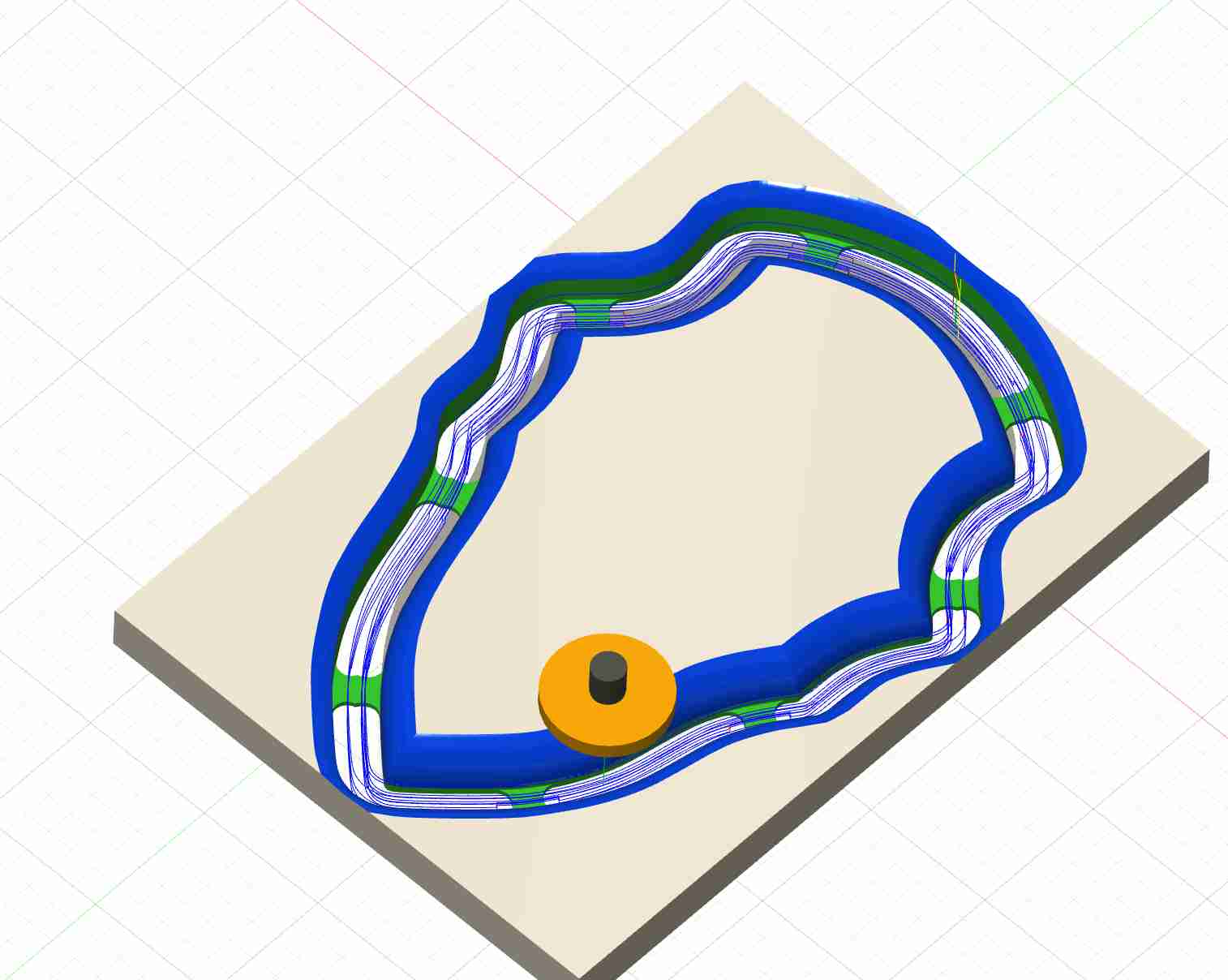
Using the simulation tab, you can see the different stages of cutting as well as the final result. Here's what I should get when I'm done cutting
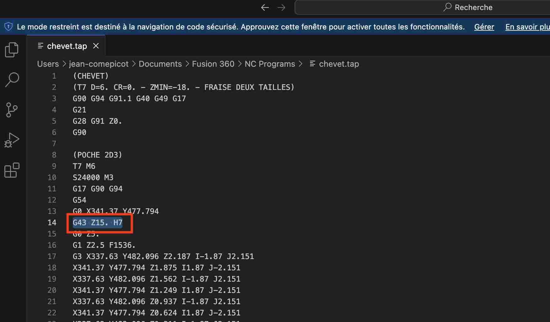
Now that everything is set up as it should be, we can go to the post-processing tab and enter the post-processor in our case Mach3Millon can then enter the name of our file and we can choose to open the NC file in the editor in order to modify it. Finally we can click on Post-processor.
The file will normally open in our code-editing software, in my case visual studio code or I could modify the code. A command line generated in the code should be removed, as it causes problems for the machine as it is not necessary. This is the first line starting with g43. Once deleted, our code is ready to be imported into the machine.
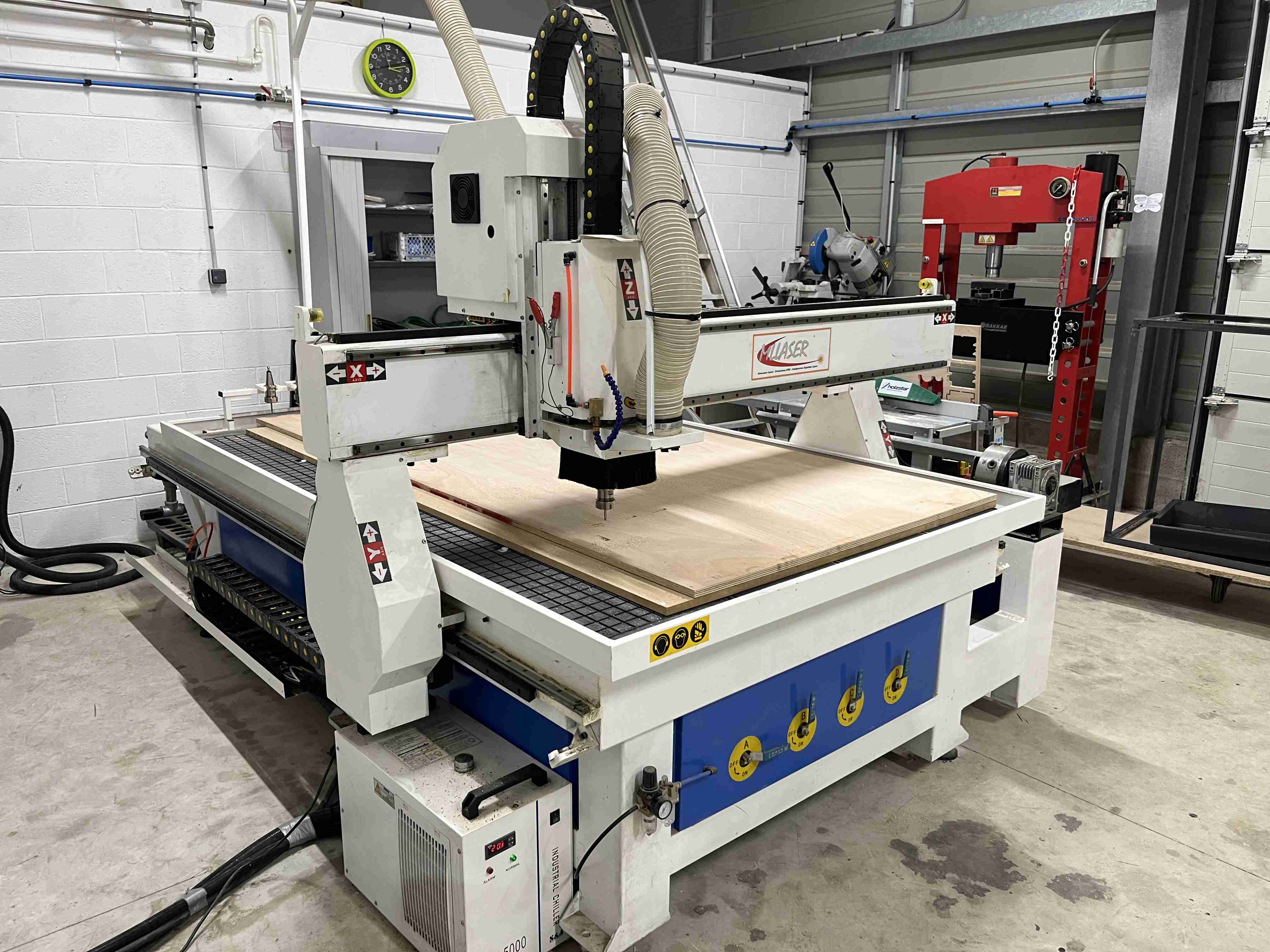
The machine
The milling machine we use is a 3-axis CNC from ML Laser, with machinable dimensions of 1500 x 2400 mm. It has an automatic tool change system with 8 different cutters, a cooler for the spindle motor, a dust collecting system and a vacuum table. You can find Agrilab documentation here
Safety
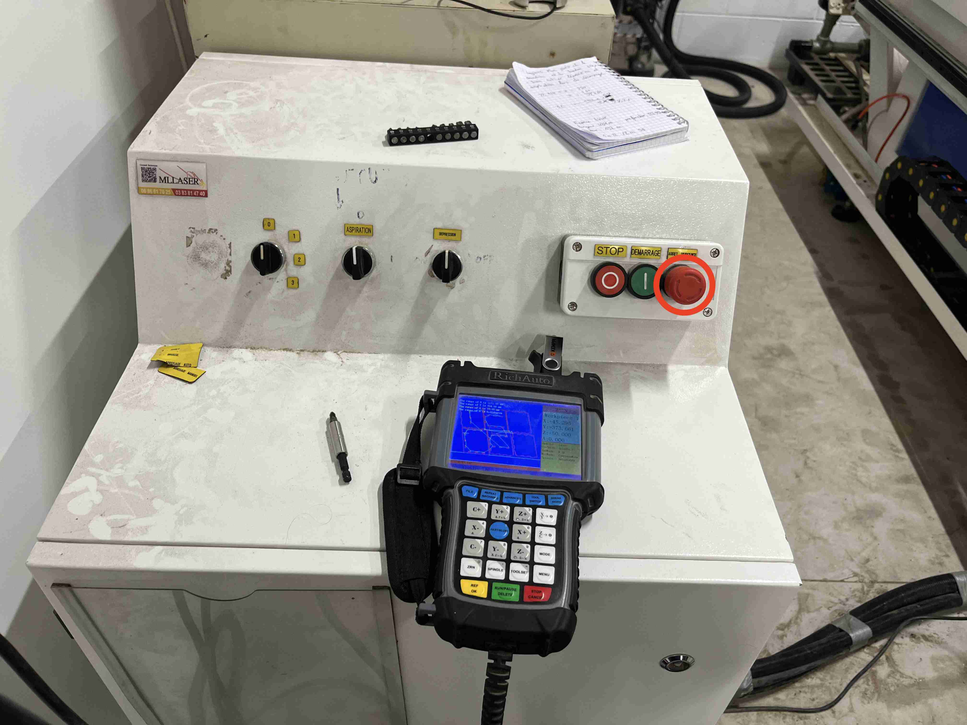
The most important thing before using the machine is safety. Even before turning it on, we must check that nothing can collide with any of its axles and that it has plenty of clearance. It's also essential to wear all the necessary safety equipment, at least goggles and ideally a helmet and gloves. When using this machine, it is essential to be near the emergency stop button to stop the machine if anything happens.
Utilisation
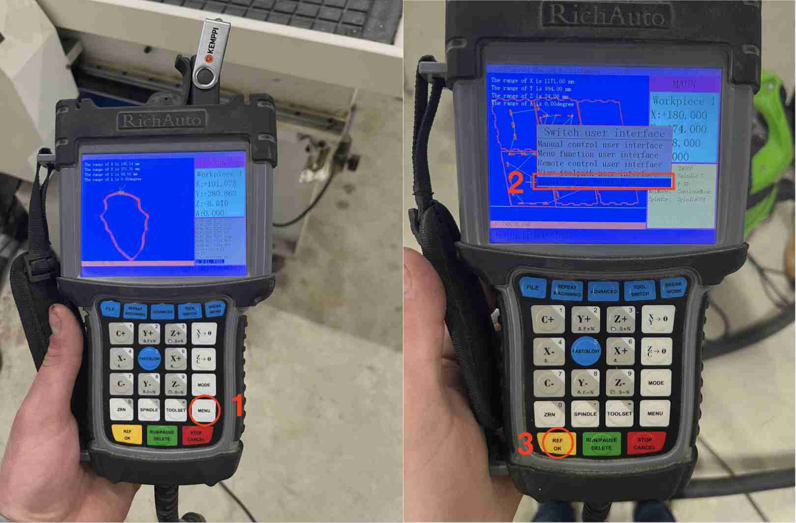
To use this machine, you need to carry out a number of steps in order to use it and carry out the safest and highest quality work possible. The first step is extremely simple: simply check that there is nothing lying around the machine and make sure that it cannot collide with anything, whatever its position. You can then switch on the air supply to power it. You can then bring along your equipment if it's not already on the sacrificial layer. All you have to do is lay your board flat and fix it to the sacrificial layer, which is a sheet of MDF, so it's safe.You can then select the mill you want, by clicking on toolswitch and then numbers 1 to 8 depending on the milling cutter you want.
We can then start making our origins. To do this, simply move the X, Y and Z axes using the buttons allocated to them. Once our cutter is at the desired origin, we can click on the XY->0 button. As far as Z is concerned, we're going to position our cutter as close as possible to the centre of our material, so that it is as precise as possible with the irregularities in the board. Before making the origin, we need to set up the suction table, which will suck the air onto the table to press our board and the sacrficial layer against the floor. Our machine has an automated system for making the Z. All you have to do is connect the + clamp to our milling cutter and connect a dedicated tool to the top right of the Z axis. Once everything is connected, you simply position the sensor under the milling cutter and press Toolset. It's a good idea to test in a vacuum beforehand, in case you forget to connect the clamp or if there's a false contact, to avoid damaging the sensor. If you want to make an air cut to test our file, this is the time to do it by setting a Z higher via the sensor or by selecting ZC->0 on the remote control when the cutter is above.
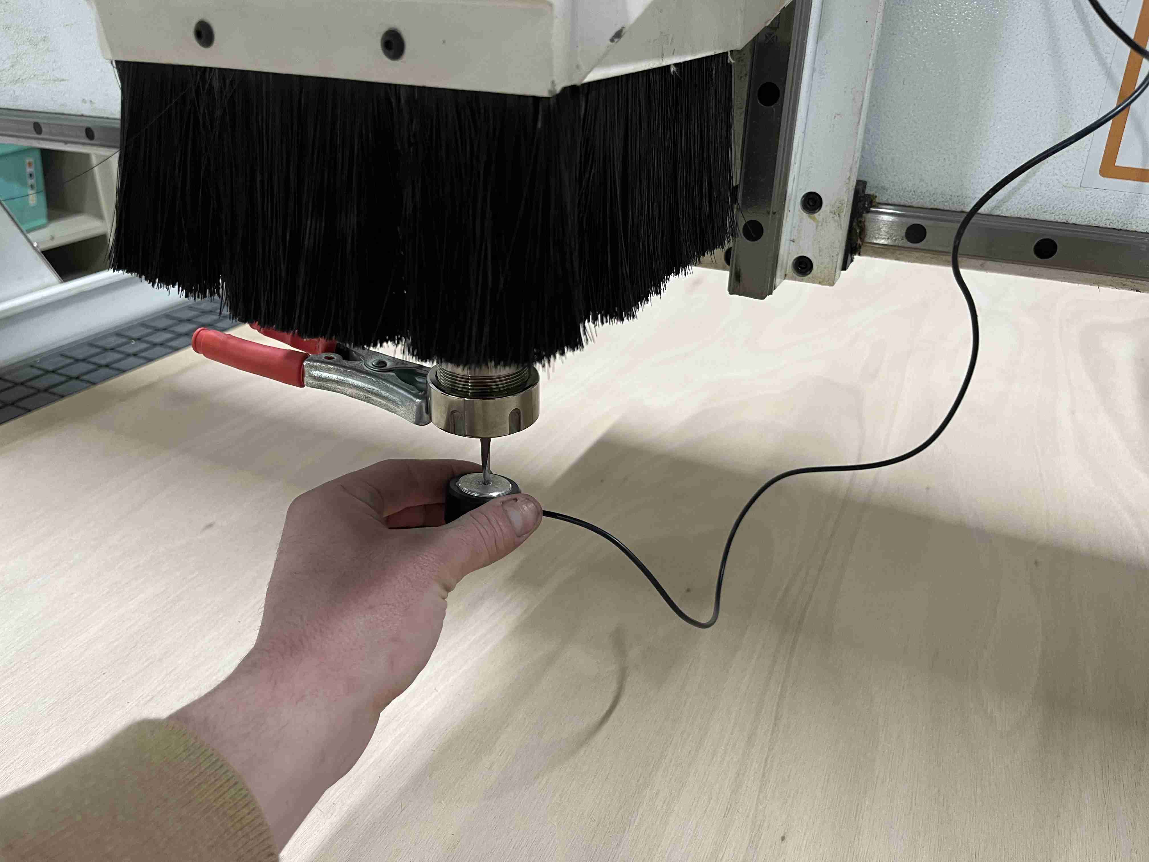
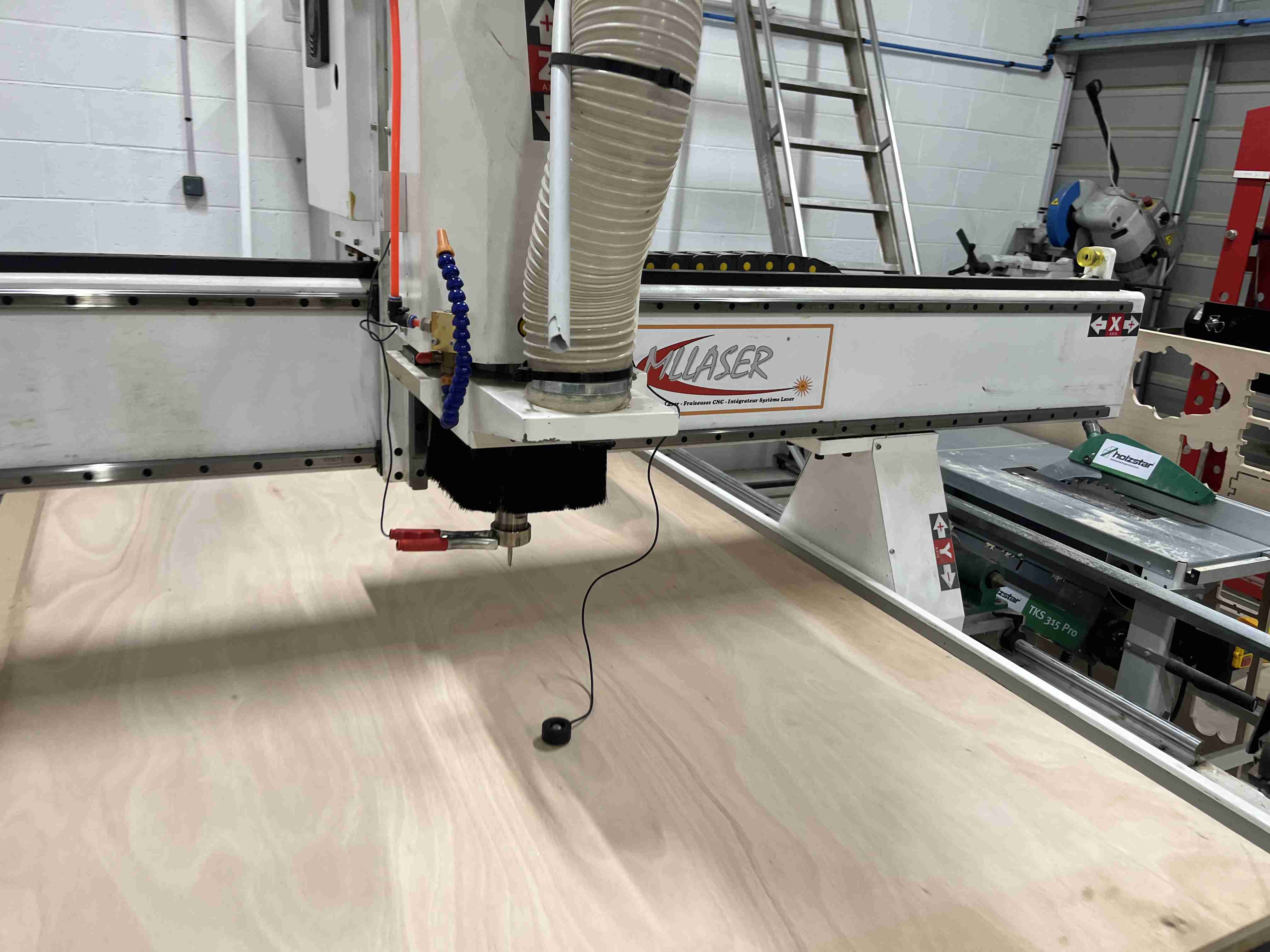
On our machine we also have a brush that allows us to keep the sawdust in place and suck it up more easily, and it also has the advantage of providing a little protection should any debris fly out. Unfortunately, the brush is systematically disconnected when the file is changed, so it's necessary to go to the Menu > Input output control user interface > Select the number 6 of the third line with the green button > Menu > Manual control user interface.
Once this stage has been completed and the file has been added to the remote control's USB key, it can be loaded by clicking on File and selecting our file. We can put on our safety equipment, i.e. goggles and helmets. Then all we have to do is switch on the suction, lower the brush, press the green button and then the yellow button to start cutting.
We'll then have to stay close to the machine throughout the cutting process to make sure there are no problems whatsoever. For added safety, we'll need two students to keep an eye on the machine in case anything happens.
For my crest I loaded two gcodes, the first to cut the crest with the 10mm cutter and the second to cut it again with the radius cutter. Everything went off without a hitch and the result was quite satisfactory. If you want to reproduce it, you can find the link to the fusion file here.
Project
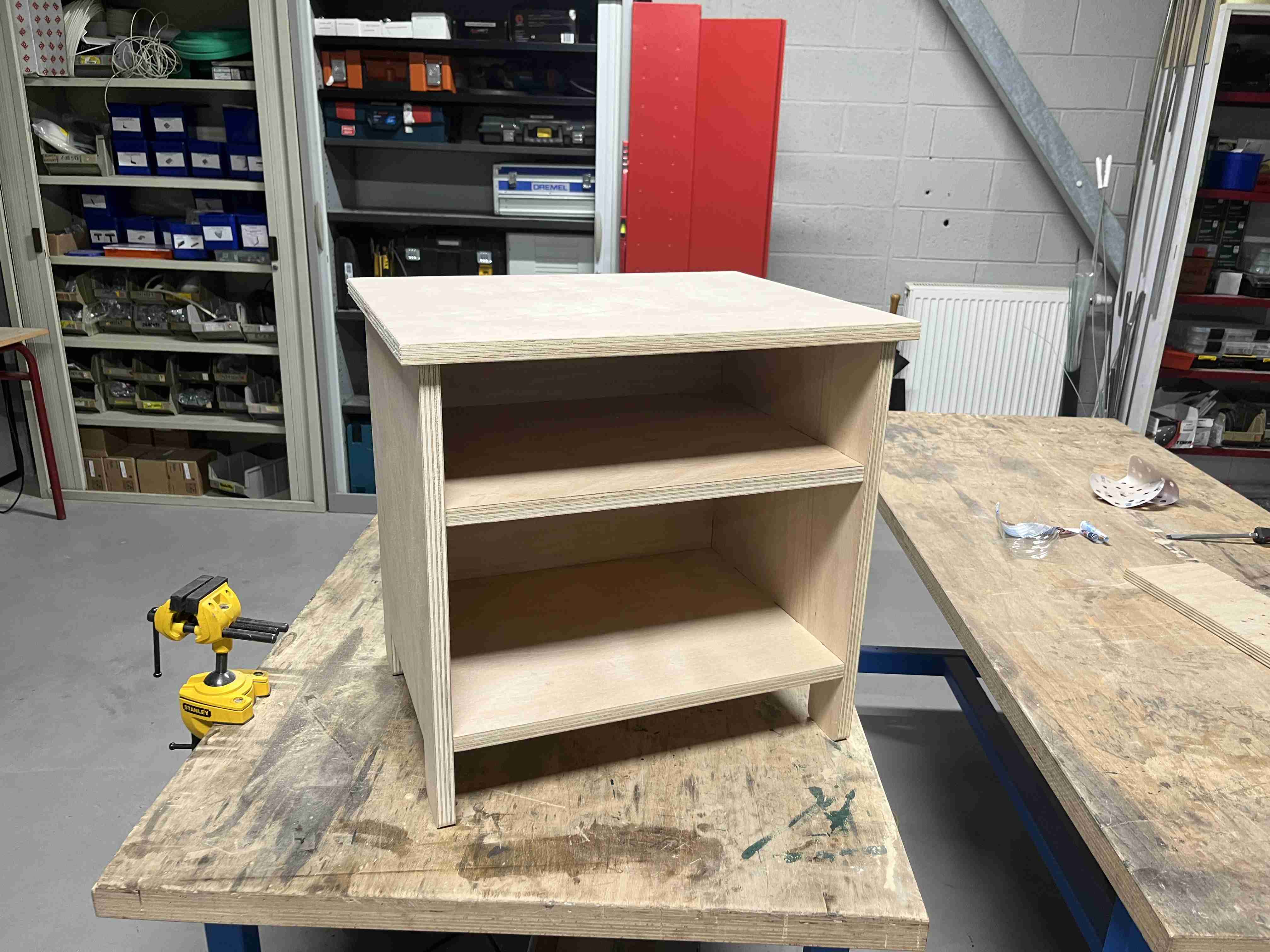
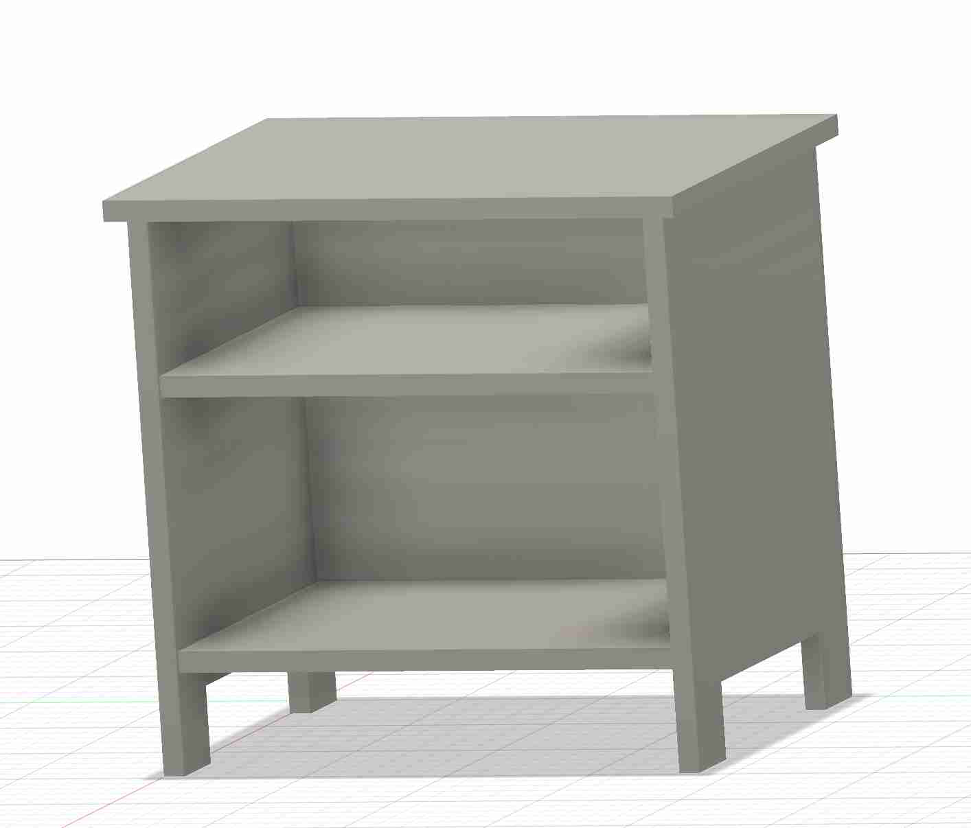
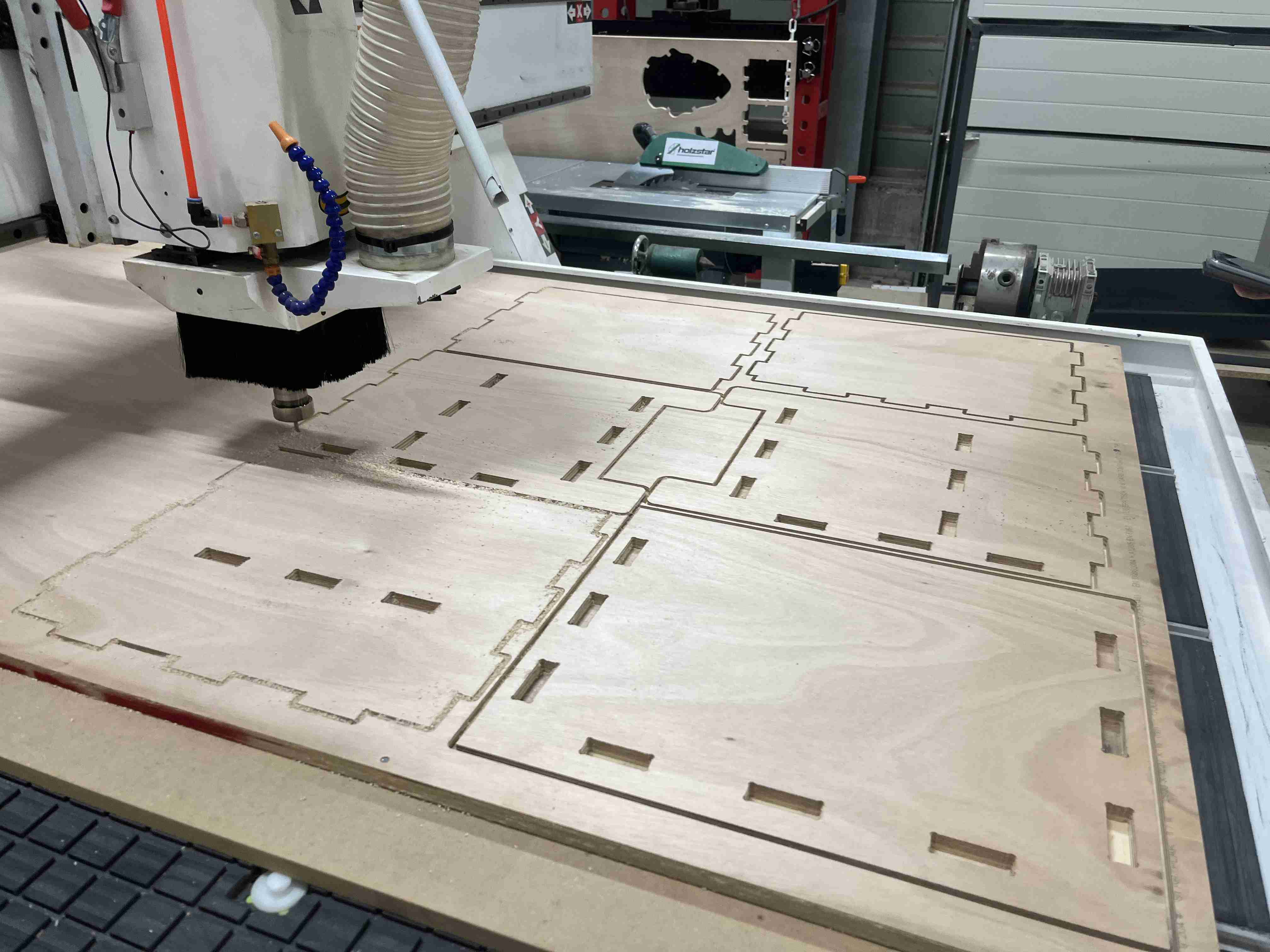
After doing this, I already had a better grasp of the machine and how to use it, and I looked at our assignments, which aim to design, mill and assemble something to metre scale. It took me a while to work out what I was going to do, but in the end I decided to make a bedside table because I don't have one. Once again I used fusion 360 to design the table. As this construction is made up of multiple boards, it's very important to create one component per board so that you can separate them all individually. I made sure that the table was parametric so that it could be widened or lengthened according to need or existing space - in my case, the table measures 500 x 400 x 484mm. So I created the different pieces one by one, creating projections so that I always have the same values wherever I place myself.
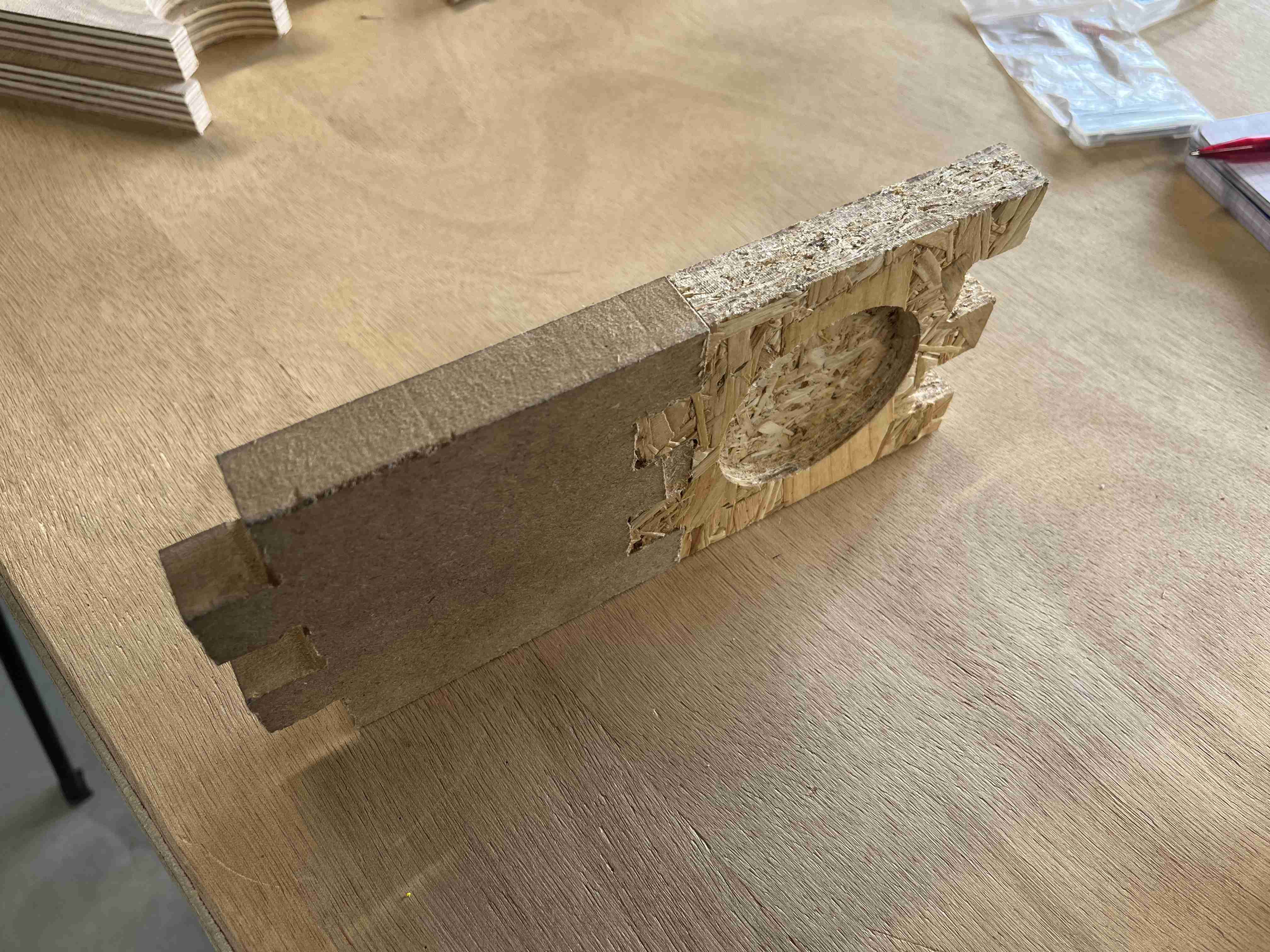
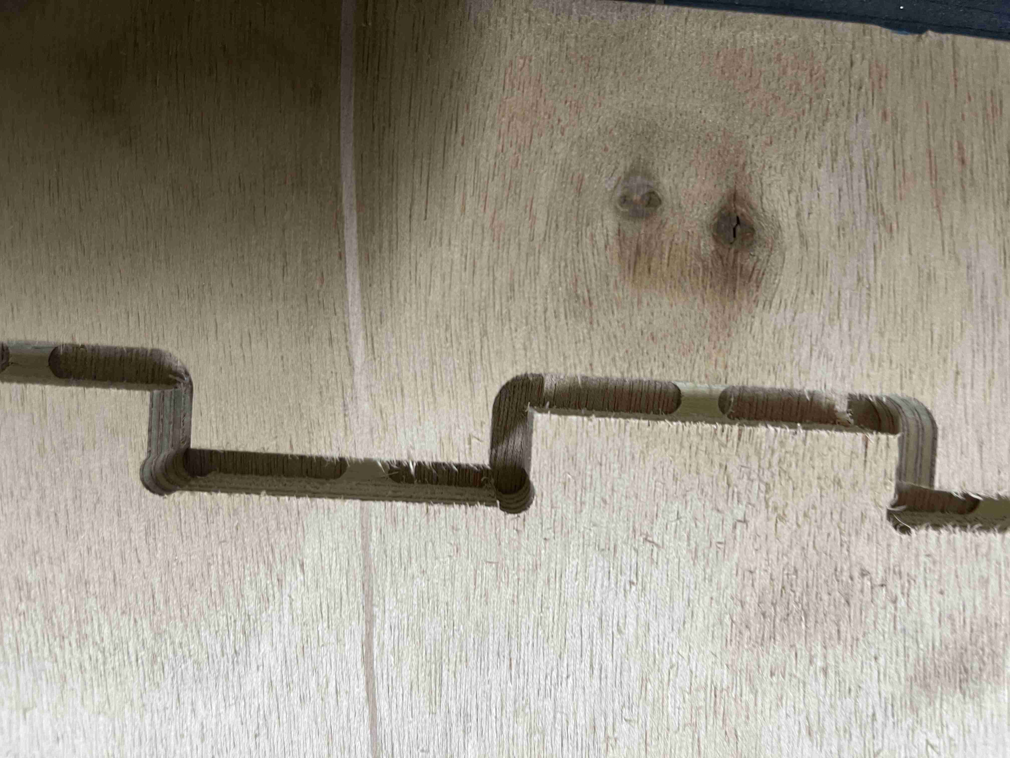
Once you've created the table with its various interlocking parts, you'll need to add some Dogbones so that the interlocking parts fit together properly. As the milling cutter is a rounded object, in order to press a square shape into place, it needs to overhang so that it leaves enough room for the corners. To do this, you first need to download the Github Plugin, which you can find at here, On this page you'll find the download link and the steps to follow, whether you're using Windows or Mac. Once you've downloaded the plugin and relaunched fusion, you'll normally see the tool appear at the top of the create menu. It's very simple to use, just select one of your components, choose the dogbone tool and select a face, then enter the diameter of your cutter and all the dogbones will be generated automatically when you click OK.
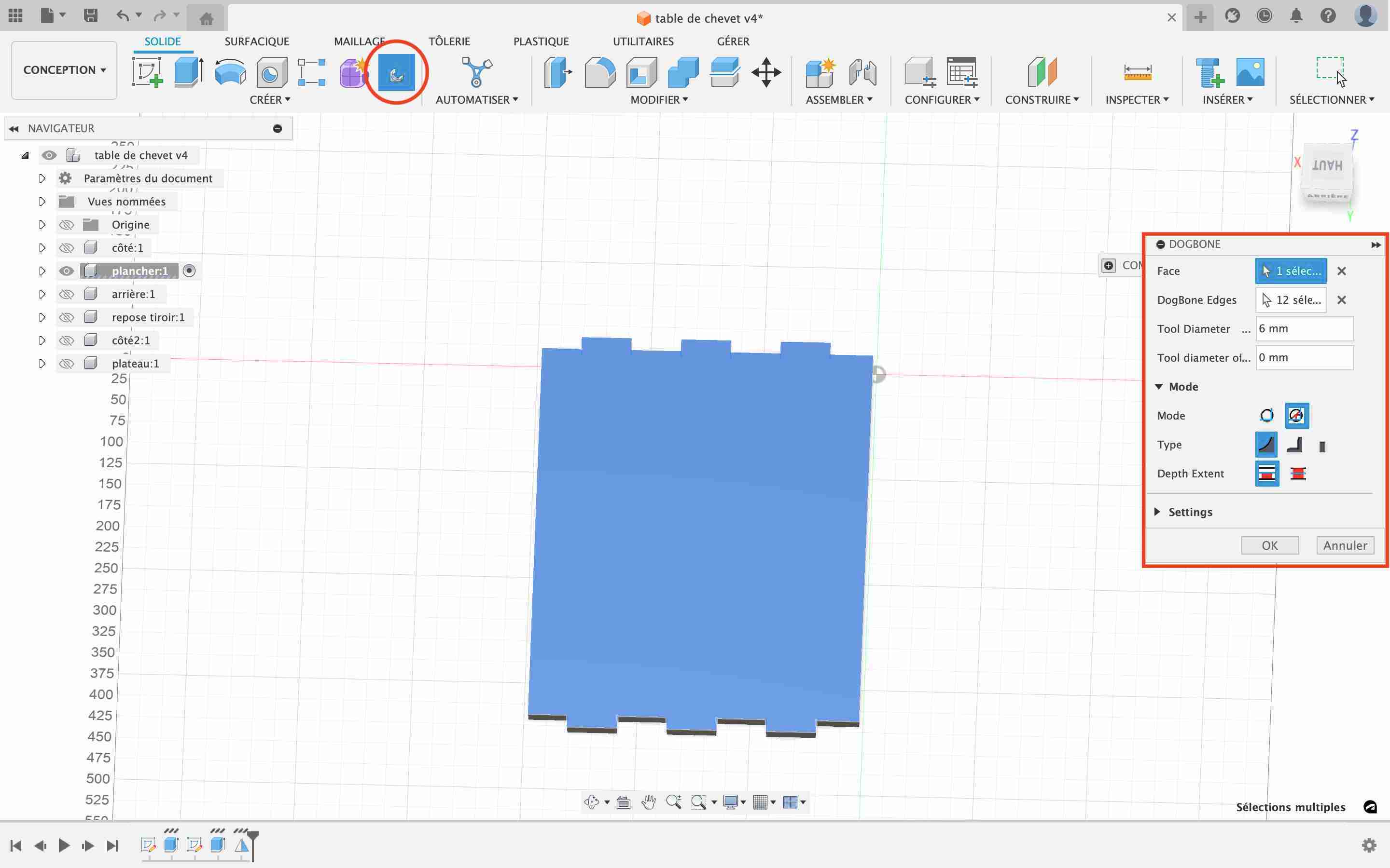
In my case, I even had to remove some by extruding the cut part because I didn't want it to put any on the corners of my table legs (I could also have tried to find where these two dogbones were in the function but I don't know if I'd have been quicker). Once all our dogbones have been added, we can prepare our design for manufacture. As far as the clearance is concerned, I chose not to use any because I found that the joints were quite rigid during our tests with the same thickness of wood and I wanted something rigid enough so that even without glue, the table wouldn't come apart.
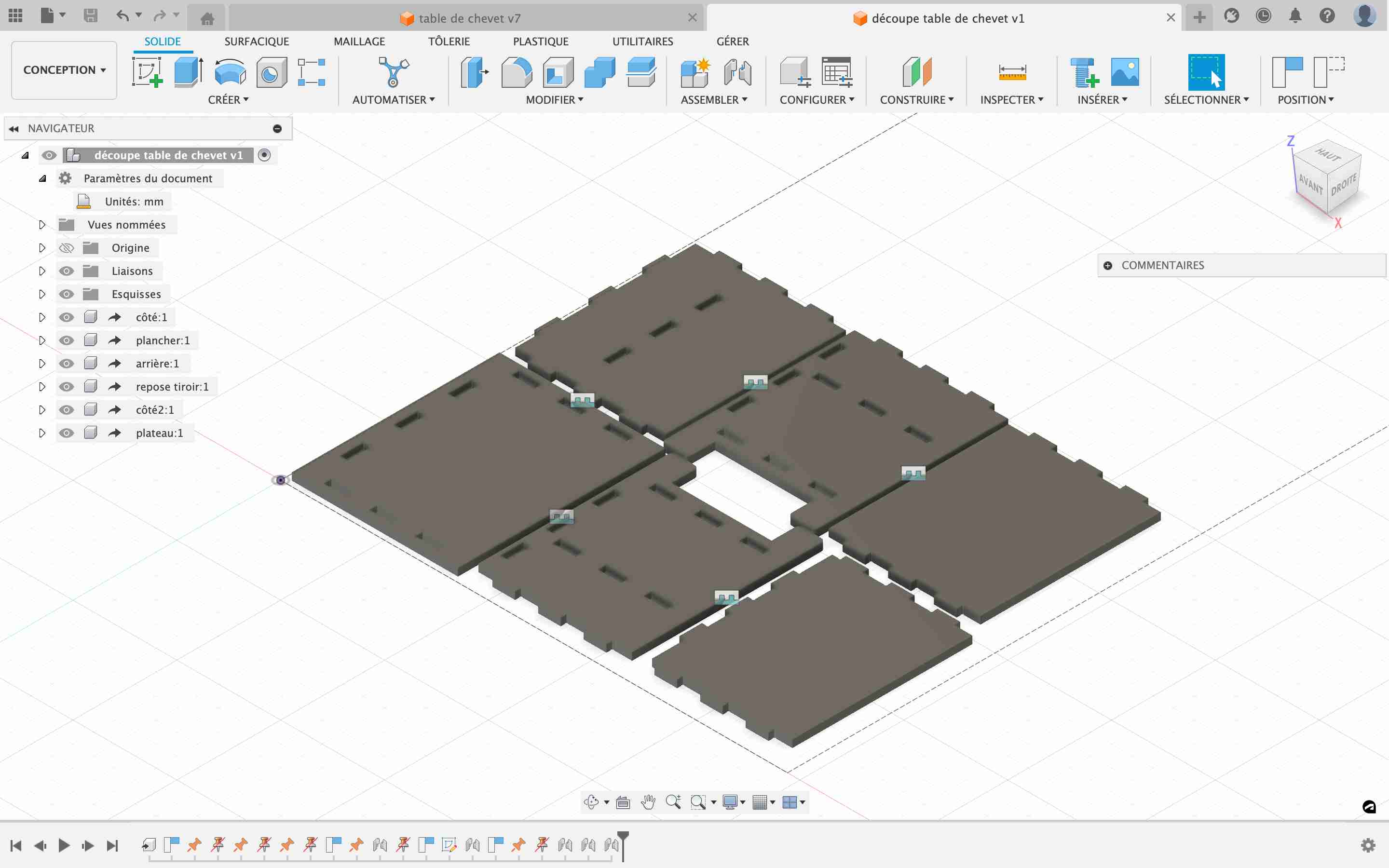
To start manufacturing our object, we need to begin by deriving it in a new design. To do this, select all our components and click on "Derive". This function will allow us to have a second design attached to this one, so if we wish we can modify the design of our piece of furniture, which will also change the parameters of the cutting file. You need to make sure that you're in online mode when you do this; I was a bit slow to realise that I couldn't because I didn't have a good internet connection.
Once our files have been derived, we can then go to the new design and define one of the elements as the ground, so that it is fixed. We will then make multiple connections to position them all in place of each other so that we have a group of elements positioned flat. You need to be careful when placing them to put the faces with pockets facing upwards so that they are accessible to the milling cutter.
The pockets
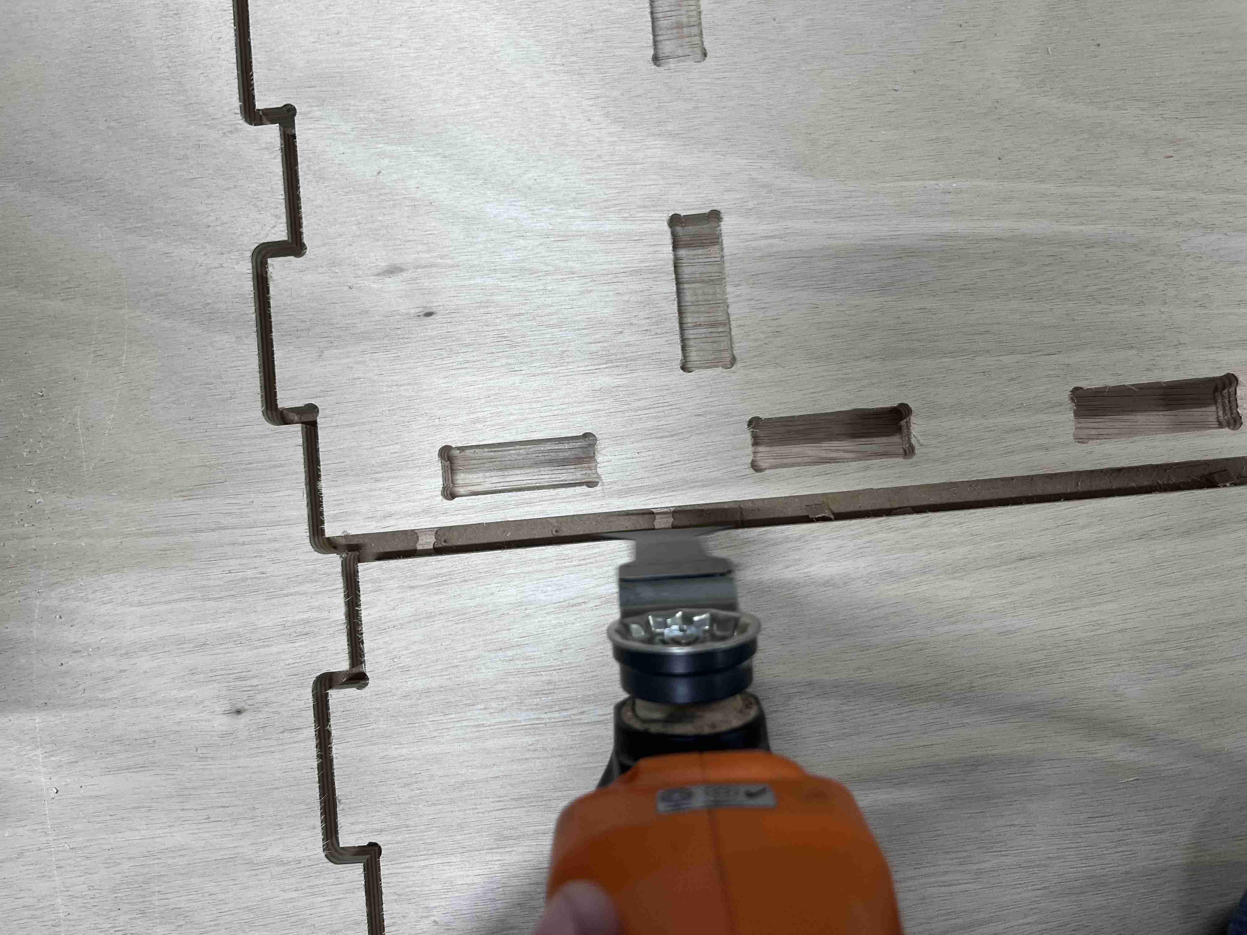
Once all the elements have been positioned correctly, we can move on to fitting them in the same way as for the crest, but for this design we have pockets, which are a different operation. As with the 2D contour, we'll go to 2D and then create a 2D pocket. We're going to enter the parameters of our cutter as for the contour. In the geometry tab, we select our pockets. Make sure you select the bottom of the pocket, if there is a red arrow, it is the top contour that has been selected and the pocket will not be milled. Then in the pass menu, we'll enter an overlap of 2.7mm (45% X diameter of the mill) and a maximum roughing depth of 6mm (diameter of the mill). Be careful to deselect the allowance, it is saved by default when you make a pocket but it will modify the depth of our pockets and in my case, it blocked the appearance of the dogbones. When you create your layout, you need to make sure you do the layout before the contours so that the board is as fixed as possible. Similarly, if you have to make cut-outs inside a room, it's best to cut the inside first and then finish with the contours of the room.
I encountered a number of problems when cutting this piece of furniture, which were solely due to poor preparation of my fusion file. Firstly, my milling cutter was going to change tool as soon as I started cutting, it took me a while to understand why I was having this problem when my milling cutter was programmed in the right place, in reality, when I created the tool I put it in the wrong place, and when I subsequently modified the parameters of my milling cutter, it always stayed in the same place, I had to select it again with the updates I had made in order for it to work. Then, I had my problem of excess thickness which caused my pockets to be too thin and which prevented the dogbones from being cut. Finally, on the last layer of the contour cut, I had forgotten to add a 1mm margin which caused the layer to cut incorrectly. On the edges where my board was fixed by the screws, the cut was well done, but on the inside, this layer wasn't cut. To remedy this problem, I removed the multiple layers so that there was only one pass and corrected by setting the correction to 1mm.
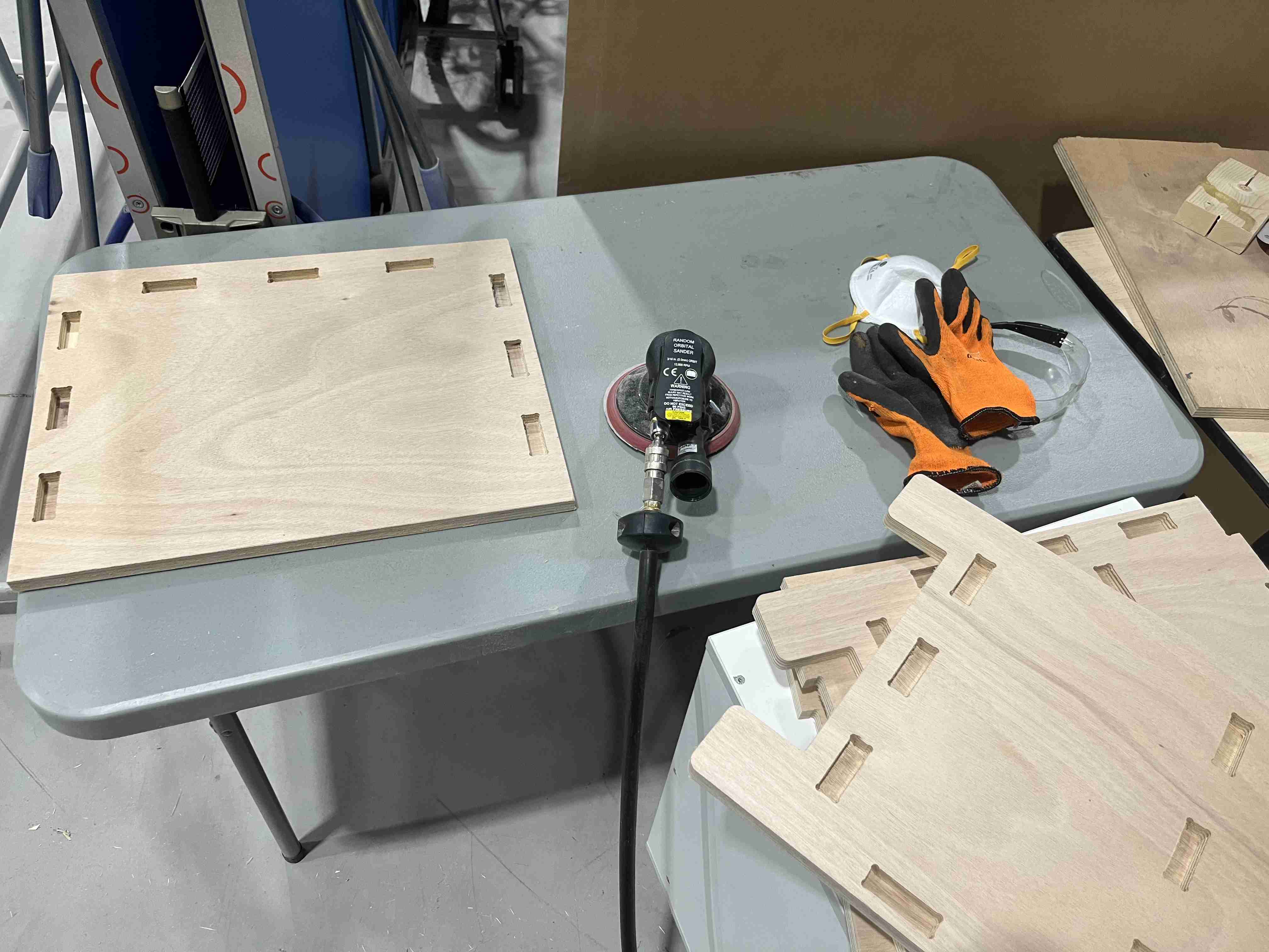
Sanding
Once I'd managed to finish all my cuts, I had to remove the tabs to separate them from the raw material. To do this, we have a multitool at Agrilab, so all you have to do is run over the tabs with it and they come off quite easily.
Once all these elements had been separated, I sanded them to smooth out any rough surfaces and to remove any areas where the cutter had torn the wood slightly. I then sanded them again because I was having trouble fitting them together. A simple pass over the 4 sides of each board made it much easier to fit my pieces together. I would have saved time by setting a chamfer when designing, I would only have had to correct two sides out of 4.
Assembly
Once the pieces had been prepared, I had to assemble the furniture. All the pieces fitted together tightly, without screws or glue, I used a mallet and a wedge that I put between the mallet and the furniture so as not to damage the pieces of wood. Once I'd sanded down the cracks, I didn't have too much trouble fitting everything together and it was still quite solid. Here's the final result of my finished piece of furniture. If you'd like to reproduce it, you can find the machining file here.
You can see that when you don't use clearance, the result is satisfactory and everything is well held in place. In the case of my furniture, the top tray is only held in place by the slots I created and yet, as you can see from the video, it holds its weight very well even without glue or any other means of fixing.
The drawer
I then wanted to create a drawer to fit the dedicated space. I used the same tools and methods as I did for the rest of the cabinet, and you'll find them here. here the cutting file, with the assembled drawer in the same file as the table.
Mistakes
During this week, I made a big mistake. On Wednesday morning, when I was in a hurry because I was late to do my documentation, I forgot to put the + clamp on when I did the origin of my Z. The milling cutter hit the sensor and broke off. The cutter hit the sensor and broke off.
Design files
stool
test
badge
Bedside table