This 5th week focused mainly on 3D printing and scanning, and our assignments were as follows
group assignment:
- test the design rules for your 3D printer(s)
individual assignment:
- design and 3D print an object (small, few cm3, limited by printer time) that could not be made subtractively
- 3D scan an object (and optionally print it)
Group assignements
The principle behind this work was simple: all we had to do was characterise our 3D printers. As Agrilab has a number of different 3D printers, we each chose to characterise one of them.
PThe following is a list of our various printers and their respective presentations in the Agrilab wiki:
-Prusa i3 mk3
-creality ender 5 plus
-creality cr 10 s5
-Ultimaker 3 extended
-Ultimaker 2 go
-Ultimaker 3
-Form 2 formlabs 2
-Marforged mark two
As far as the scanner is concerned, we have a 3D scanner. Einscan pro shining 3d with industrial pack and a kinect Microsoft
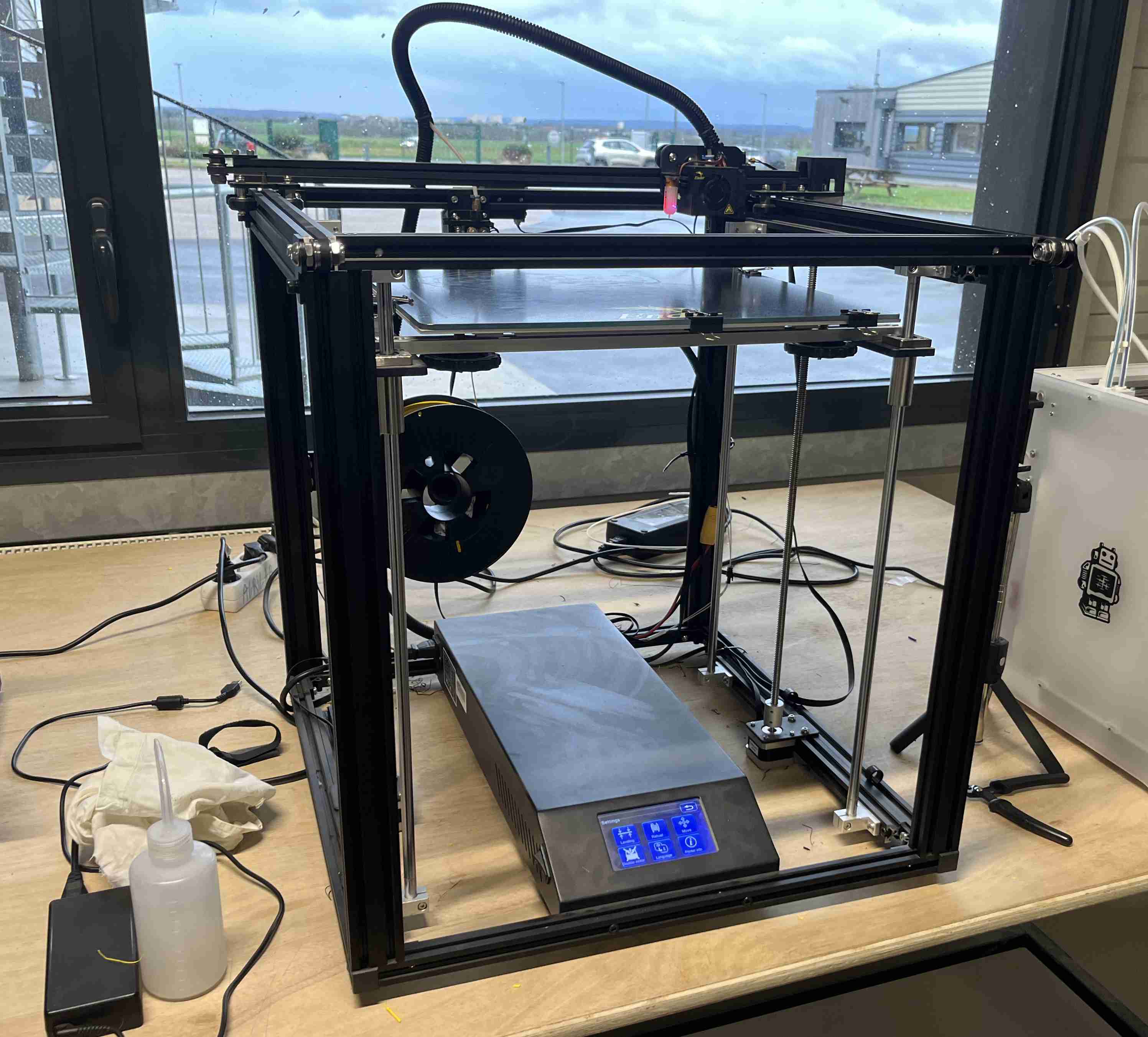
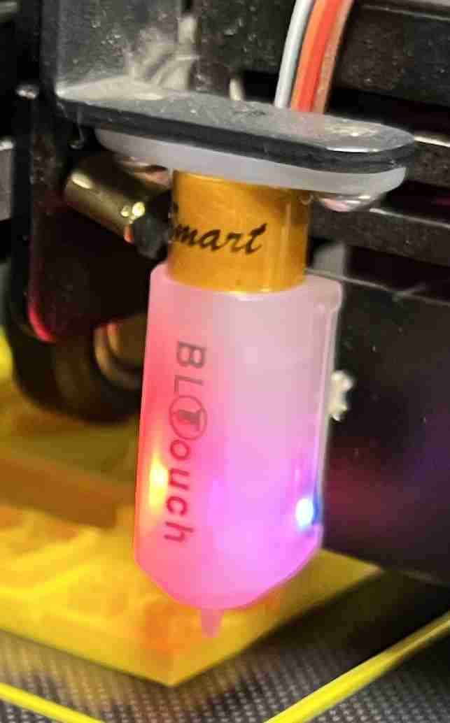
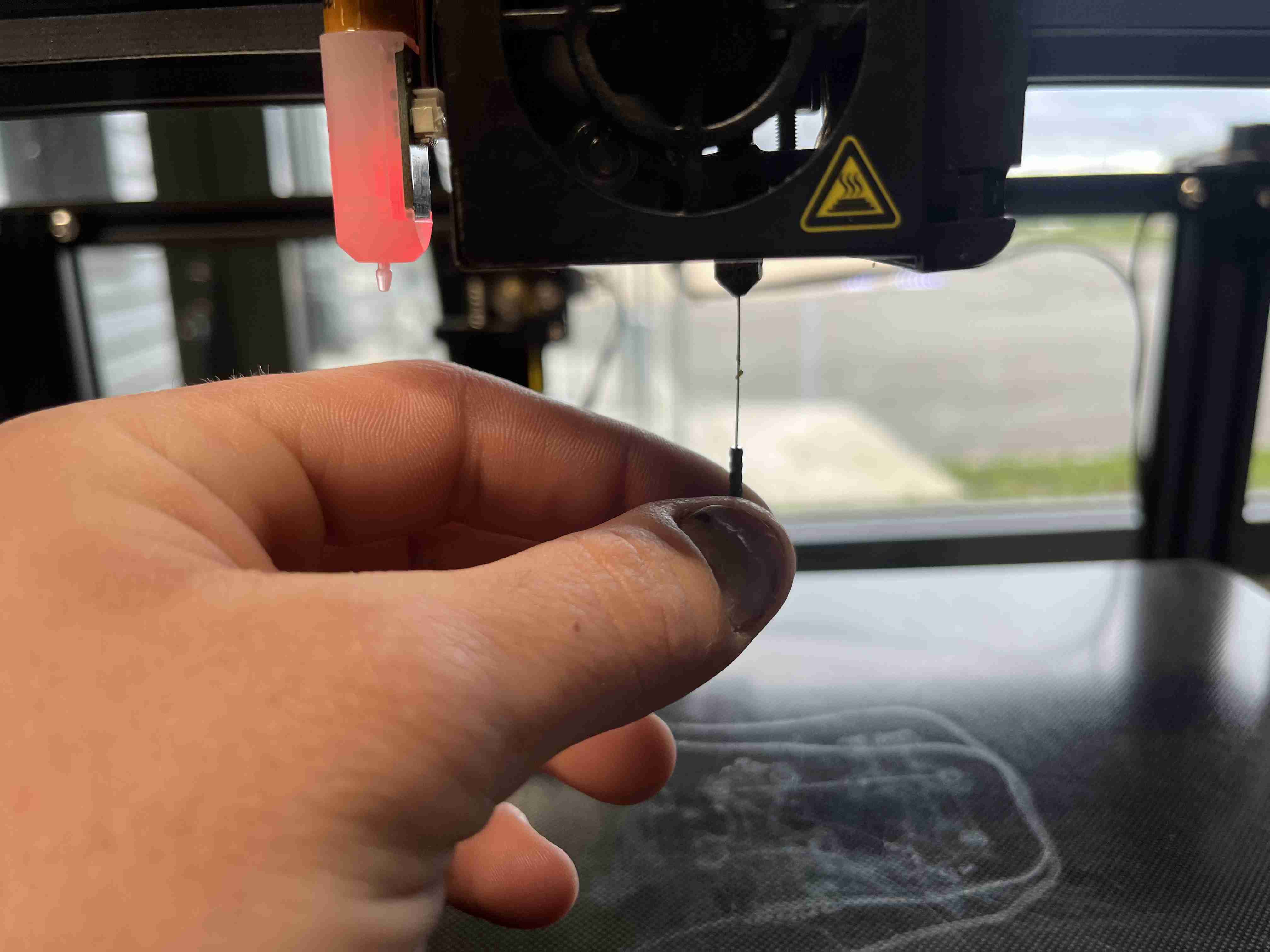
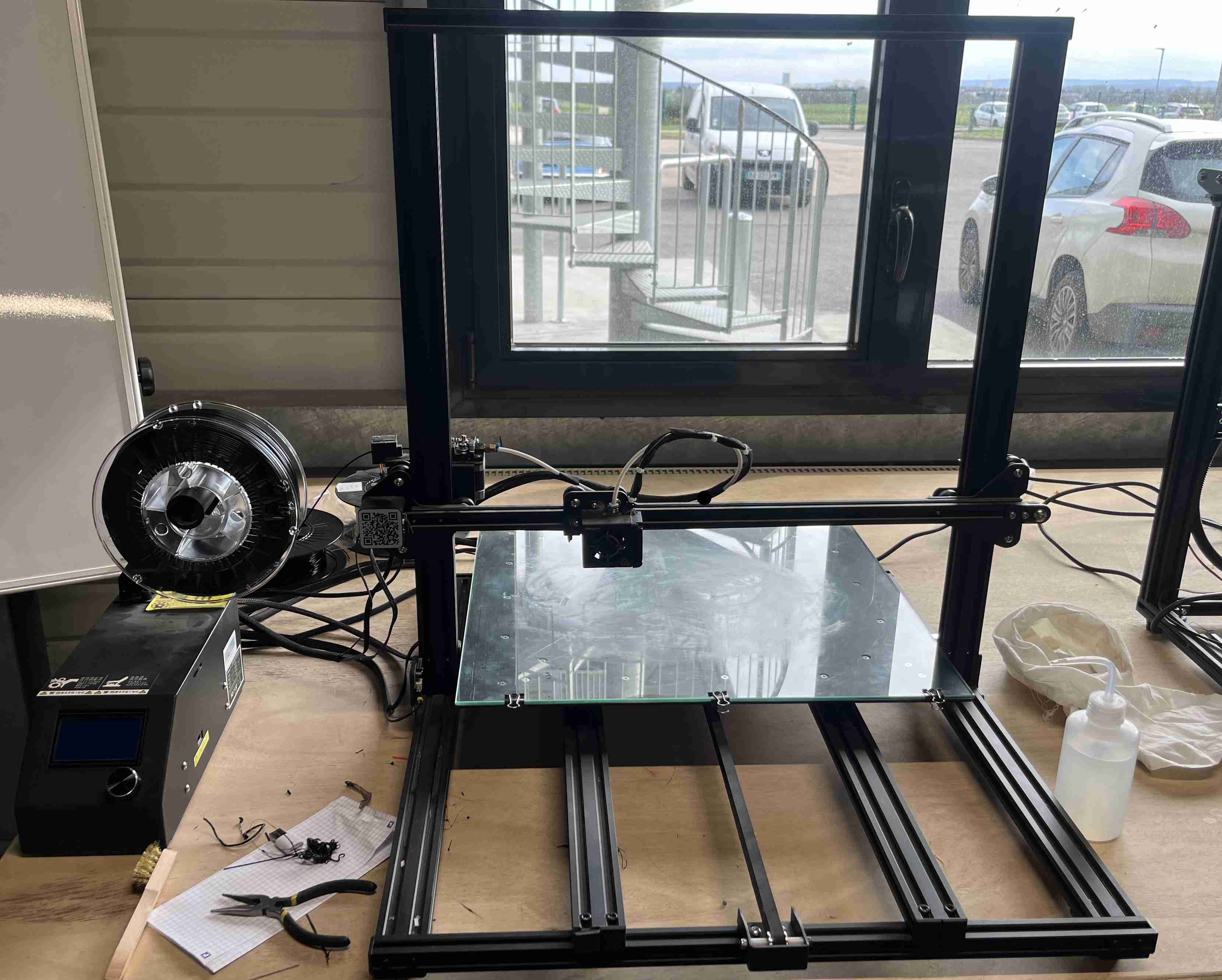
In order to make my group assignments, I personally chose to characterise the Creality Ender 5 plus printer. This is a 3D FDM (filament deposition) printer with a printing volume of 350x350x400mm and follows a Cartesian coordinate system. The X and Y axes are located at the top of the machine on a rail, while the Y axis is controlled by the platen, which moves up and down. This printer is also equipped with a heated platen and a BLTouch. The BLTouch is a device that is placed on the print head and measures the height of the platen. It touches its sensor at different points on the platen, so that it knows exactly how high it is and has fewer problems with the platen sticking. The extrusion of this printer is bowden type, meaning that the extruder is offset unlike others which are direct drive (extruder just before the nozzle).
If you don't have a BLTouch or a levelling device, you can use a conventional sheet of paper, which is usually 0.1mm thick. Folding it in half will give you a thickness of 0.2mm, which corresponds to the conventional thickness of a 3D printing layer. You can move the head on the plate by adjusting the screws on the plate to match the thickness of the sheet.
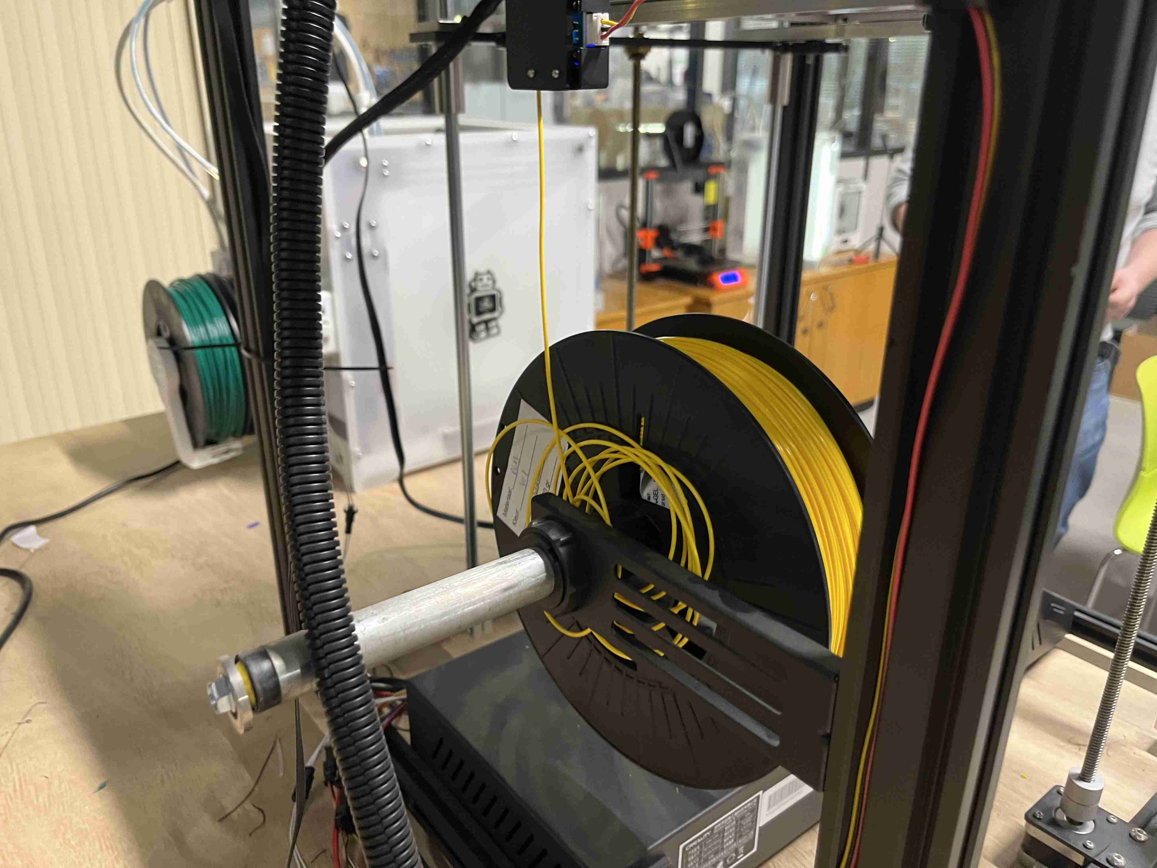
Changing the filament
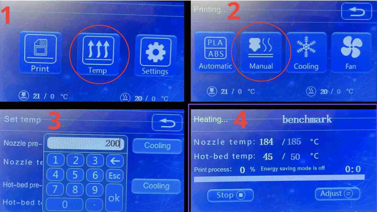
This printer does not have a special function for changing the filament, which can be done by heating the head to around 200°C.
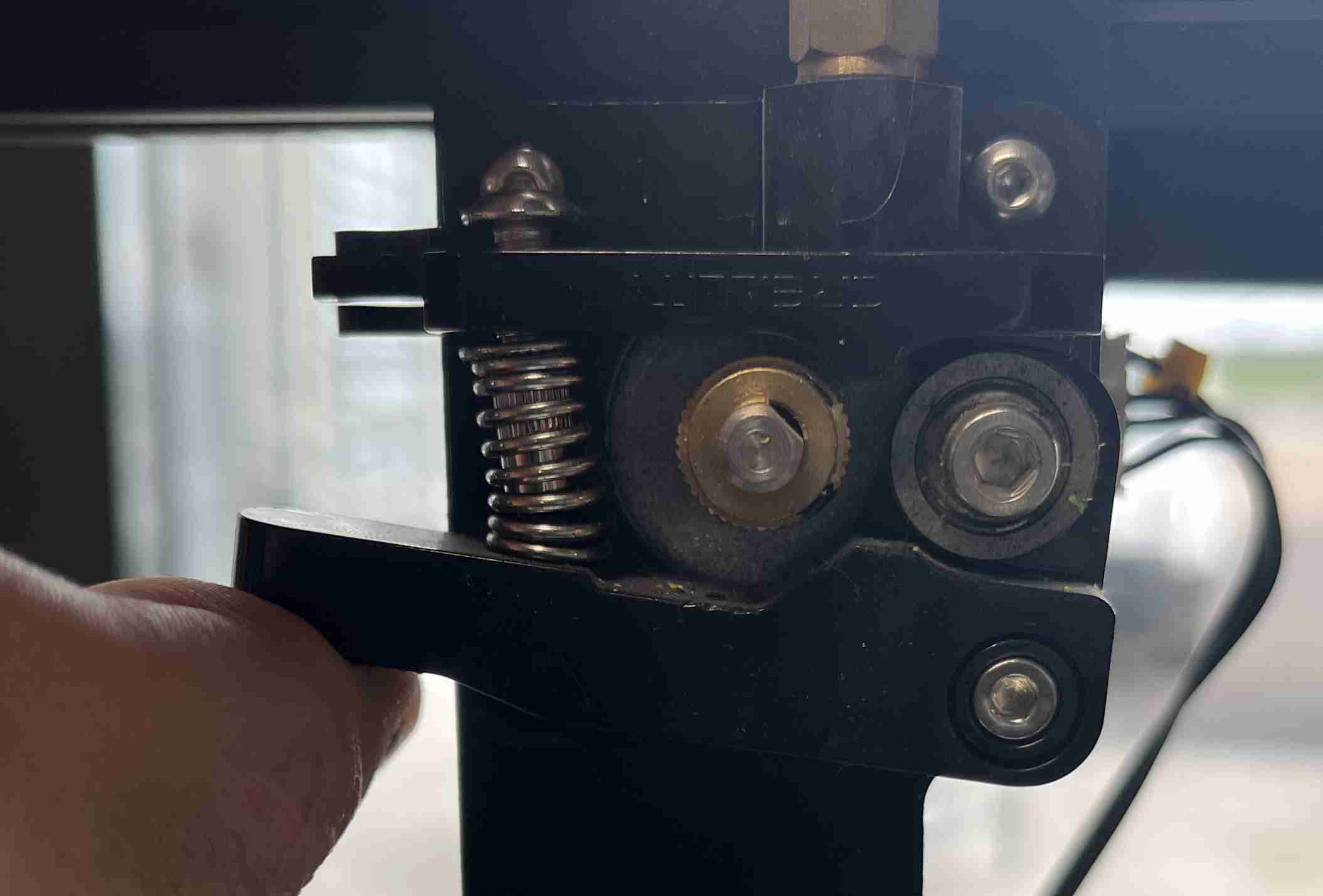
You then press down on the extruder handle with your hand so that the filament is no longer held by force in the extruder pulleys. If the head is hot, you can simply pull on the filament and it will come out by itself; the same goes for putting in a new one, you just have to push until the filament comes out of the nozzle in the right quantity and with the required colour. It's a good idea to cut the filament into two pieces for easier loading.
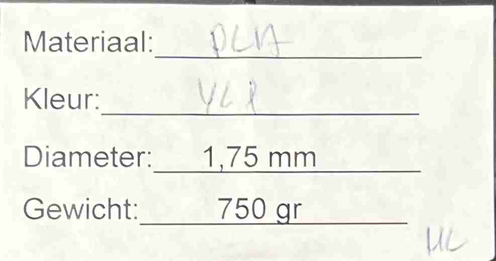
Regarding the filament used, it's a 750g PLA (polylactic acid) spool, yellow in colour and 1.75mm in diameter. I have no other information such as the brand or model. This batch comes from a reel received by Agrilab but from an unknown origin.
Benchmark
To test a 3D printer, there are ready-made designs to judge the quality of the print. We know, for example, the famous Benchy, which is sometimes even the default on printer SD cards, but it only gives information through its physical appearance and not with measurable data.
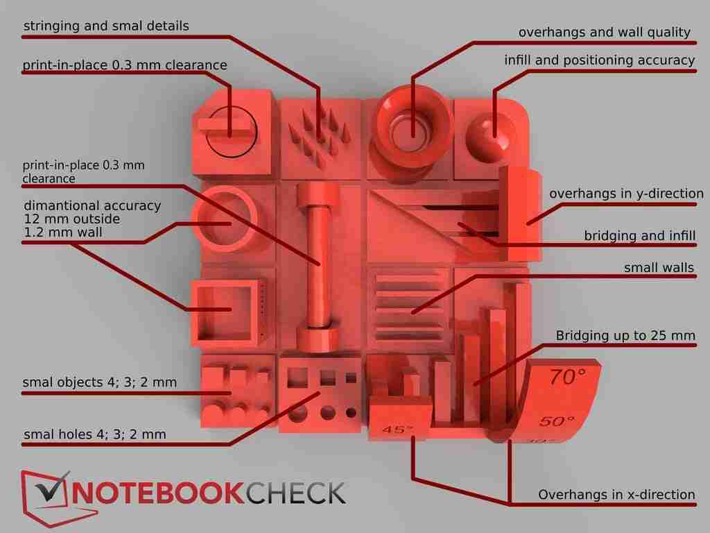
Other benchmarks, like the one I've done, are more representative and allow you to test different shapes such as angles, clearance and details, as is the case with the design I've chosen to use. I went to thingiverse and downloaded this design. I thought it was good because it has a lot of constraints. I downloaded it and subsequently obtained a file called FDM printer benchmark by Notebookcheck - 5222354. By clicking on it, you can then go to the sub-folder Files where we will have a gcode and a stl. We don't know which printer the gcode was made for or what parameters were used, so we'll have to create one ourselves.
Cura
In order to use our stl file, or even a file that we have modelled, we need a slicer. There are lots of them, but the one I use is Cura created by Ultimaker. It's one of the best-known slicers and the one I used to use with my home printer.
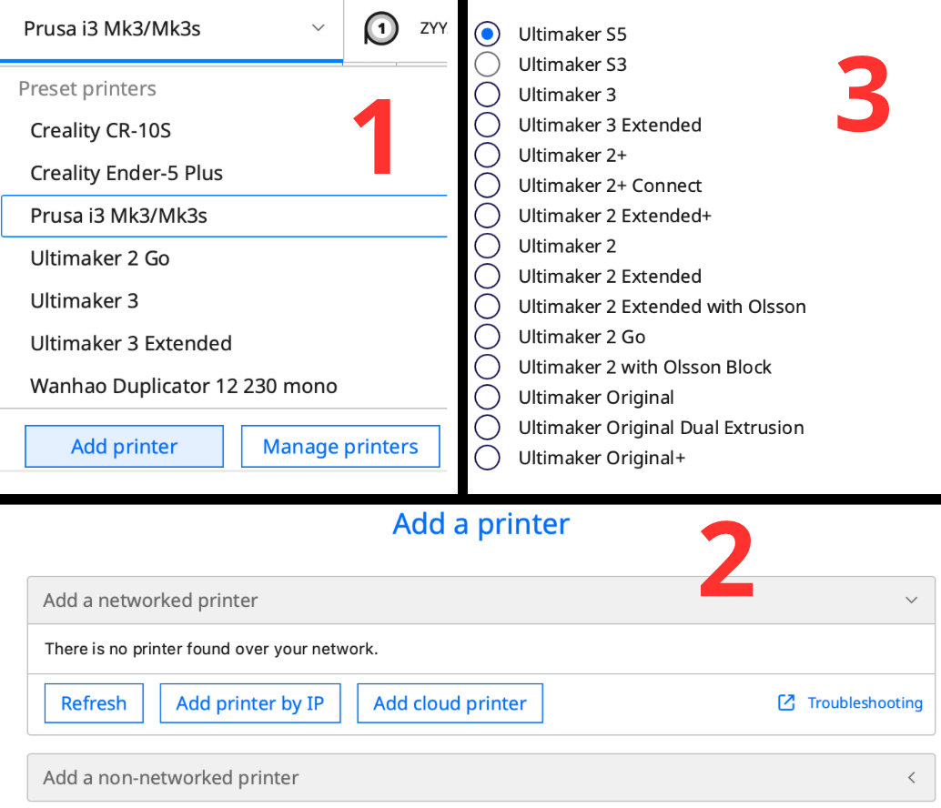
When we open our stl file with Cura, we can adjust a number of things. First of all, I had to add the Fablab's printers. Add printer, then Add a non-networked printer and then choose the printer you want from the list.
On the left is a bar with various options, used essentially to position our print on the printer, we can move it, rotate it, enlarge it... At the top you can also change the material you're using.
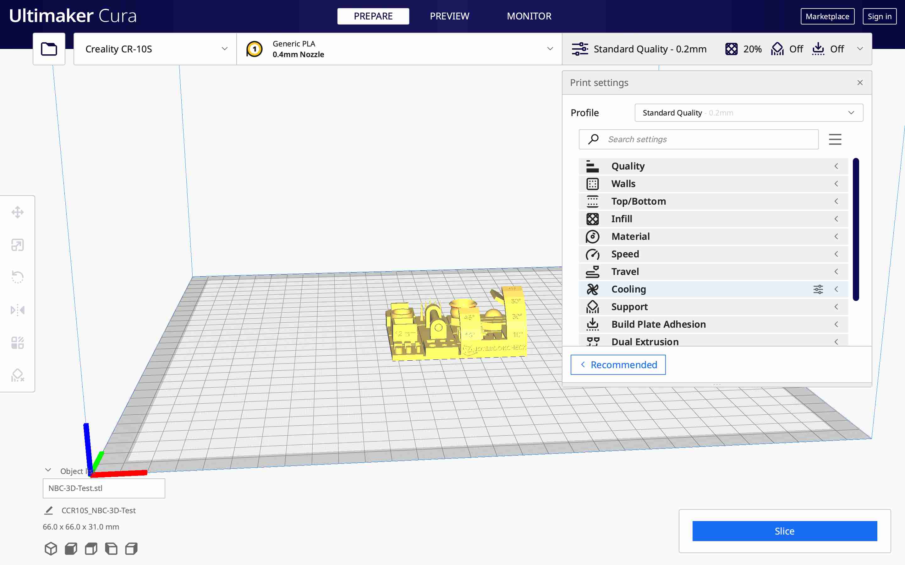
Finally, on the right are all the other parameters, as diverse and varied as they are. Some of the main ones are displayed in the top bar, such as layer thickness, fill percentage, the addition of supports and, finally, the presence of an adhesive plate.
In my case, I chose to leave all the Cura default settings for my file before slicing it. That is, a 20% fill with a cubic pattern, a print temperature of 200°C and a speed of 80mm/s.
Once these various parameters have been modified in our gise, we can slice our object and download it. My instructors told me that we had to be very careful at this stage because creality printers are quite demanding and we have to name our gcode with letters only, without any special characters or numbers to avoid any problems.
The file can then be placed on the printer for printing.
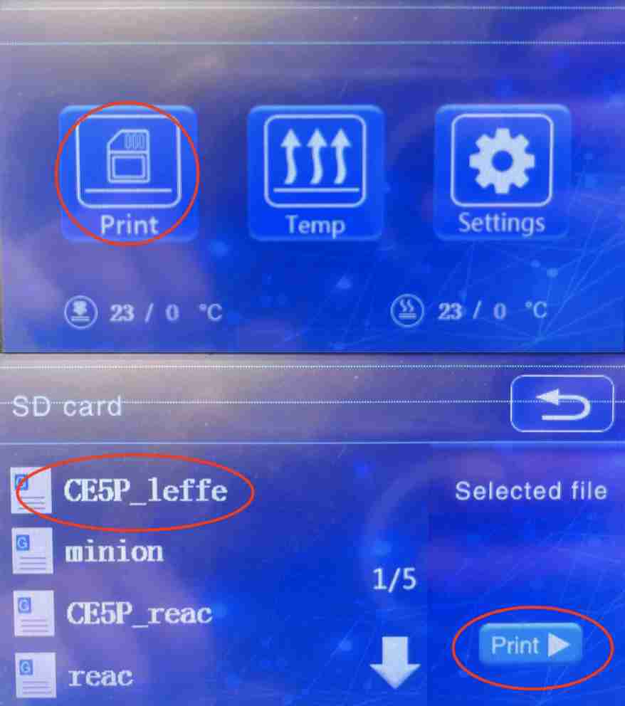
To start printing, simply go to the home menu, select print, choose your file and then click print. Printing will start when the tray and nozzle have reached temperature.
Unfortunately, my first test failed when I did the test, I used a spool that had already been used and the spool contained a knot that stopped the filament supply during printing.
Nicolas, one of our instructors, told me that I might have faults with my nozzle, which could be clogged, so I cleaned it with a needle.
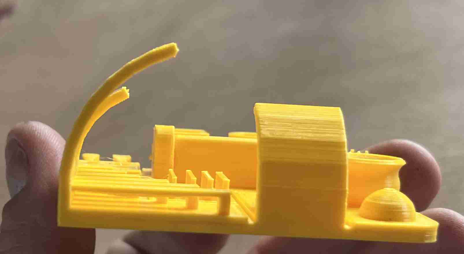
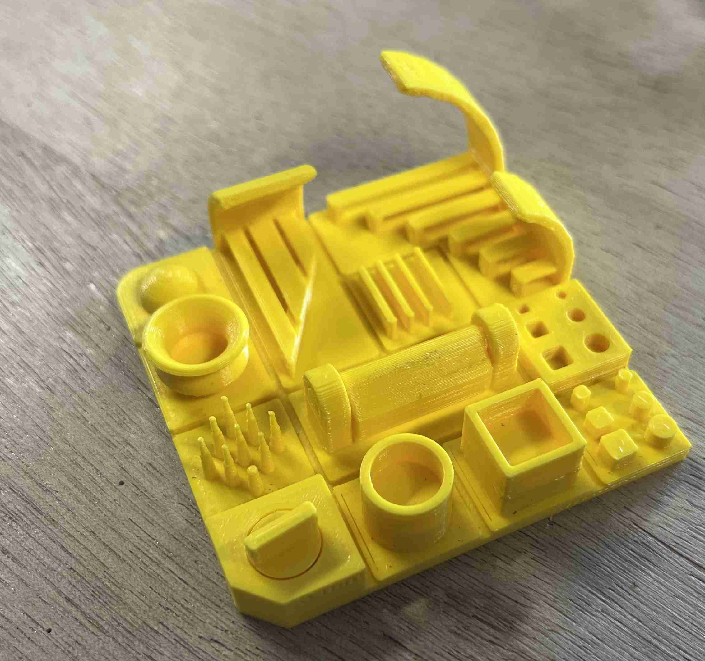
The second test was successfully completed and gave me an acceptable result, as you can see in the photo below.
Benchmark analysis
The Benchmark rendering is satisfactory, and in fact quite similar to that of the first, with the faults to be found in the same places. Of course, we can't compare everything because one is incomplete, but on the other hand, in the clearance test, for example, both produced very good results.
The main defects are in the 12mm cube, which has burrs on both designs. As far as the bridges are concerned, the filaments are lower from the very first ones, but the shape remains very correct right up to the last ones at 25mm apart. As far as the bends are concerned, we very quickly obtain a deformation of the original filament but this remains acceptable up to 50° and even at 75°, the result is very acceptable. The test on small objects was also satisfactory, apart from the tips which obviously ended up with a thickness of 0.4mm, the thickness of the nozzle. As far as measurements are concerned, I obtained a thickness of 11.9mm for the 12mm cube, which is quite satisfactory.
Even if this benchmark is not perfect, it is still very satisfactory.
Crality CR10 S5
In order to try another printer, I took the same design that I printed with the ender 5 Plus, for this I kept the same design as the previous one while making some modifications. I obviously changed the printer I was using to Cura, but I did make some changes, notably to the size of the nozzle mounted on the printer, which is currently 1mm. I knew that with such a large nozzle I'd inevitably get less satisfactory results but it's still worth a try.
The Creality CR10 S5 is the largest we have at Agrilab, with a printing area of 500x500x500, or half a cubic metre. It has a lot in common with the Ender 5 plus, such as its Cartesian coordinate system and bowden extruder. On the other hand, it also has some differences. For example, on this printer, the platen doesn't move vertically, it moves horizontally to make the Y shift.
Apart from changing the size of the nozzle, I applied the default settings that Cura applied, for example it set my default thickness to 0.35mm.
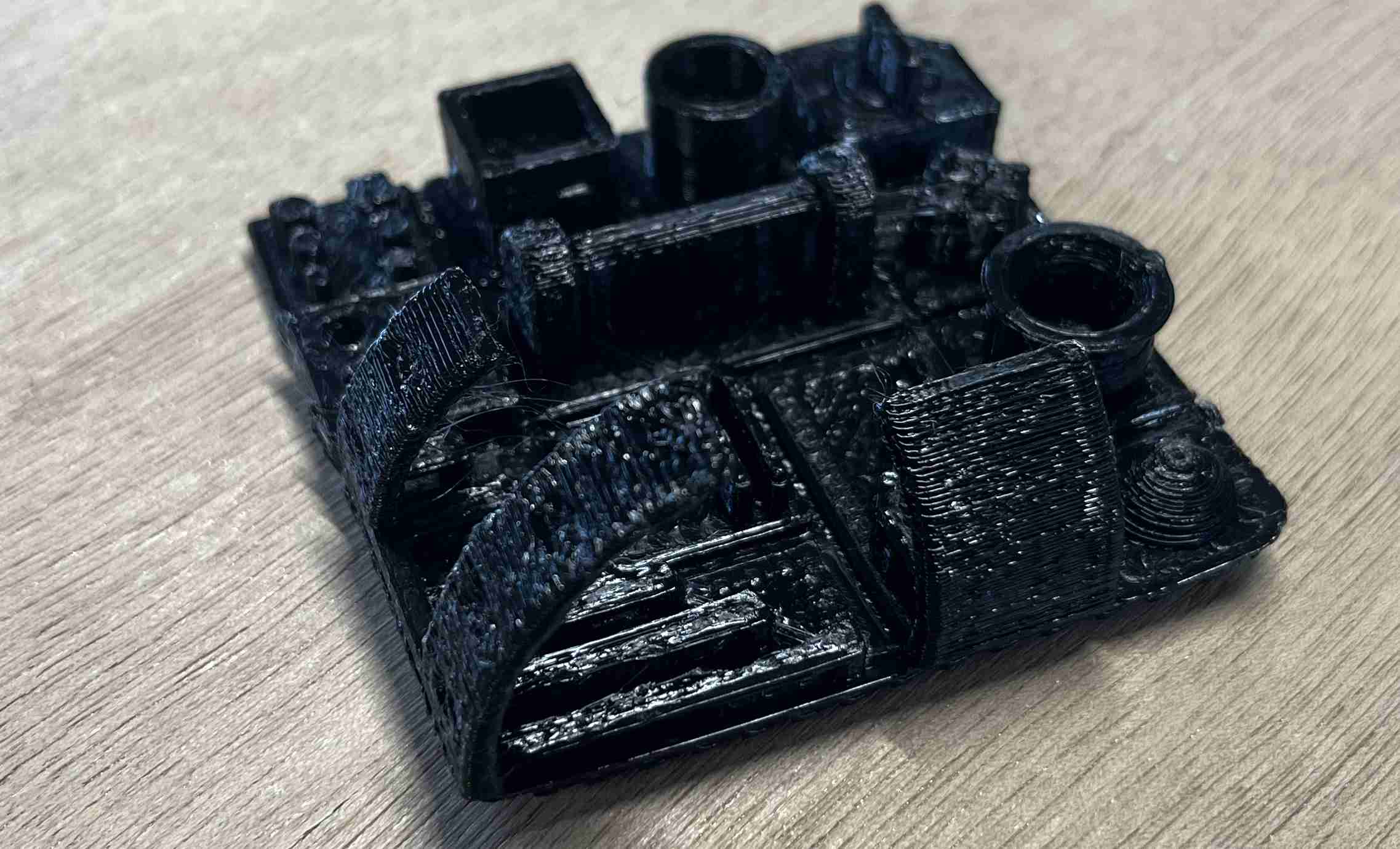
This first test was catastrophic, during the beginning of the iumpression, the machine stopped because it could no longer pull the filament, I looked and yet it was well free, when I tried to touch the machine, I touched the wheel which has surely changed the height because when I managed to restart it, it was very slightly lower than the layers before. Everything that was printed afterwards was no good, there were holes in the shapes, the layers were irregular... The result would have been less catastrophic with a smaller diameter nozzle.
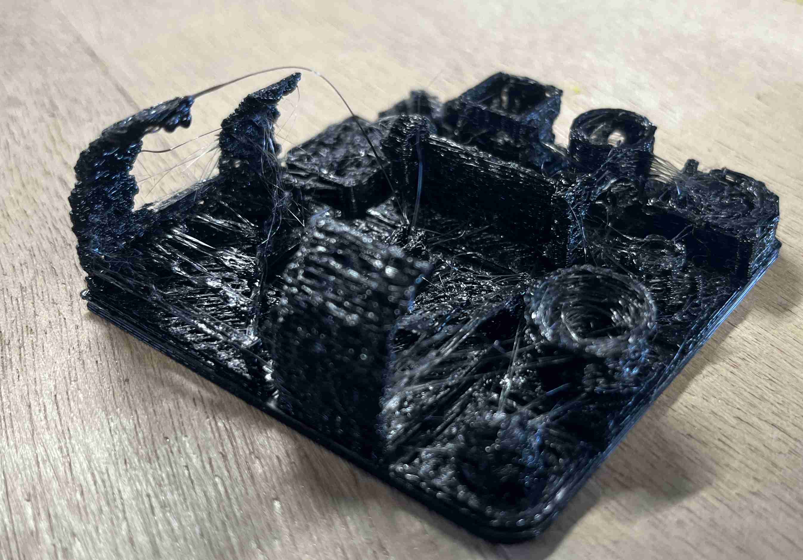
I tried to make a second one to get a better result and I succeeded. The result is acceptable for such a big nozzle, but not everything works, especially the two parts that test the clearance that are supposed to move and don't. I've tried to make a second one to get a better result.
I had a problem during printing, the cause of which I don't know. Unlike the first test, which adhered well to the tray, the second was printed too high, so the base was poorly attached to the tray and came loose when the plastic shrank. The result was an irregular shape.
To see the other tests carried out by other members of the group, you can visit our group page at of Agrilab
Individual assignements
Printing
In order to complete the exercise that we have to do this week, I would have liked to make some progress on my final project, but I didn't have anything to print that corresponded to the subject. I could have printed something like the box where my robot will be by simply adding a trap door with hinges created at once but I don't know what size the components will be, nor the number, besides, this object would probably have been very large and long to print, I could also have printed other components but these would have been too simple and could have been made using subtractive techniques.
So I thought of an object that has cavities and isn't very big. It's an assasin's teapot. If you're not familiar with it, it's a teapot that has two different containers. You can put a different liquid in each of the compartments and choose which one empties by blocking one of the air outlets. I find the concept quite special and amusing, so I decided to make a small one to fulfil my instructions.
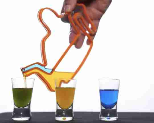
You can see from this image of this website the operating principle of the object
To do this I used fusion 360 again. I started by creating the body of the teapot, taking care to have two compartments so that the inside could be printed without any support. I could have used PVA, which is a plastic that dissolves in hot water, but my colleague Alexis tried using it and got very bad feedback, so I didn't want to expose myself to the same problem. Once I'd created the body of the object, I was able to add two holes in each compartment, one for the liquid outlet and the other for the air inlet. I added a spout and pipes for pouring as well as a handle.
Design
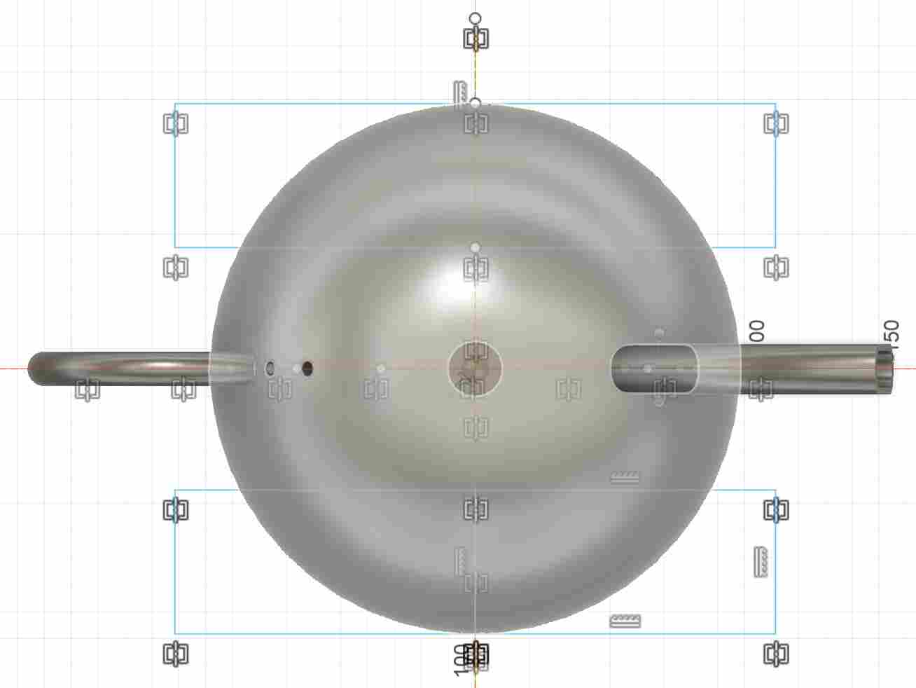
In order to design my teapot, I first made a sketch on a lateral plane where I drew the contours as well as the interior in order to create the two compartments. I wasn't rigorous enough in calculating the angles I applied to both the contours and the inside wall. I relied solely on my feeling of the Benchmark I'd made.
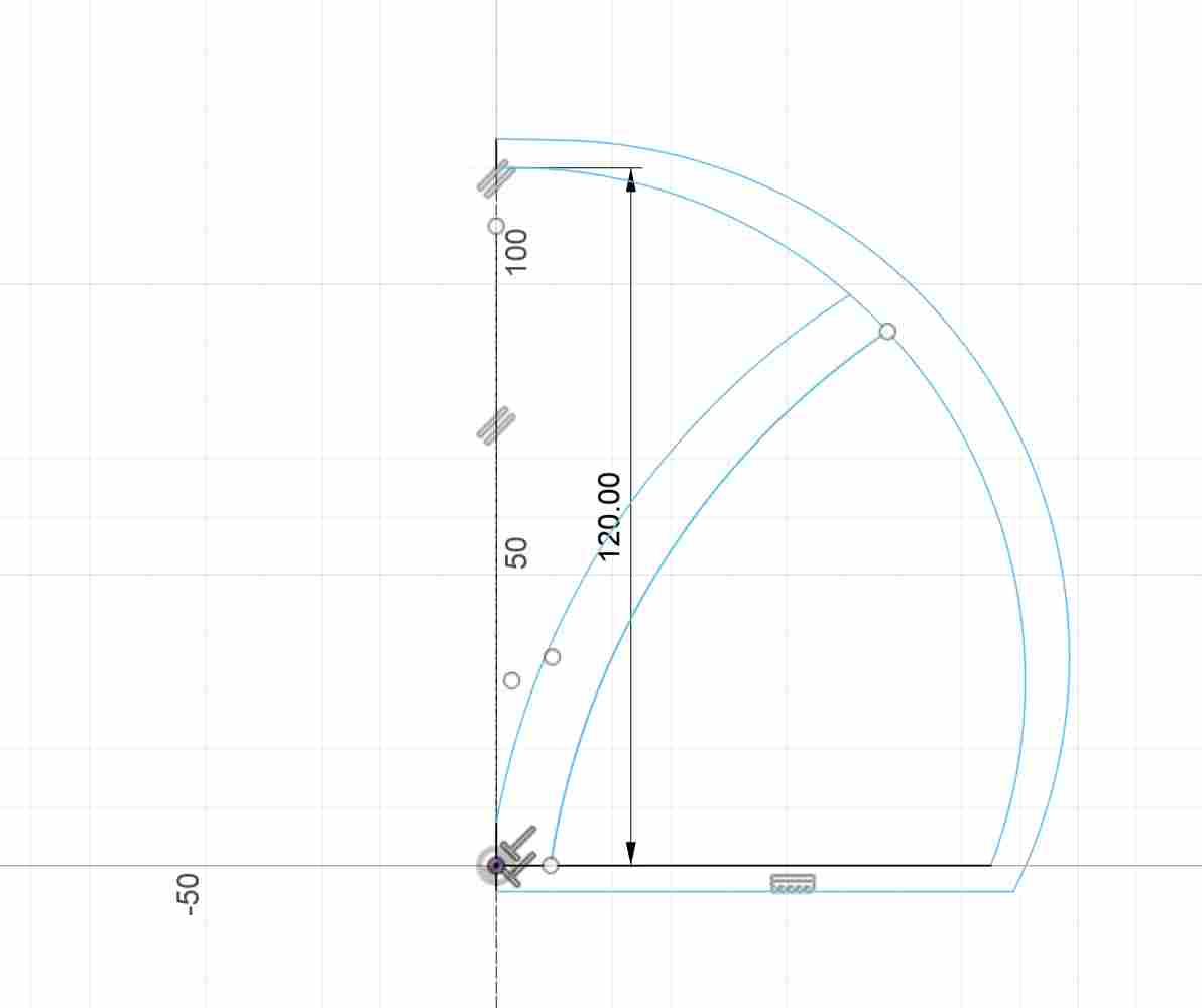
Once I'd finished my first sketch, I made a revolution to create the shape of the teapot. I then added some corner cut-outs to create the holes for the liquid to come out and for the air to circulate inside the teapot.
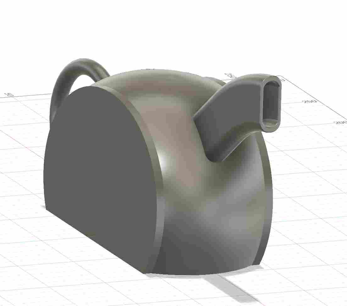
I then added the handle. I made a design error when I made it and put too much of an angle on the top, so the top of the handle printed out badly. To make the handle, I created a line with the shape I wanted and then used the tuyeau tool to create the body.
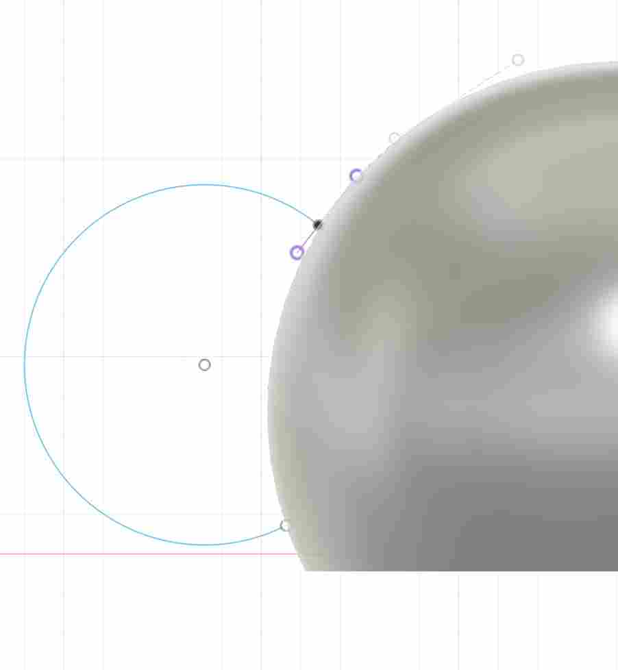
I then added the pipes to let the liquids out independently and the spout to hide them. Once the main components had been added, I created an extrusion on the sides to reduce the size of the teapot, saving both volume and printing time.
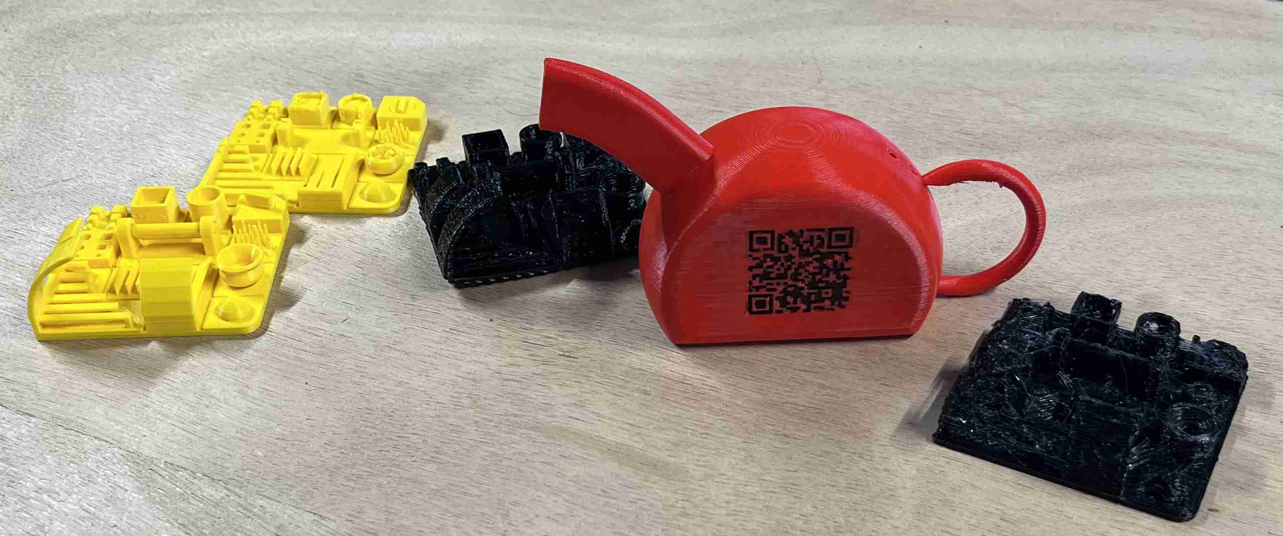
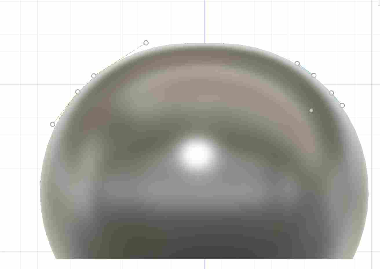
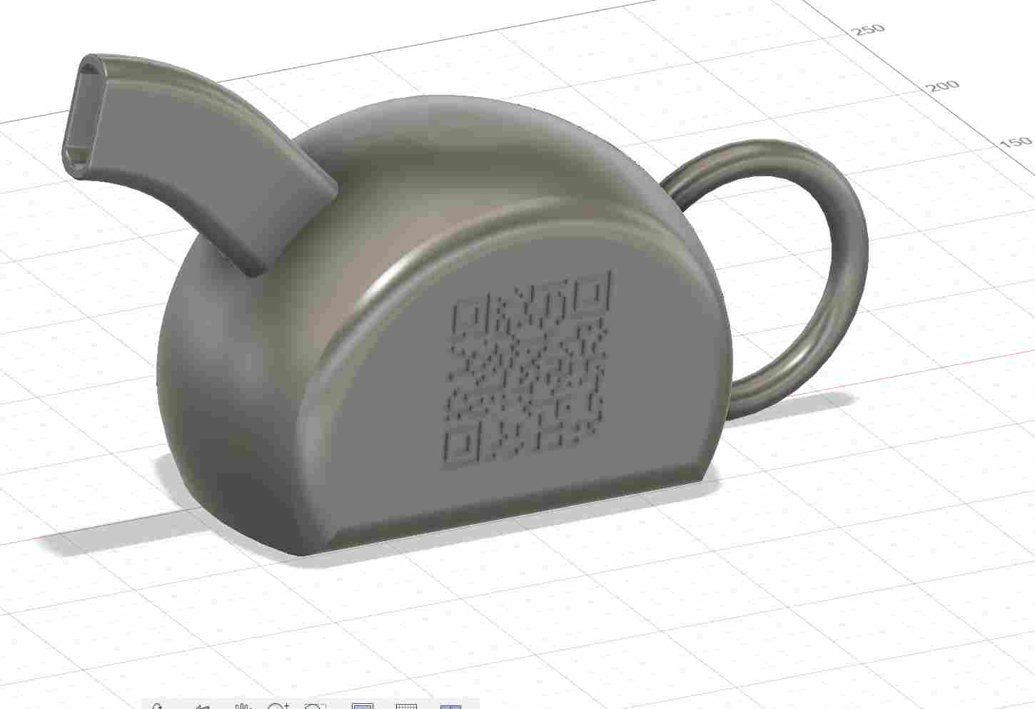
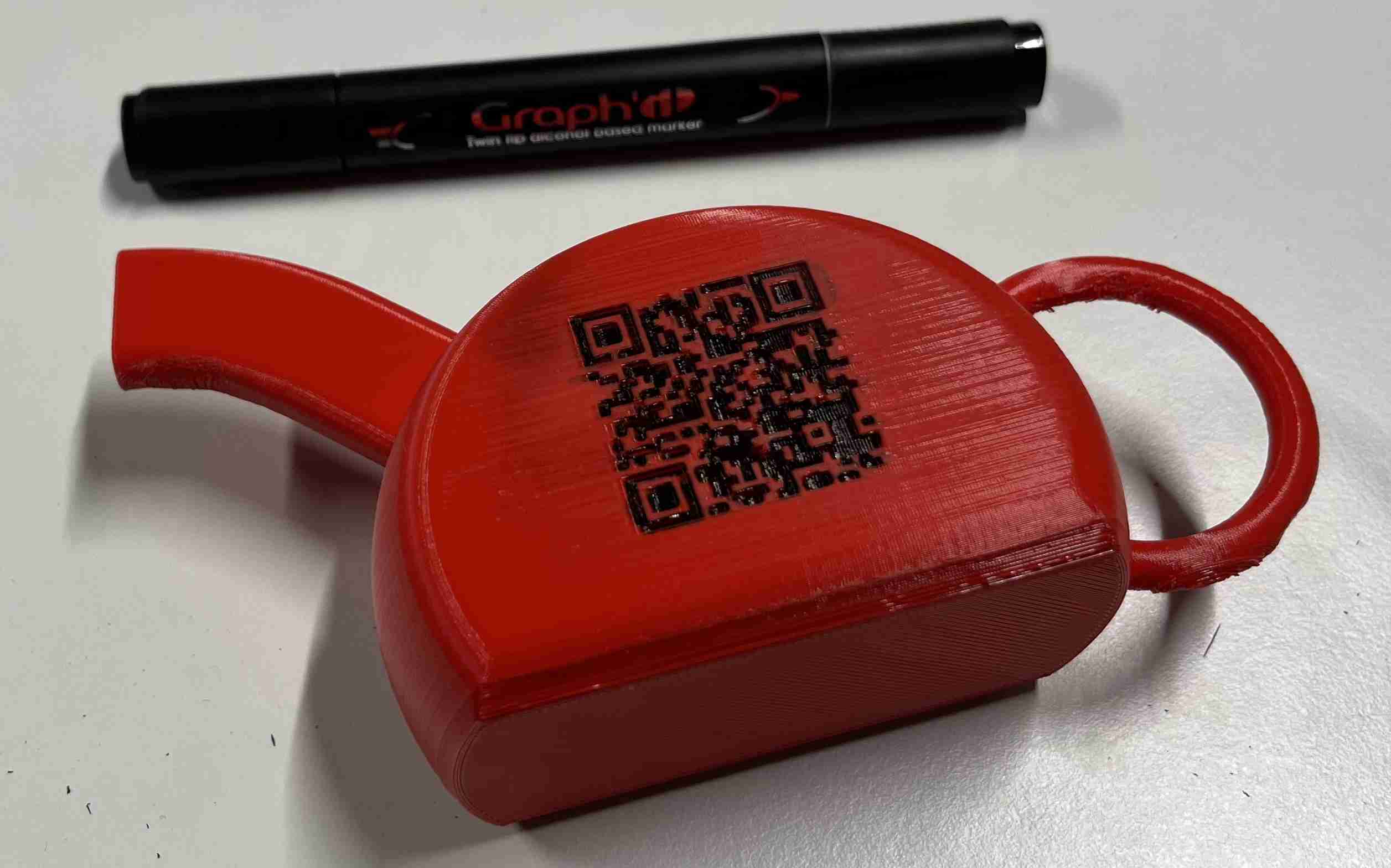
Finally I added the fillets and extruded the QR code to achieve the following final result:
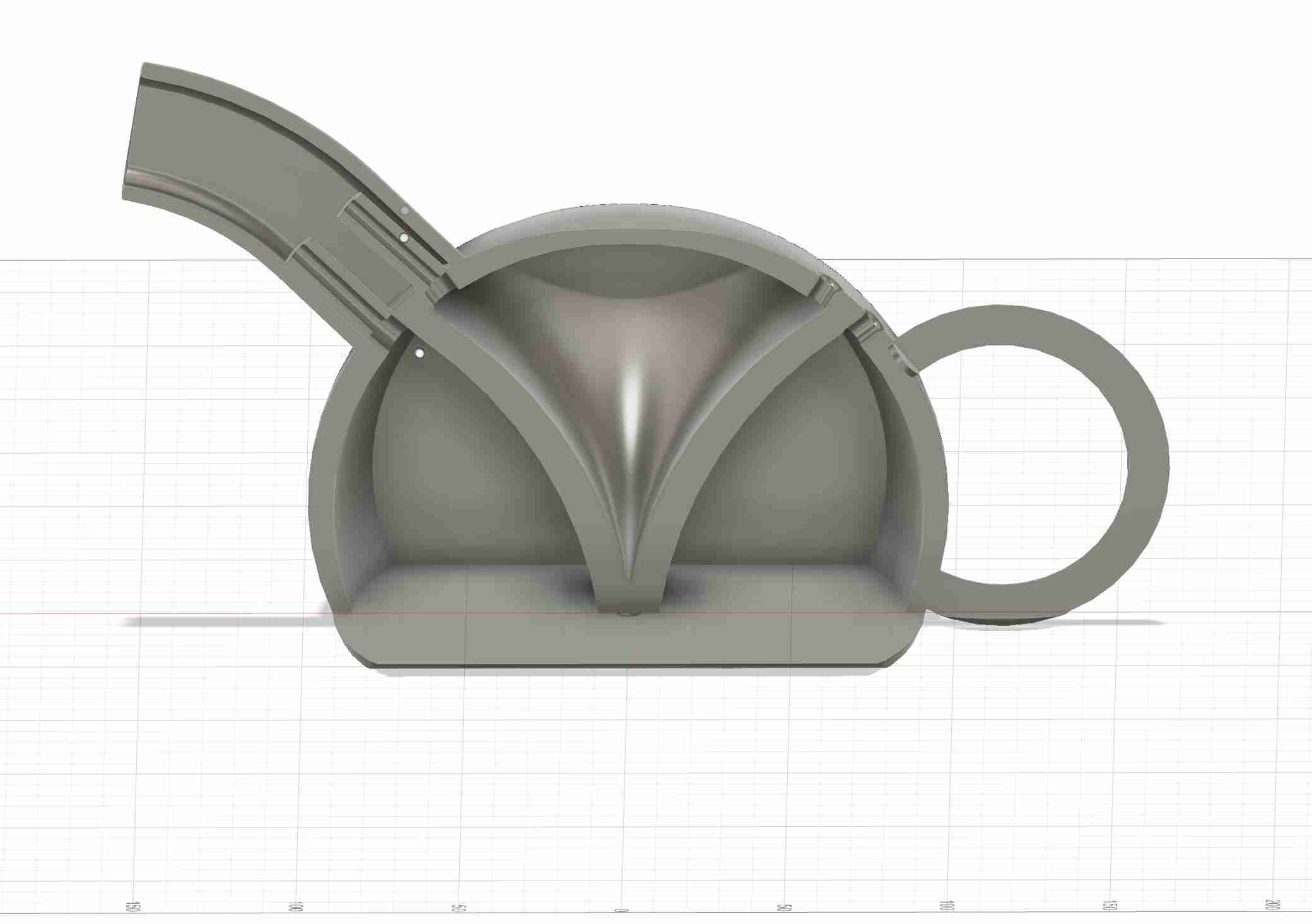
This cross-section will probably give you a better idea of how the teapot works and how I imagined it.
On Cura, I resized the teapot so that it was smaller and therefore consumed less PLA and printing time. I've also only put supports on the tray, so that I don't have any on the inside of my teapot.
QR Code
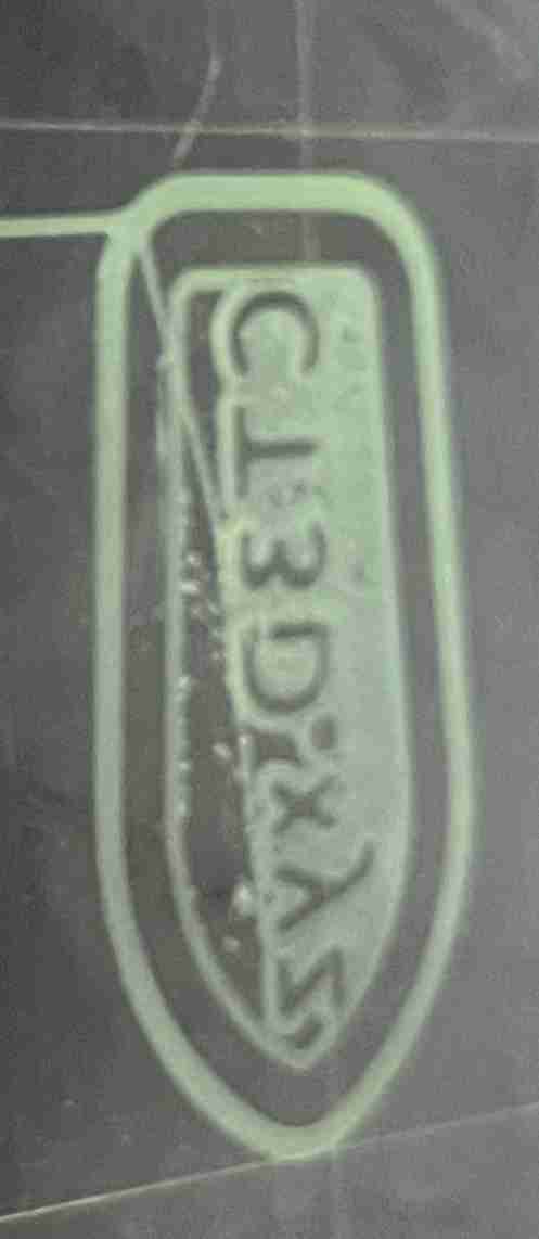
At the start of the week, our instructor showed us a whole host of objects that had been made at Agrilab. However, we have benchmarks in front of us but we don't know what their documentation was, where the files came from, on what machine, with what PLA? So I decided to add a QR code on my teapot, linking to my documentation for the week, and I'll try to integrate it into the other objects later (benchmark, etc.). To create it, I simply went to the website ME QR, simply click on URL/Relier and add our link. You can then personalise and download the QR code in png or svg format.
I then used the insert svg function and extruded it to make it stand out. The print result is quite satisfactory and clearly visible, but I can't manage to flash it with my phone.
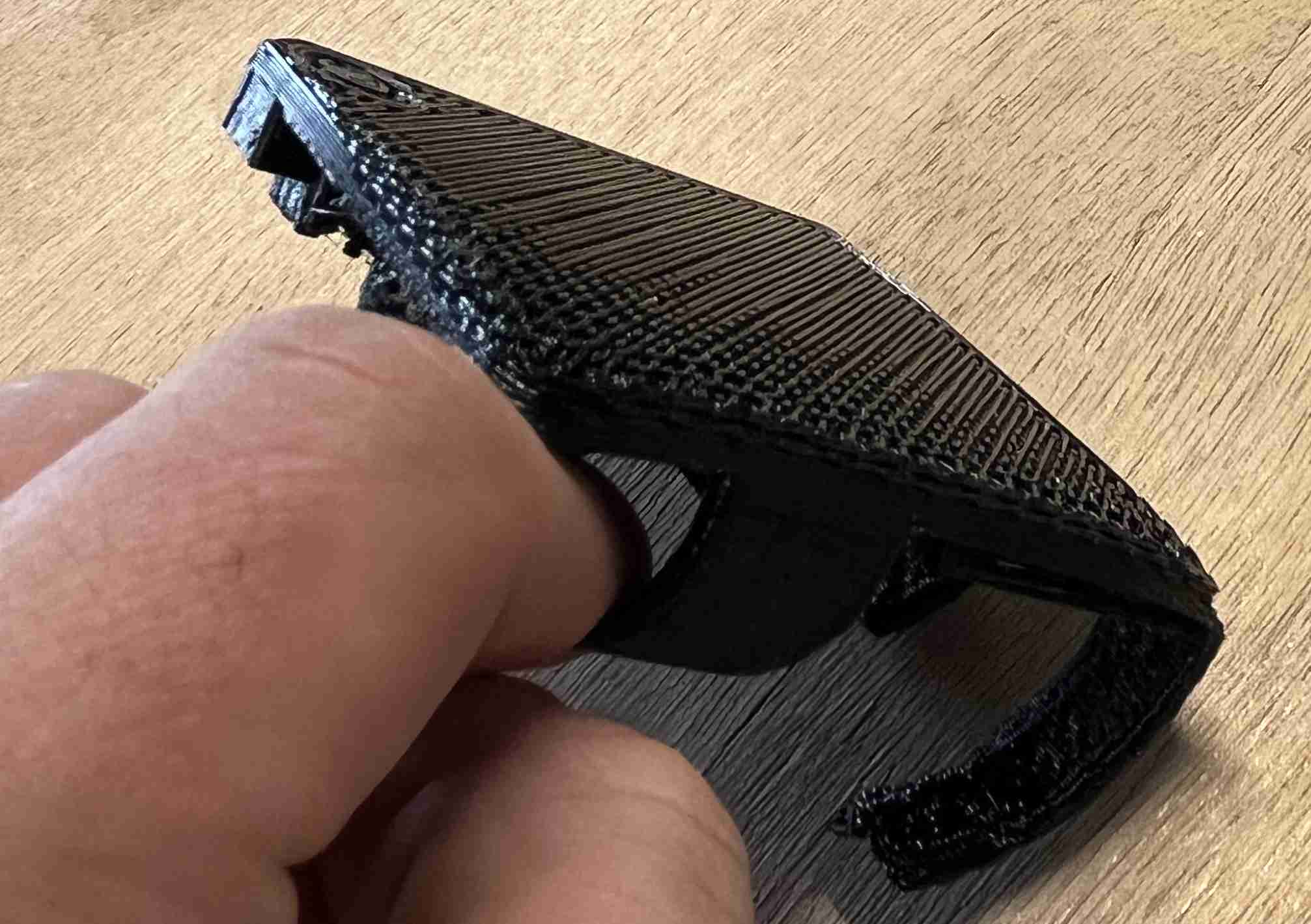
Overall, I'm very pleased with the result, the whole thing is well done, the QRcode is visible, the walls are uniform and homogeneous, the beak despite the angle is very satisfactory, the only flaw I can see was predictable and that's the handle which printed very badly, the angle I gave it was too large for it to be satisfactory. I'm satisfied though, the arc of the circle still managed to join the two pieces.
After that, I tried putting marker on the QR code and then cleaning it up by sanding and putting alcohol on it, so you could see the QR code very clearly, but with my phone I couldn't scan it at the time. Once everything had dried, I managed to scan it but it took a long time and didn't work very well. I probably should have set the resolution lower so that the squares would be bigger and easier to scan.
Test
After de-supportising and removing the various failed filaments from the bail, I can finally move on to the functional test.
This test was very satisfactory. You can see that when I plug one or other of the holes, it's the liquid from the reverse chamber that comes out. When I plugged both holes, both liquids came out.
If you ever want to reproduce it, you can find the 360° fusion file. here and the F3d filde here.
Other tests
Another thing I wanted to try out this week was printing flexible filaments, i.e. TPU (Thermoplastic polyurethane). I'd never tried it before because it requires a direct drive extruder, unlike the other bowden printers I've used. In order to get advice on printing this material, I used the following resources this videoIt gives a lot of advice, for example to dry the filament a long time before printing as it absorbs a lot of moisture, this was a sample and so wasn't kept in a dry, airtight environment. At first I tried this without taking it into account, but my nozzle clogged up very quickly, and I had also forgotten to indicate that the filament was TPU on cura. The object I originally wanted to print is this Benchy that I found on cults 3d.
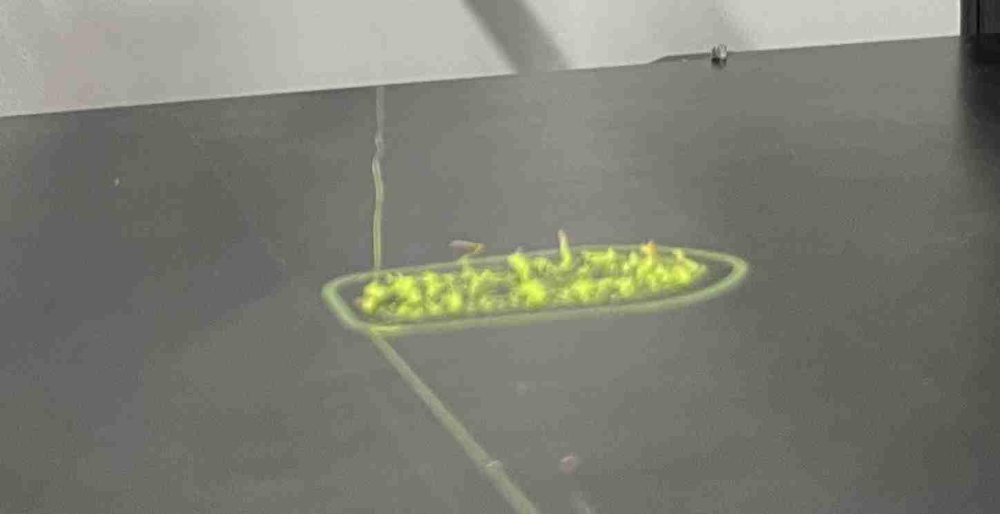
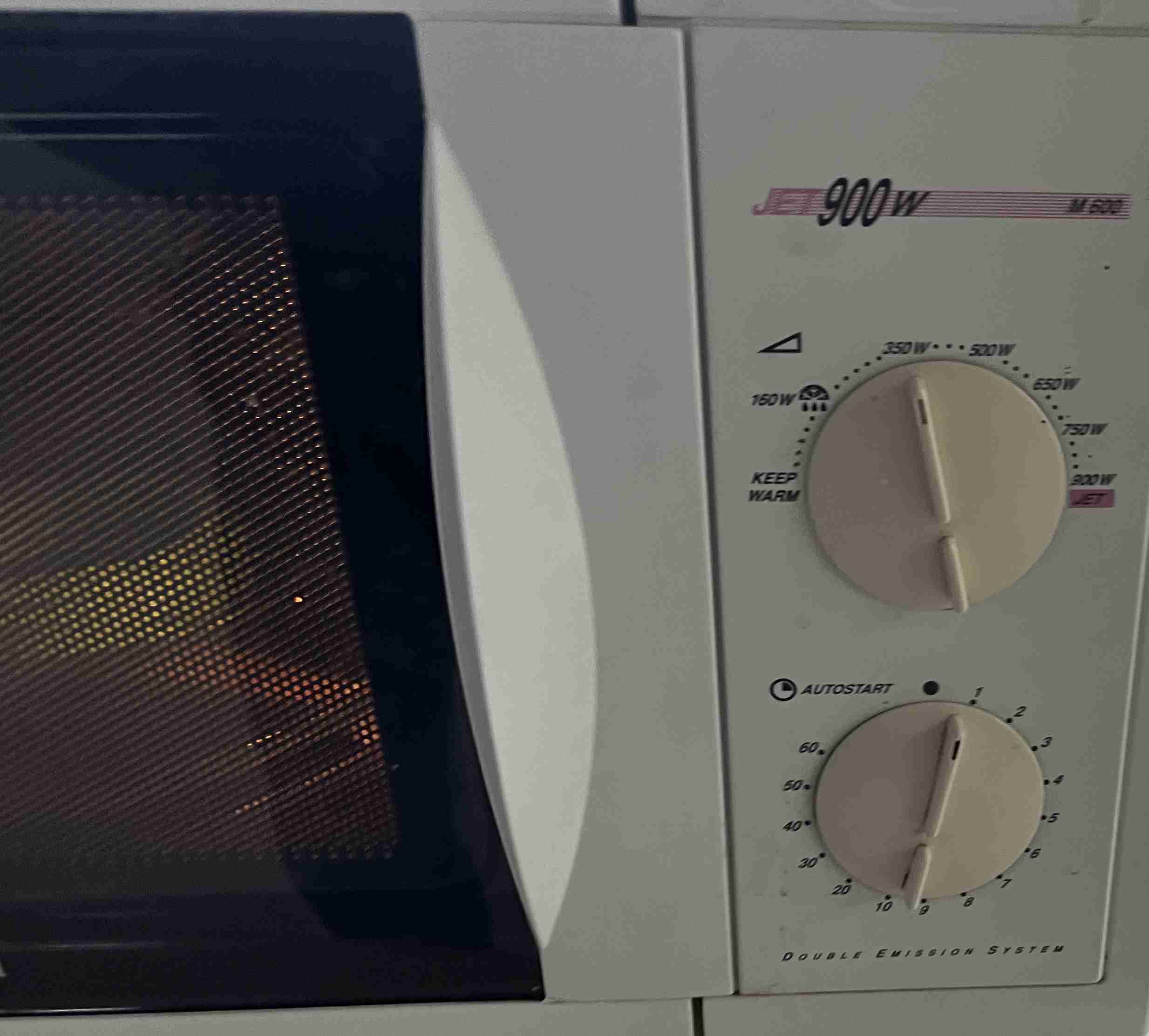
I then tried again by putting my TPU in the microwave at 350w for one minute before using it again and making the necessary adjustments.
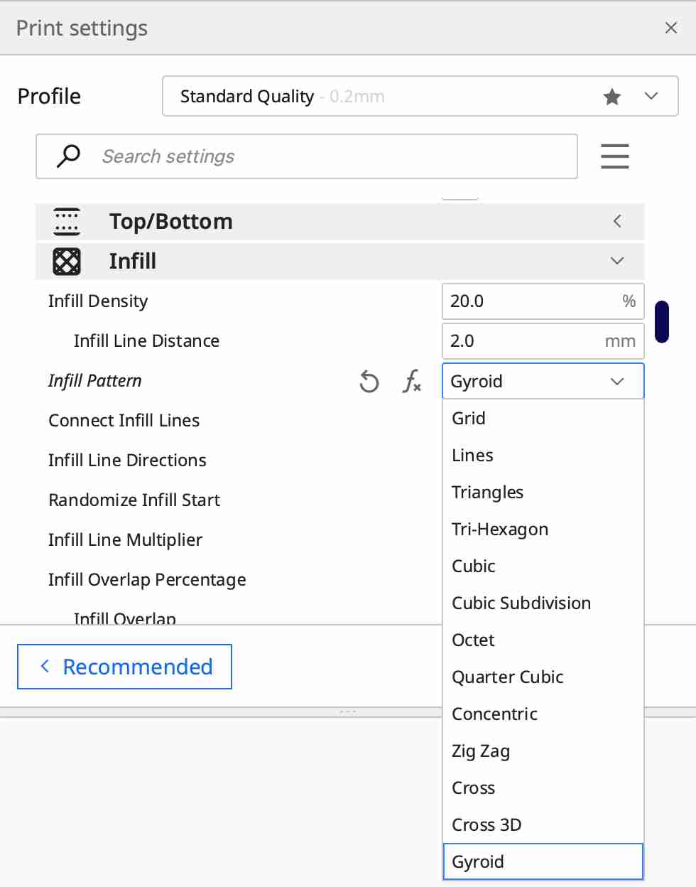
The ideal shape for using this material is the giroid, which is best suited to printing with this filament and offers the best rendering. It is also advisable to remove the shrink wrap because of the high flexibility of this material.
After changing all these settings, I tried again and it was again a failure, the nozzle clogged again obviously stopping the printing. So I gave up printing TPU, I suppose that to get satisfactory results it's important to have a new reel or one that has been kept in excellent condition.
Scanner test
To carry out the scan, we have two different devices, a kinect 1 originally developed by Microsoft to play with the Xbox 360, it can also be used for 3D scanning. We also have an Einscan pro shining 3d scanner with industrial pack and a kinect, which is a real 3D scanner with a removable tray.
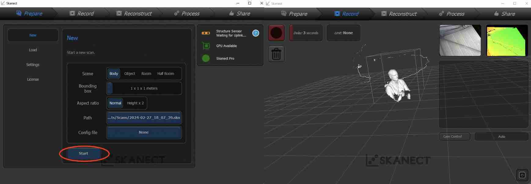
We made our three scans during a workshop where we were learning how to use them. We scanned different objects, first a fork, then an ammonite and finally we scanned Alexis and myself. Pol-Emile scanned the ammonite using the Einscan, and you can find out more about this device on his page. Alexis and I carried out our scans using the Kinect and the Skanect software. We didn't have to download the software as it was already installed on the school computer, but I did find this documentation from Fabalabo, which explains how to download and use Skanect. To use the kinect on a computer, you'll need a dedicated power supply. Originally, the kinect was used on the XBOX 360, but if you want to use it on a computer, you'll need a power supply of the same type as the XBOX 360. this oneYou can then open the Skanect software and go to the menu prepare, Here you can choose the mode of your scan and various parameters, or open an old one. When you want to start the scan, simply click on start. This will take you to the record, It's at this stage that you need to scan the object or the person, in my case Alexis. You need to take your time and not make any sudden movements, because you could lose the scan and start again from scratch, or you could end up with results of less than satisfactory quality.
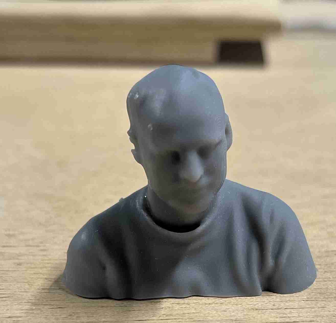
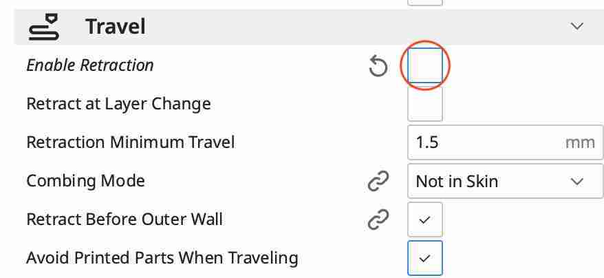
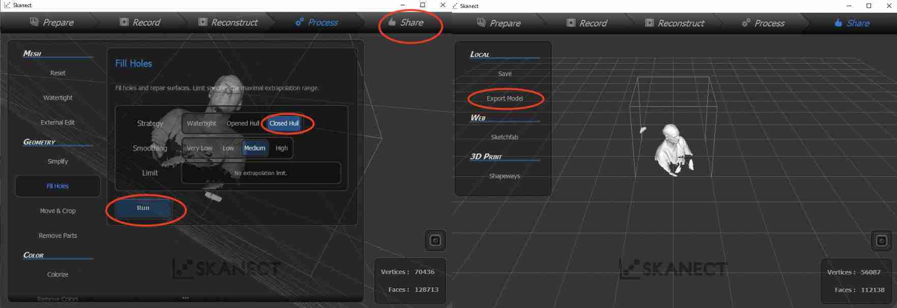
Once the scan is complete, you can go to the Reconstruct, I personally didn't spend much time on this stage during my scan. We can then move on to Process function, which allows you to pick up elements that don't fit on your scan, I used the Closed Hull in order to fill in the holes in my scan, particularly around the chin, because I hadn't bent down enough when scanning. Once you've clicked on run, the software will apply the changes. If you're happy with your model, you can go to the shareand export it, in my case I exported it in svg format.
Once these various stages have been completed, we get our scan, which is more or less regular depending on the area, as shown below.

You can find the fusion link here, and the f3d file here.
Impression du scan
To take things a step further, and also because I hadn't yet worked with the resin printer, I decided to print my scan of Alexis on the SLA printer. To do this, I had to go back to my scan using fusion 360. Once I was in the software, I used the mesh menu, which includes a large number of options for transferring stl files, for example, as in my case. First of all, I used the modify then separate tool. So that I could delete the various scattered elements and keep only what interested me.
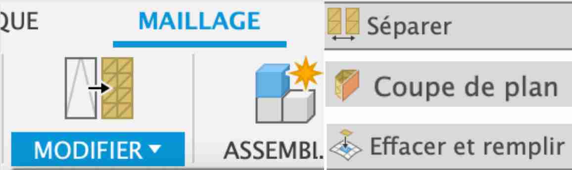
I then used the cut plan tool to keep only the part of Alexis's bust that is complete and well done. Finally I used the fill tool to fill the huge hole created by the cut to 100%. All I have to do now is export it in stl format for printing.
SLA
The acronym SLA stands for stereolithography, a process in which a laser is precisely applied to the resin to polymerise it. At Agrilab, we have an SLA printer. Formlabs, Form 2.
In order to print with it, I don't use the Cura slicer as with filament printers. The formlabs printers have their own slicer named Preform. To use it, simply open the software and import the stl file you prepared earlier. Once the file has been imported into the software, you can use the magic tool to orientate your model in the best possible way for resin printing. Unlike filament deposition, we're not going to melt a solid and then cool it down, but we're going to polymerise a liquid resin into a solid state, so our liquid material needs to have a constant flow to maintain its quality. This is why SLA printing is not done flat as it would be logical to do.
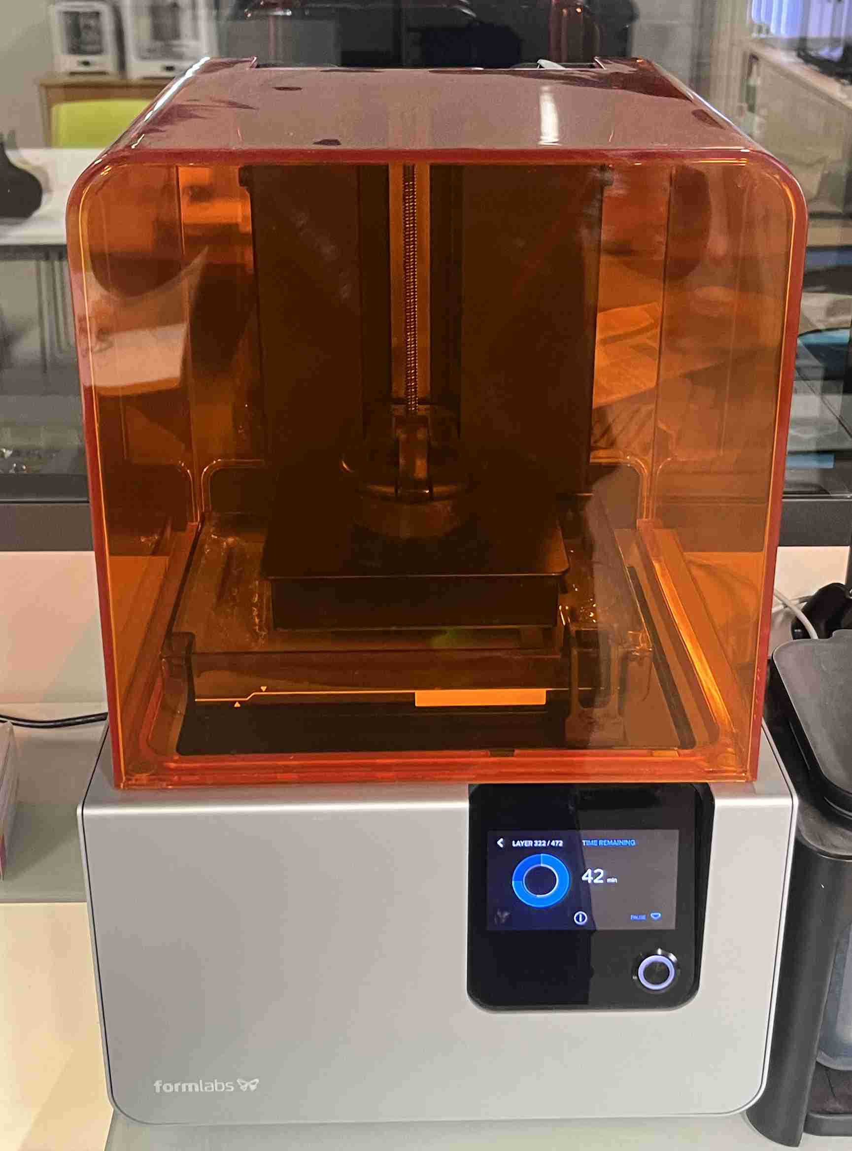
I made this print using grey V4 resin from Formlab, developed directly by the manufacturer. This resin is inserted into the printer in the form of a cartridge, so all you have to do to load it is change the cartridge. To start printing, all you have to do is connect the computer to the printer via USB and press Send folder to printer. The file will be loaded onto the printer very quickly. You then need to go to the printer and press the main button to start printing. If you haven't yet opened the reservoir to allow air to enter the cartridge, the resin won't come out - it's the same way my teapot works. Once you've finished printing, just open the printer and remove the tray. There's a support supplied with the machine that allows you to position the tray at 180° to the printing direction. Make sure you wear gloves for the following steps if you don't want any resin on your hands. You can use a spatula to remove the print and paper to clean the tray.
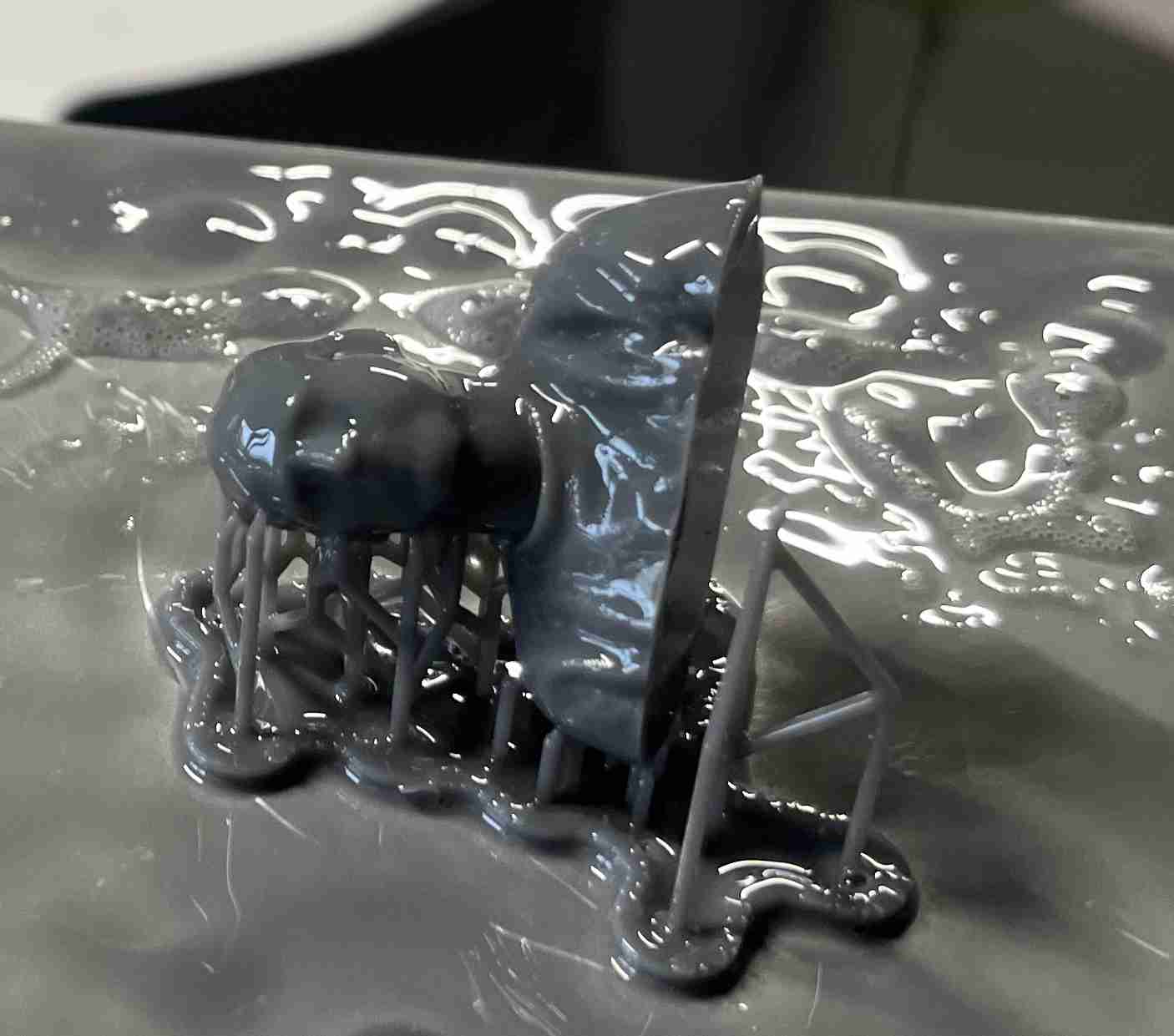
Post processing
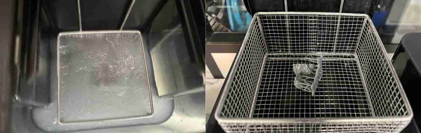
Once the print has been removed, it can be immersed in IPO (Isopropyl alcohol), which will clean and sterilise the resin. According to the resin documentation provided by formlab, it should be left to clean for 10 minutes to sterilise all the resin. To clean the resin, we have a Formlabs wash, which will clean the print by agitating to clean as much of the part as possible.
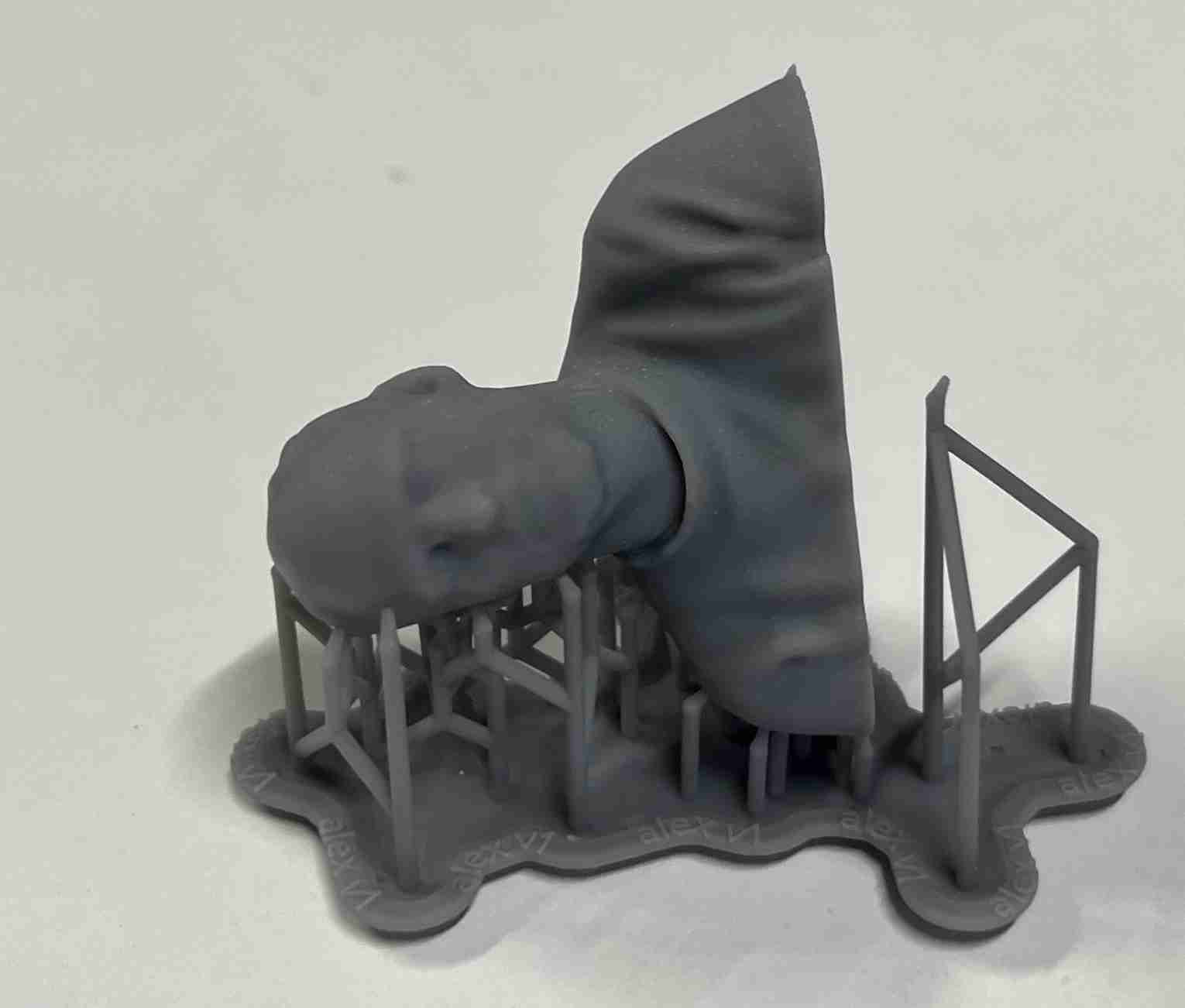
Once our cleaning is complete, we need to dry our print using UV rays. To do this, Agrilab has a Formlab Cure, a UV booth dedicated exclusively to this purpose. According to the resin's documentation, it is recommended to dry it at 60°C in a UV booth for 30 minutes. You can gain slightly by leaving it for an hour, which is what I did.
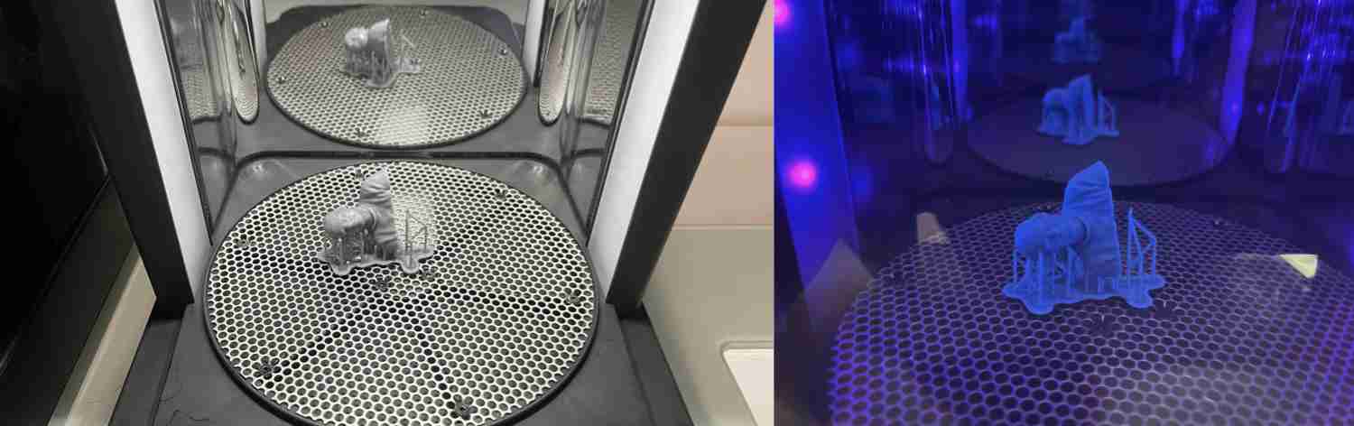
Our part is almost finished at the end of this last treatment, all that's left is to remove the supports, which I did by hand and which went rather well, but at the end of this stage, you can still see the marks where the supports were positioned. Here's the result of the final part once the supports had been extracted: