Week4. Embedded programming
Hero shoot
Assignements
Group assignements
-Characterize the design rules for your in-house PCB production process
-Send a PCB out to a board house
Individual assignements
-Make and test a microcontroller development board
-Extra credit: personalize the board
-extra credit: make it with another process
Group assignments
For our group work, we started with a workshop where we learned all about the machine and its operating principles, and all the steps we had to take to go from our initial png file to our printed circuit board. We carried out an initial test together with our instructor, which proved to be satisfactory. We used a Sorotec L2SA 0.4mm milling cutter.
To find out how the machine worked, the three of us chose to try out a different cutter. Alexis tried the L2SA 0.4mm, Pol-Emile tested a V-bit and I tried an L1S 0.4 SL2.0.
Test L1S 0.4 SL2.0
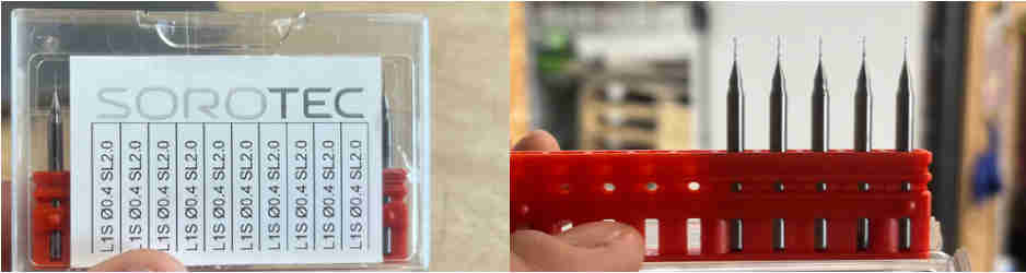
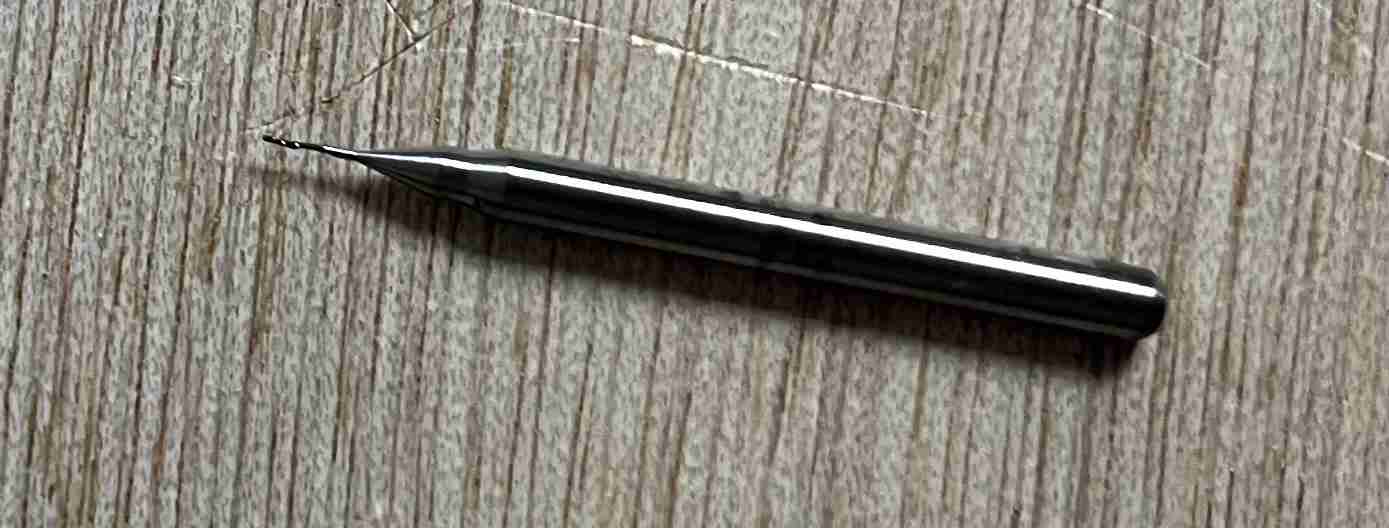
So I was interested in using L1S 0.4 SL2.0 milling cutters, which have the particularity of being single flute, with a diameter of 0.4mm and a length of 2mm. I'm guessing that this model is no longer available because when I went to the website Sorotec, I couldn't find the model I was using and therefore the technical data sheet. When I first tried it out, I thought it would break during the test because it was so thin and long. I made the traces with this file and chose to use only 1mm/s as the speed parameter to avoid potential breakage. For the other parameters, I used the same values as with the L2SA 0.4mm. For cutting, I used a 1mm L2SA cutter as for the other tests, with the same parameters.
You can find the rml files for traces and outline here.
Contrary to what I thought, the milling cutter didn't break and on the contrary it gave a very satisfactory result. I chose to use it to make my PCB but it broke during the milling process.
You can find all the information regarding our tests on the Agrilab page of our week
Ordering a PCB
In order to order a PCB, we first looked at which PCBs we could try to make. After a long period of reflection, we found a trio of boards made a few years earlier by fabacademy instructors.
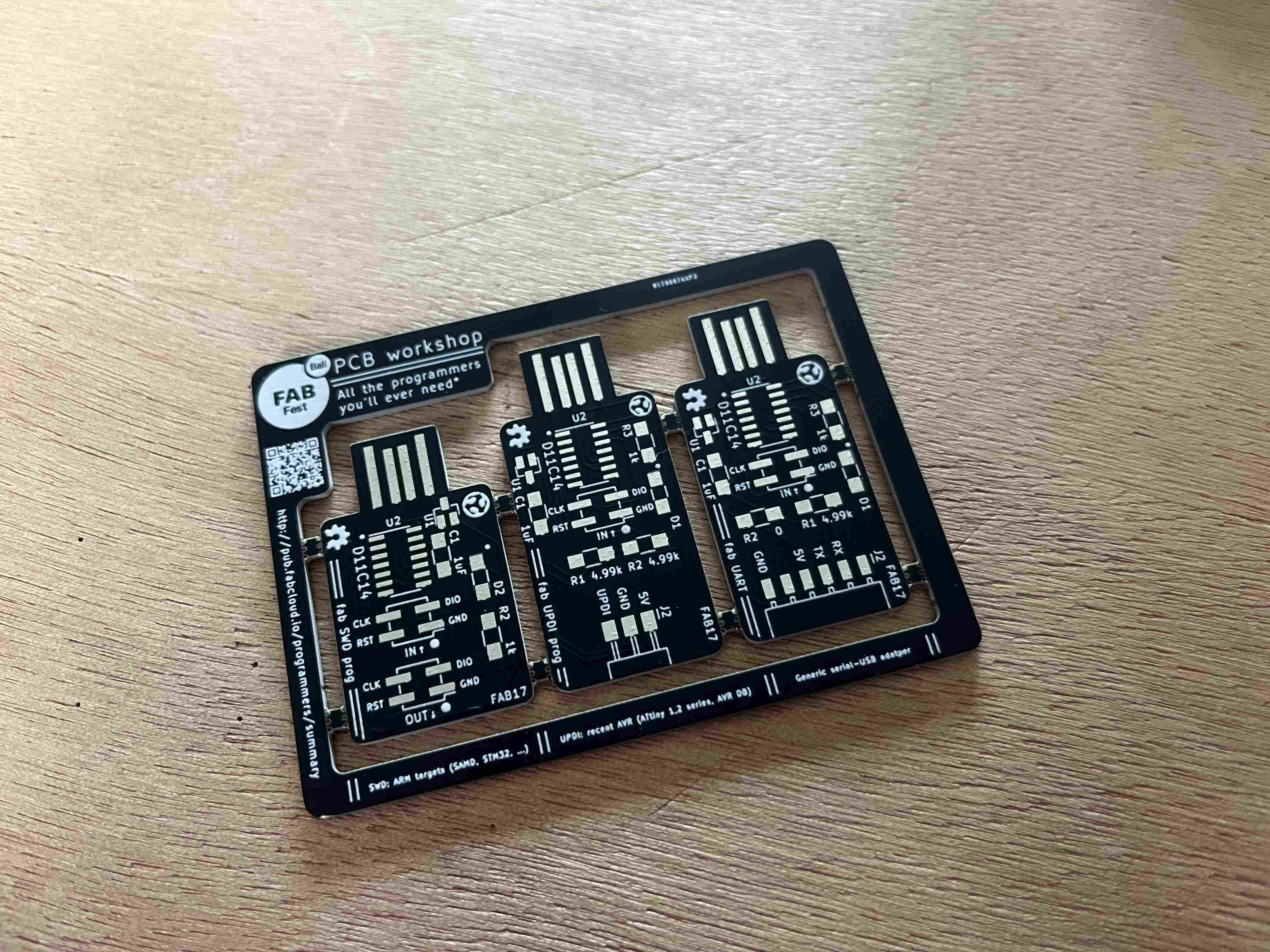
In the end, we were helped by Henk Buursen, a fabacademy instructor in Amsterdam who had been involved in the creation of these boards. Henk was able to direct us to this documentation of the Programmer Serial D11C. This board is a UART programmer for programming 5V BOARDs. We were thus able to download the Gerber file, which you can download here. here.
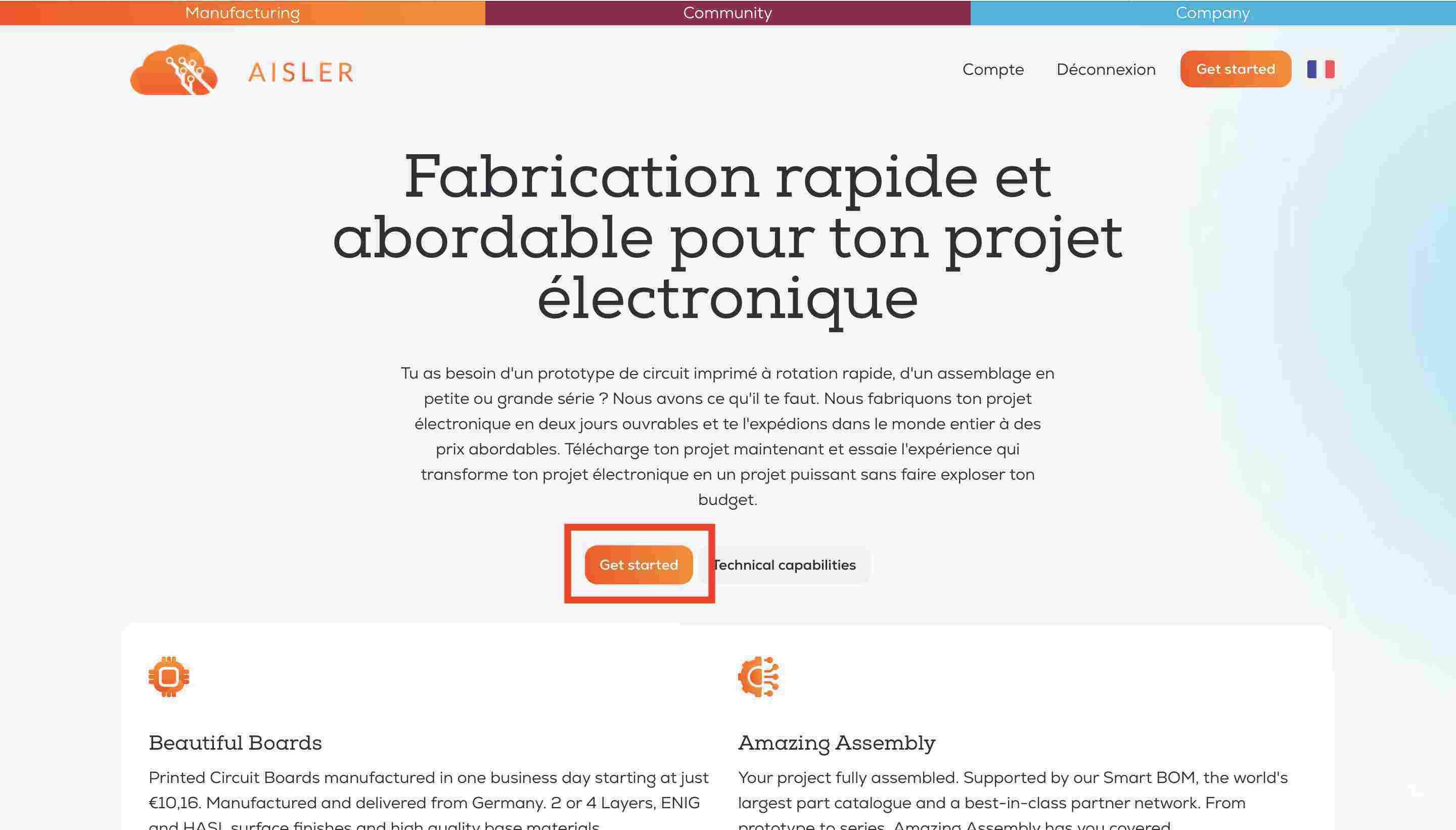
We then had to send the PCB to a manufacturer, and with Luc's advice we chose to work with Aisler a German manufacturer. All we had to do was follow the steps methodically, the site is easily accessible and fairly simple to navigate. First, we'll go to the home page and select getting started
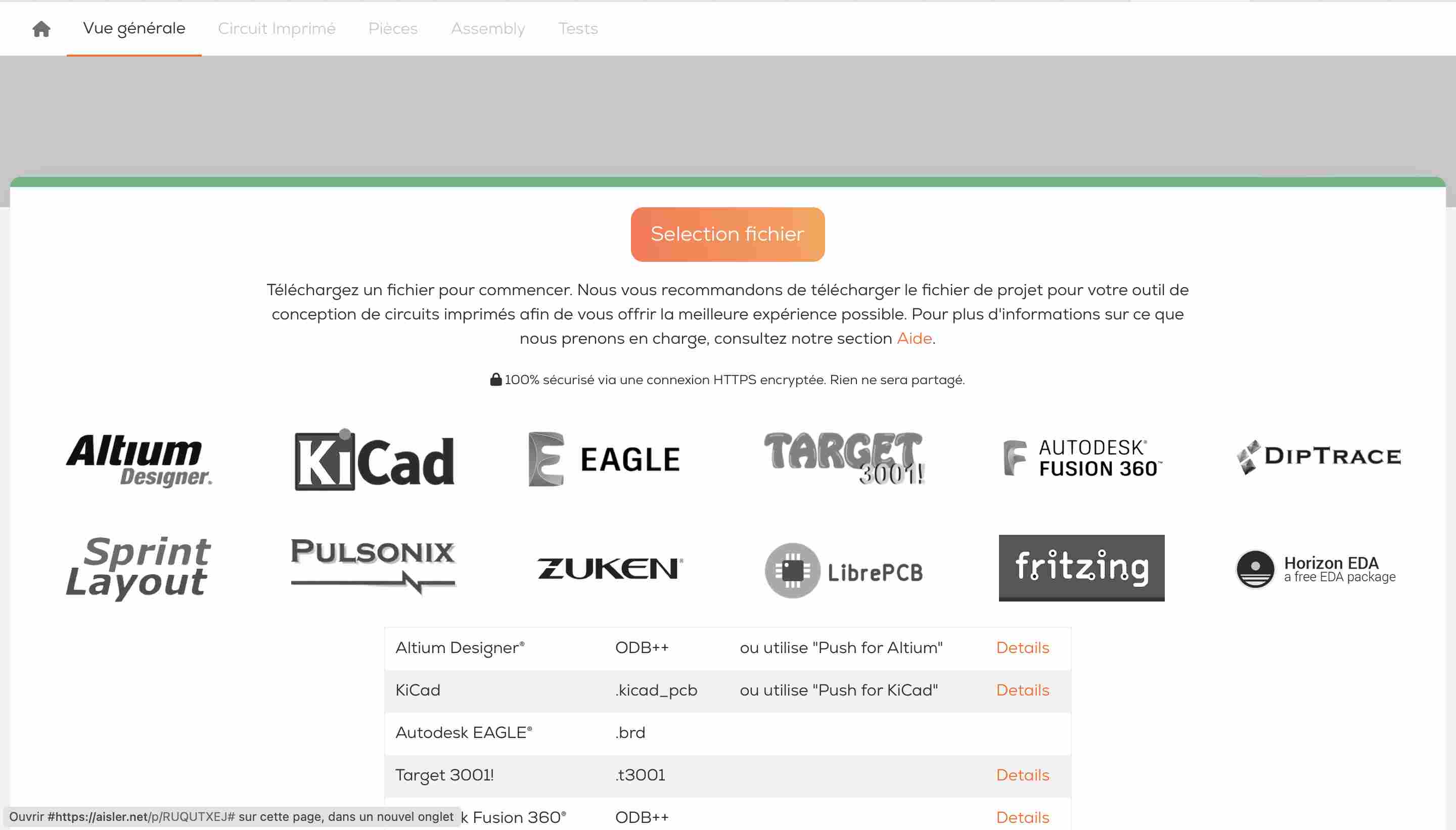
We then arrive on a page where we can select our file. There are different methods, for example using a Kicad plug-in to send the information directly from our PCB. .zip
We can then choose (if the result is satisfactory) different parameters for our board. In our case, we've chosen the most classic parameters there are.
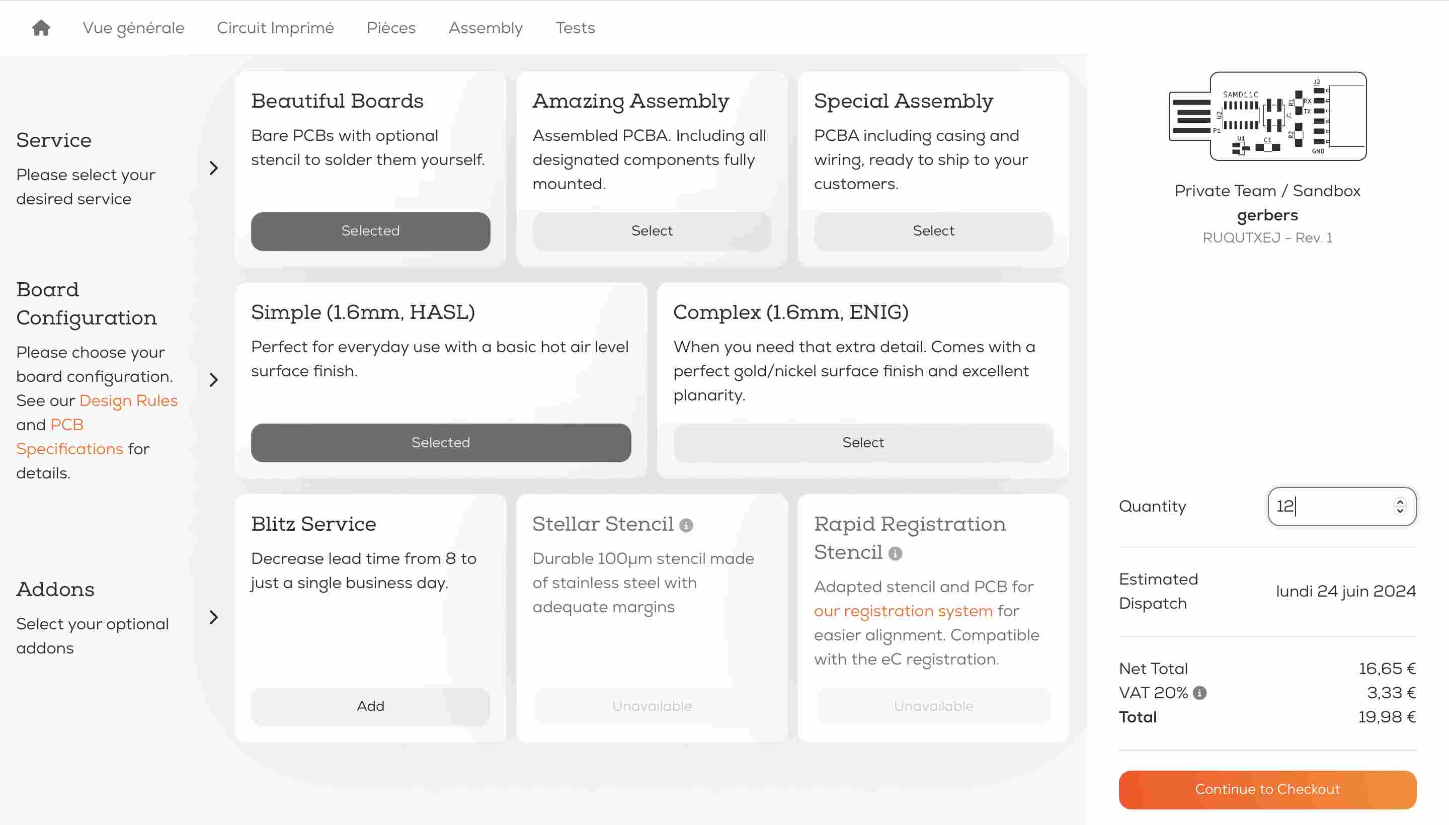
Once all the parameters have been entered, you can enter a delivery address, a billing address and a payment method.
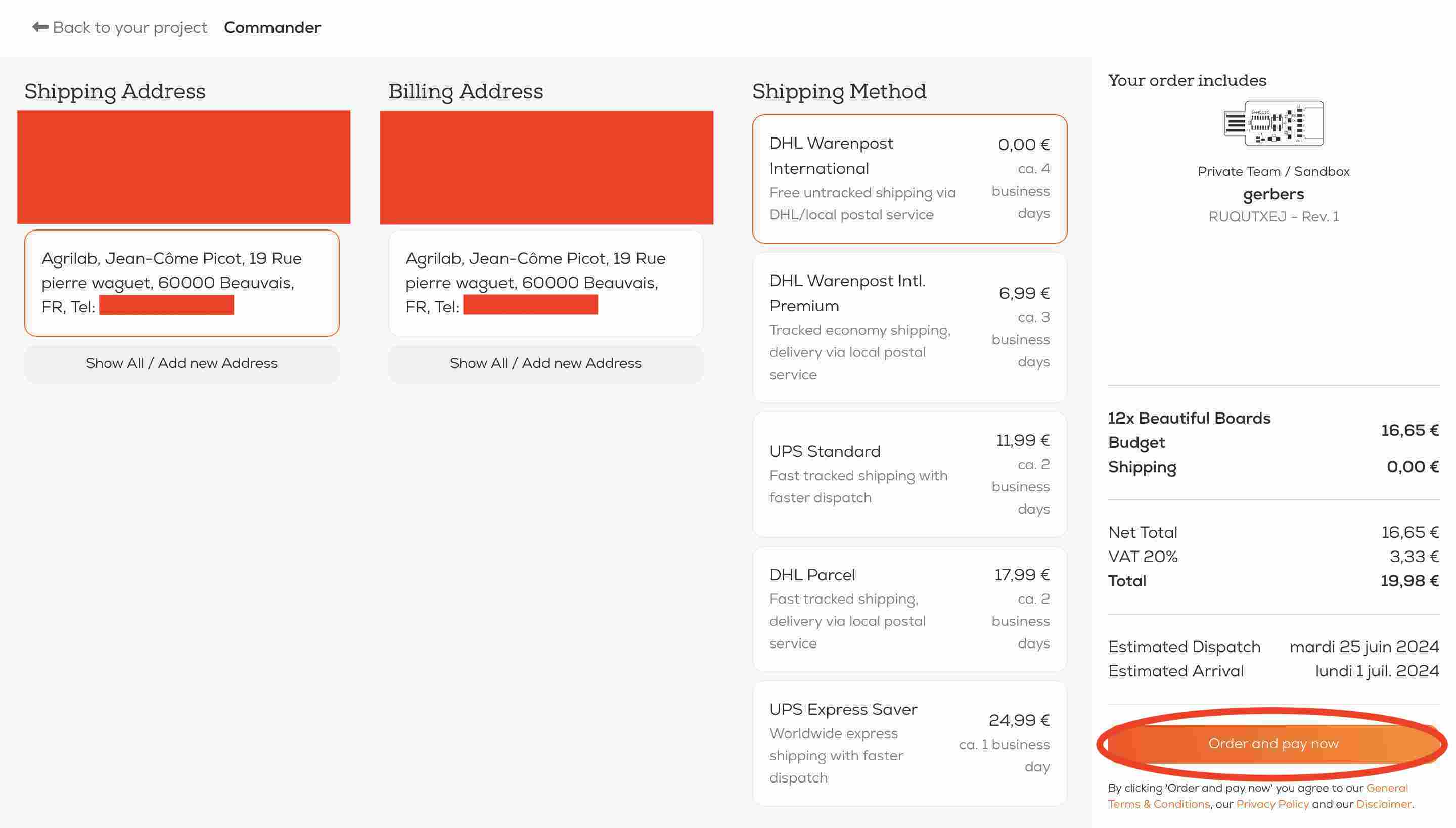
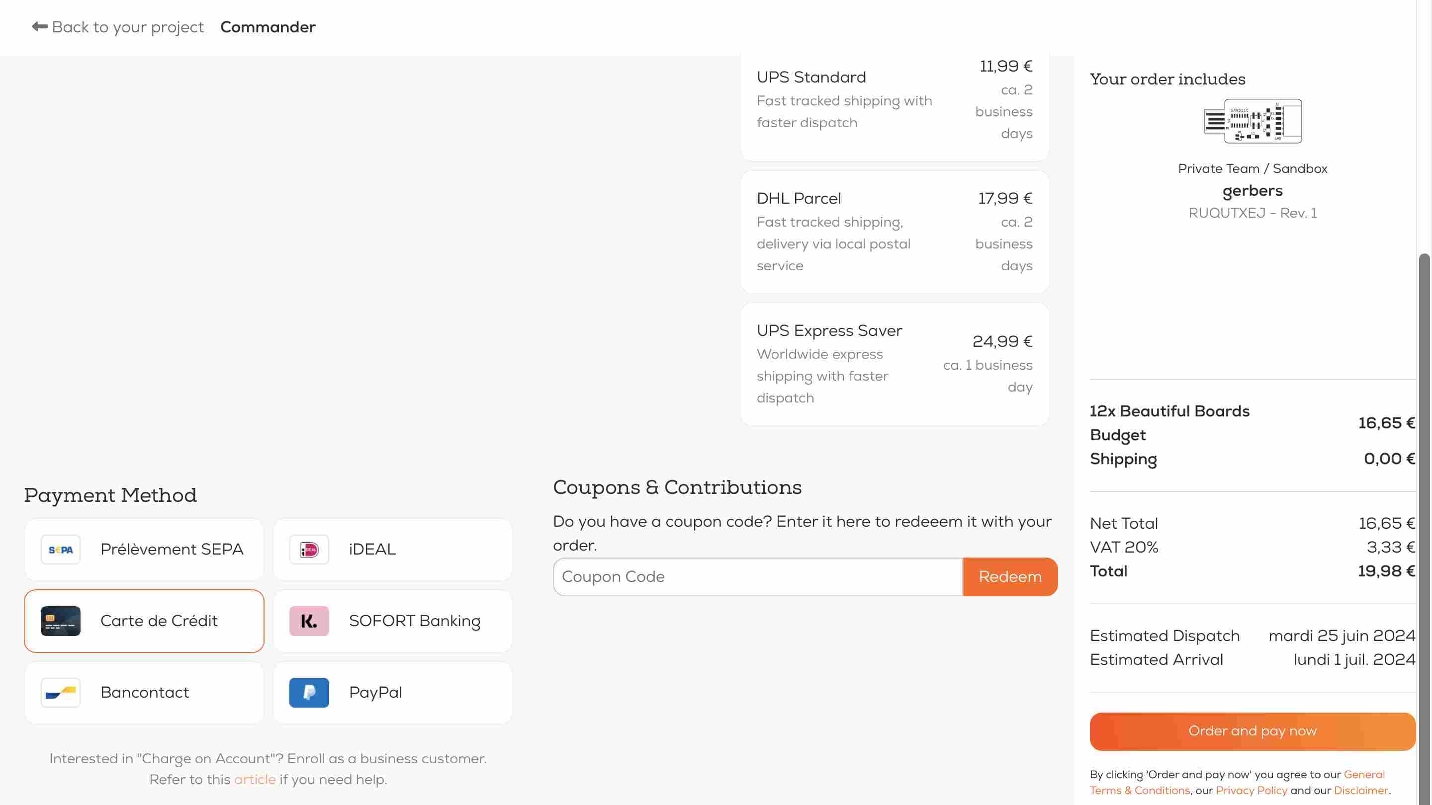
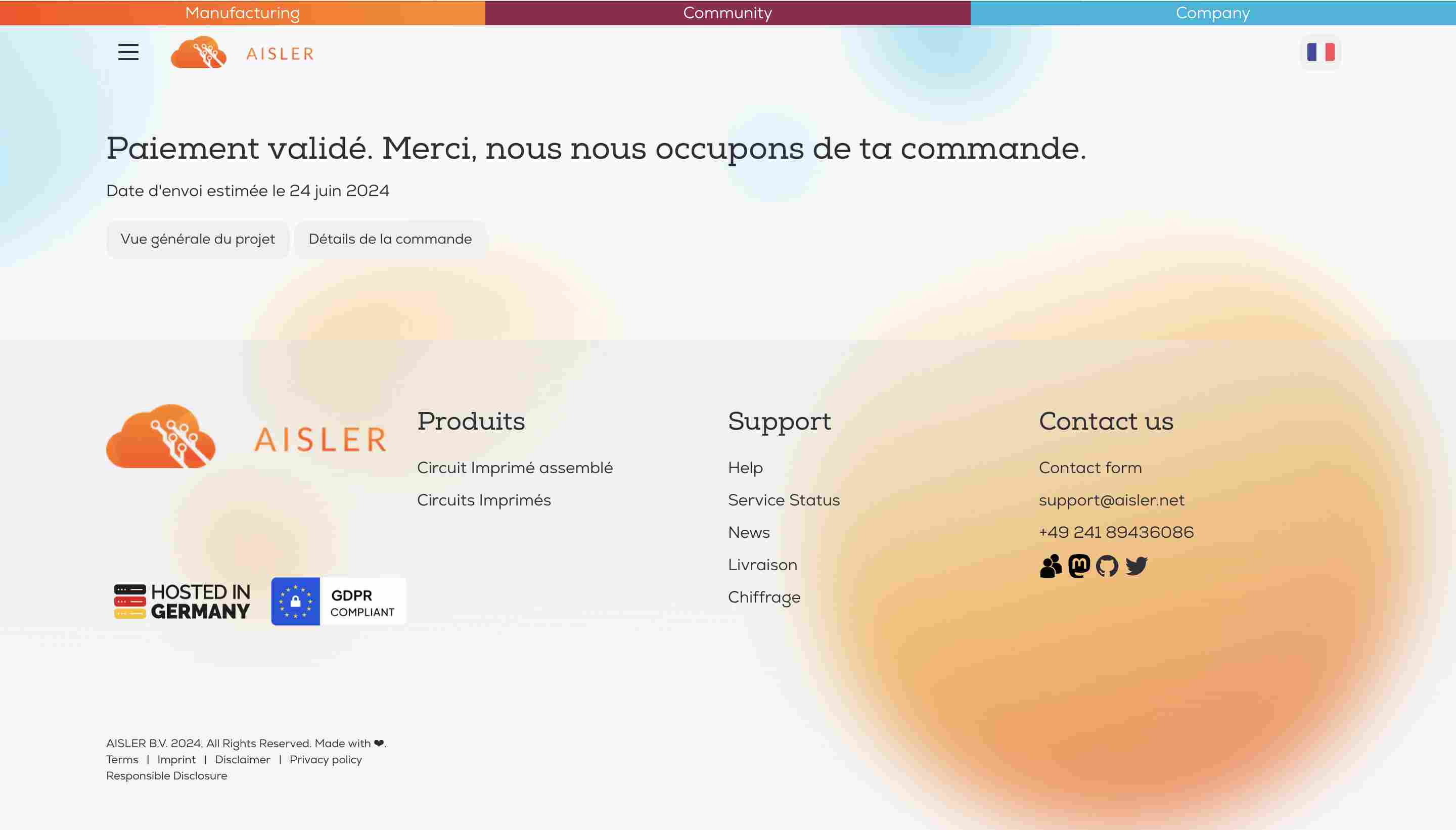
Then all we have to do is proceed to checkout, and once everything is finalized, we receive a message that our order has been taken into account.
Individual assignments
During this week, we had to build and test a microcontroller development board. The board we had to develop is called Quentorres, it can be used as a programmer and was designed by Quentin Bolsée and redesigned by Adrián Torres. In order to create it, all the documentation for the board can be found here, including the documents for producing the PCB, the components it contains and how to use it.
Manufacture of PCB
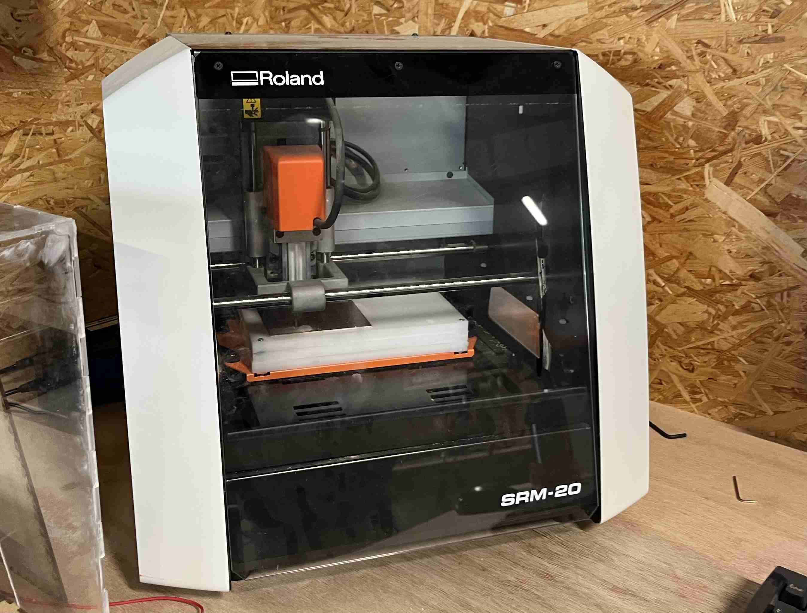
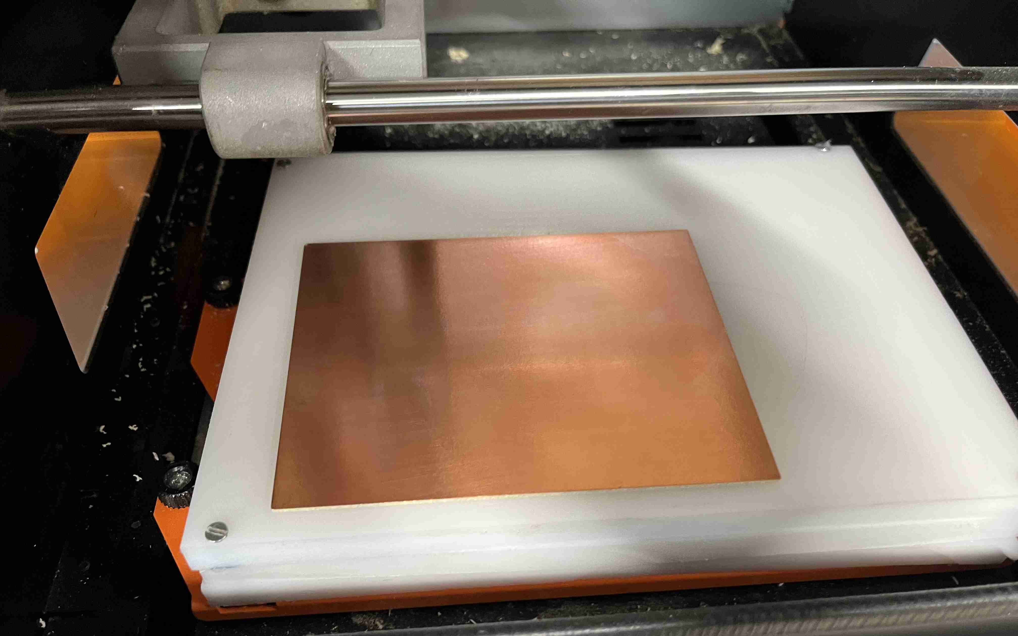
To begin with, the basis of the board is the PCB, which serves as the support and links between the components, allowing us to create something simple and orderly. To do this, we have a Rolland SRM-20 milling machine. This machine is dedicated to milling copper plates for the production of PCB electronic circuits. You can find a page dedicated to it in the Agrilab wiki. It is fairly simple to use and is operated step by step.
Preparing the machine
First of all, you need to put an FR4 type copper plate, i.e. a glass of epoxy underneath the copper to act as an insulator. There are also FR1 cards, which are made of phenolic paper. To fix the copper plate to the martyre (the surface on which the copper will be placed and which will potentially receive blows from the milling cutters), we use double-sided tape, which we apply to the entire underside of the card, taking care not to overlap so that the card lies as flat as possible on the martyre. An offset of just a few tenths of a millimetre could result in poor milling and even breakage of the milling cutter.
Once glued to the martyr, we can now prepare the cutter. To do this, we first need to determine which cutter we want to use according to our needs. We then need to loosen the screw on the head with an XXmm Allen key, pass our cutter through the hole and then retighten it, taking care not to knock it or drop it as it is extremely fragile.
Choosing the millm
I originally chose to mill my PCB using Sorotec's L1S 0.4S L2.0 milling cutters, a single flute milling cutter 0.4mm in diameter and 2mm long. I'd originally used it to test it as part of our group tests and found it to be very satisfactory, even if its long length did make it more fragile - we thought it would break before the end of the test. After an hour of milling my card (1.5 hours in total) the cutter broke, so I opted for a 0.4mm L2SA cutter, again from Sorotec. Finally, for drilling and contour cutting, I used a Sorotec L2SA 1mm cutter.
Origin
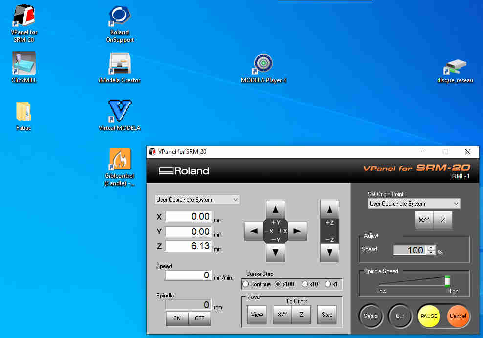
You then need to open the machine's software, in our case VPanel for SRM-20. The software contains various commands, arrows to move the axes and settings. You can start by setting the origin for X and Y. To do this, simply move to the point you want and then press the X/Y button in the "set origin point" menu. For Z, you move slowly towards it using the cursor step, and you can choose how far down you want to go (in hundredths of a millimetre). In my case, for example, I moved down too quickly using the continuous function and the cutter got stuck in the copper; it didn't break but it may have been weakened. Once our cutter is close enough to the copper plate, we can loosen the clamping screw again while holding the cutter and lower it until it touches the plate, then we can tighten it again. As the contact surface is very small, you can simply check that the cutter is lowered using a multimeter. Set it to "contact tester" mode and connect one of the poles to the cutter and the other to the plate. If you don't want the cutter to plunge straight into the material, you can raise the Z axis once the origin has been set.
Personalisation
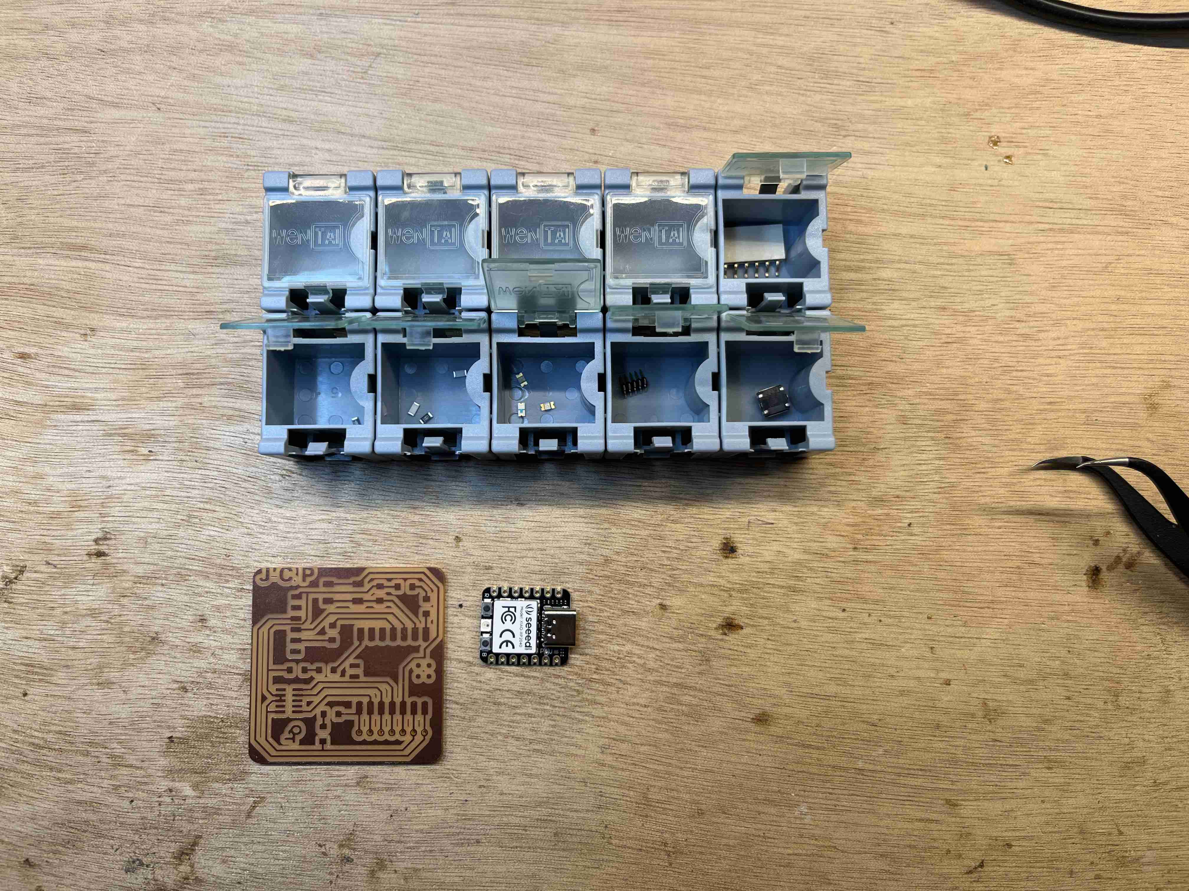
In the assignments, it was possible for us to have an extra credit if we personalised the card, so I gave it a try. As the file I used was in png format, I used krita (raster image software) to modify it. As I didn't have a lot of space, I chose to do something simple by simply writing my initials: J-C.P. To do this, all I had to do was go to the Text and select the area in which you want to place your text. A window will then open where you can enter the content and other parameters such as font, size and so on. Be sure to set the colour to white so that you can see against the black background.
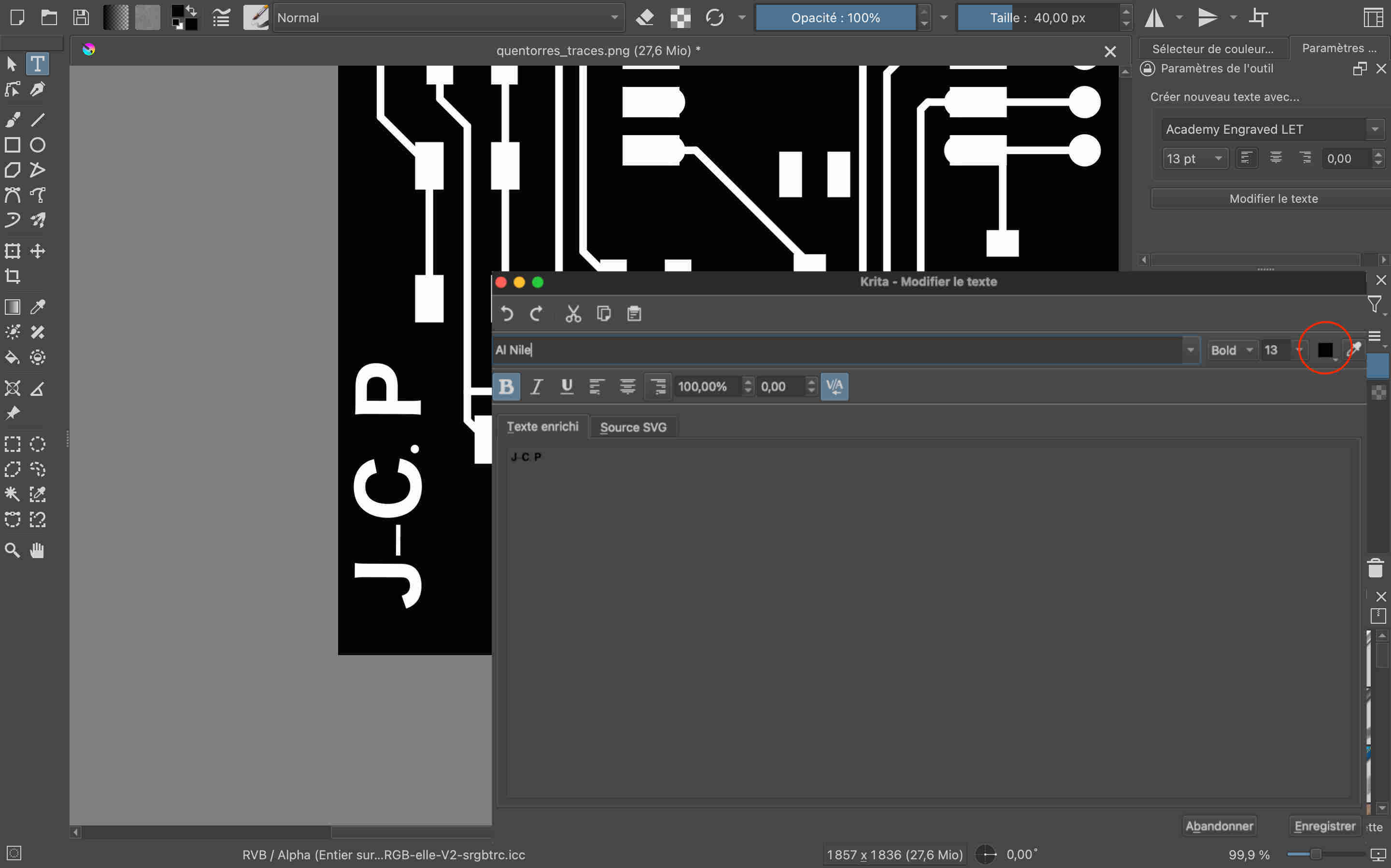
Then simply click Save. With the selection tool, you can then move our model to put it where you want it and readjust it. In my case, we'll see on the cut-out that the font was probably too big and that the top of the letters is right at the edge.
You can find the modified png filehere
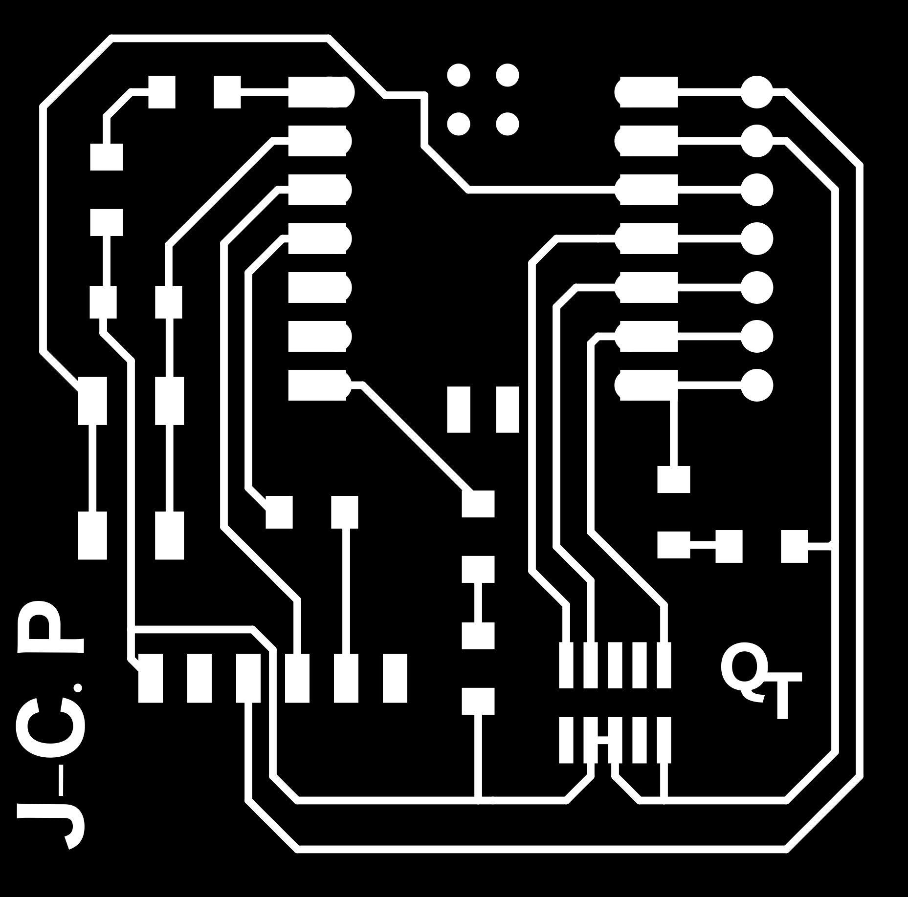
Milling preparation
ATo create the milling cut we want to make, I used the mods, Developed by FabAcademy instructors, it can be used to simplify the use of certain machines, and for example to create the files required for certain machines such as the Rolland.
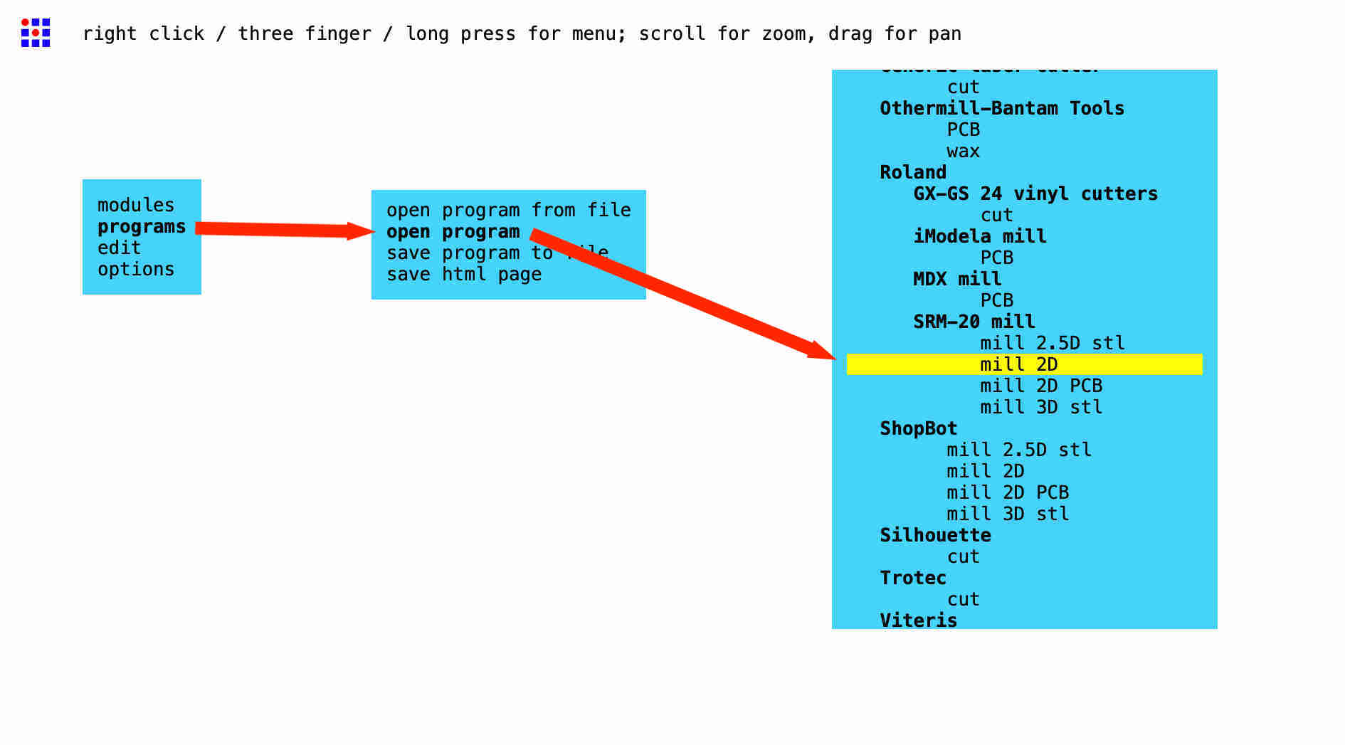
To use it, all you have to do is go to the site and right-click on it. A window will open and you can click on programs another pane opens where you need to select open program, You can then unroll the pane that opens until you find the machine you are using (SRM-20 Mill) or you choose the 2D program mill where this page will open:
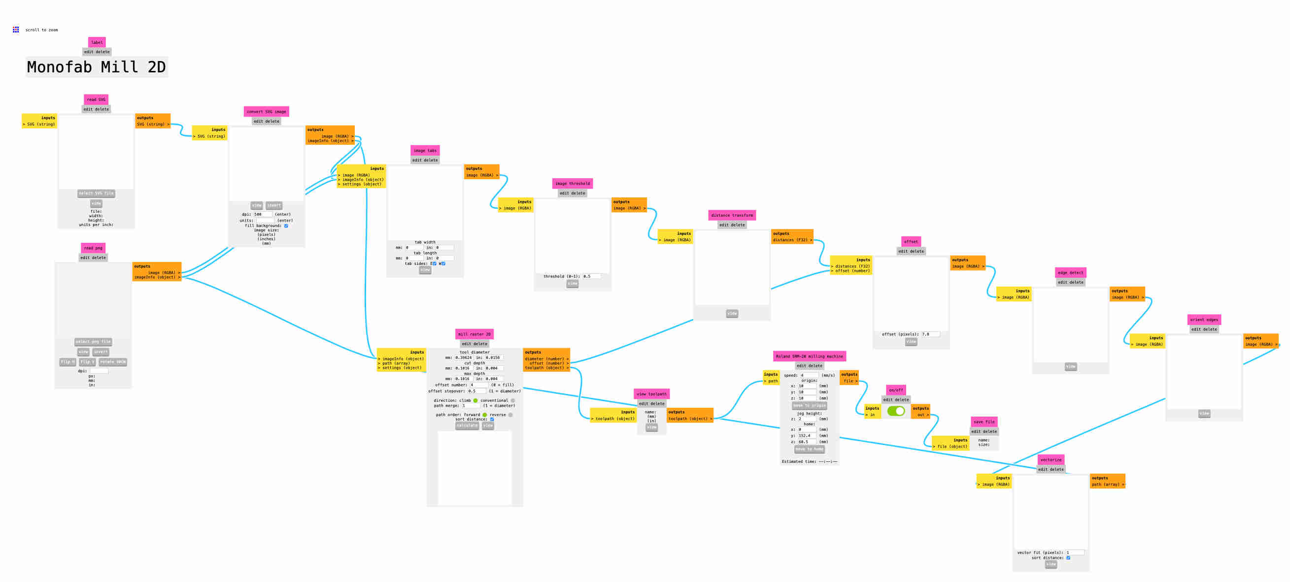
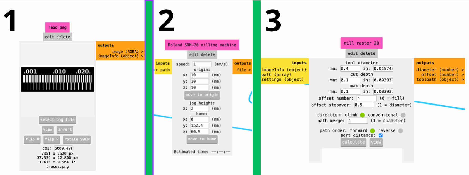
Start at the bottom left by selecting read png, the png file you want to use on the right, then the menu Rolland SRM-20 milling machin where you enter the speed you want for the first milling cutters, I've worked with a speed of 1mm/s in view of their potential fragility, but for the next more robust ones, I've made the tool work at 1.5mm/s. As for the origins, I've set them all to 0 so that the origin of the file is the same as that of the machine. You can then go to the mil raster 2D, Here we enter the diameter of our cutter, in my case 0.4mm. You then need to enter the cut depth, which corresponds to the milling depth per pass, and the max depth, which corresponds to the total depth. To make the traces, I entered 0.1 for the 2 values to have just one pass, but for drilling and contours, I made passes at 0.4mm depth with a max depth of 1.8mm. This depth corresponds to 0.2mm more than the thickness indicated by the seller. Bantam tools son the copper plates. This margin is used to ensure a good cut without damaging the martyrdom thanks to the thickness of the tape. Now that all the values have been entered, you can press calculate, which will create our .rml, format from Rolland, the machine manufacturer. The file downloads automatically and is ready to be opened with the machine.
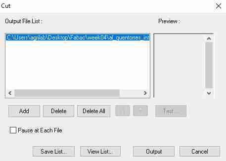
To start milling, select the cut button in VPanel and a window will open. By default, all files are deleted by clicking on delete all puis sur add, Then choose our file and click Outpout , and the milling operation will begin.
The card is created using a series of holes, the first of which is used to delimit all the marks using a 0.4 mm milling cutter, the second to drill the holes and the last to cut the outline, both of which are done using a 1 mm milling cutter. It is preferable to carry out the actions in this order, so that the plate is held securely until cutting.
Soldering
Now that the circuit is properly milled, we can proceed to assemble all the components. The development board that controls our PCB is a XIAO-RP2040, a very small card offering 2 buttons, 11 digital / 4 analog pins, 1 I2C interface, 1 UART port, 1 SPI port, and 1 SWD Bonding pad interface.
Then there's a whole list of components, which can be found in the board's documentation. On the other hand, we have a lot of components that don't match those on the site, so I'll include the links for these components. The only component we haven't used is the conn header for the board. We chose the model where the board is soldered directly to the PCB, so we didn't need it.
The different elements of the documentation we have used are the leds as well as the button. JI'm going to explain how to go about finding the technical data for our component. Taking leds as an example, we have this bag of light blue leds at Agrilab:
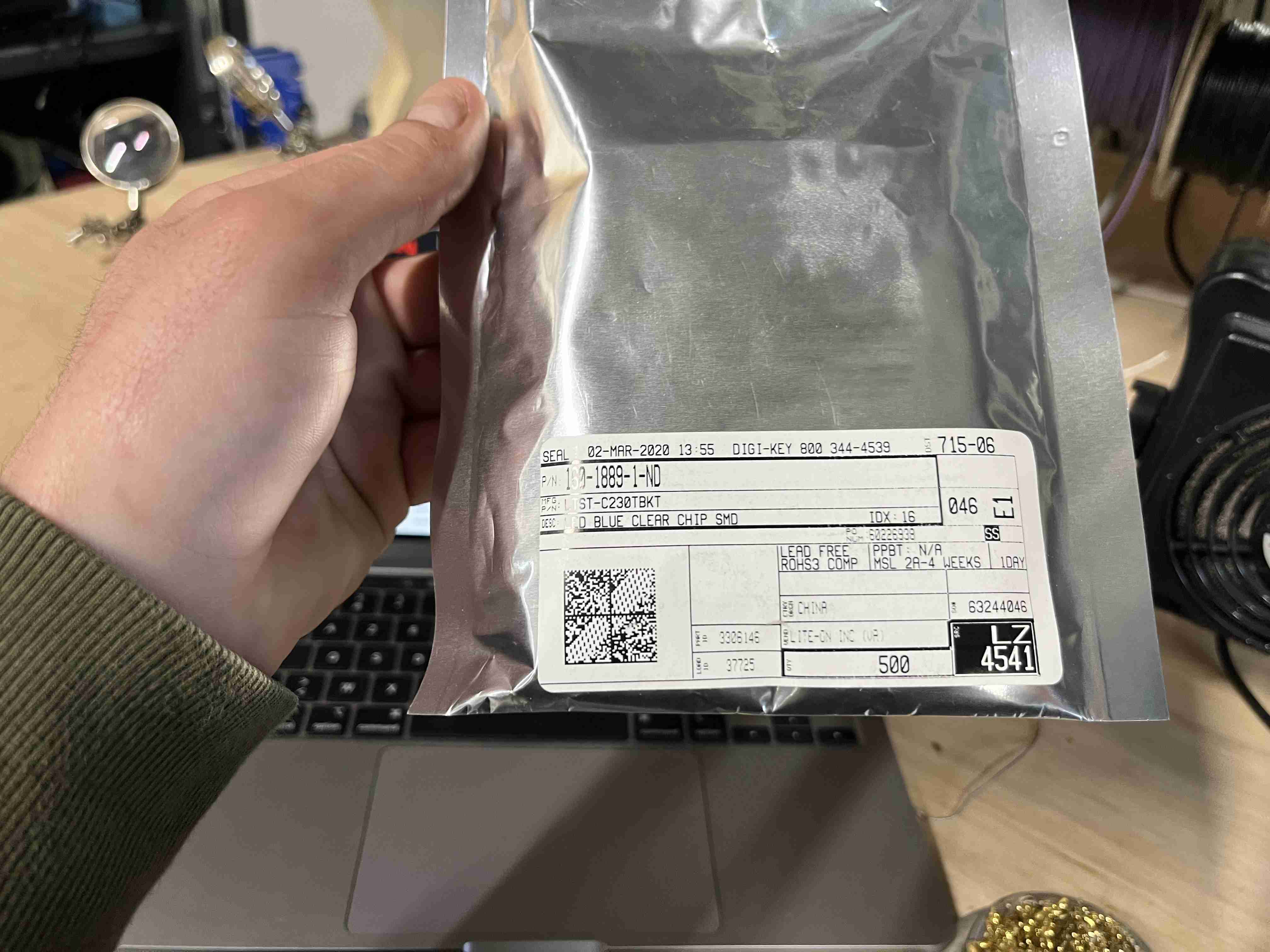
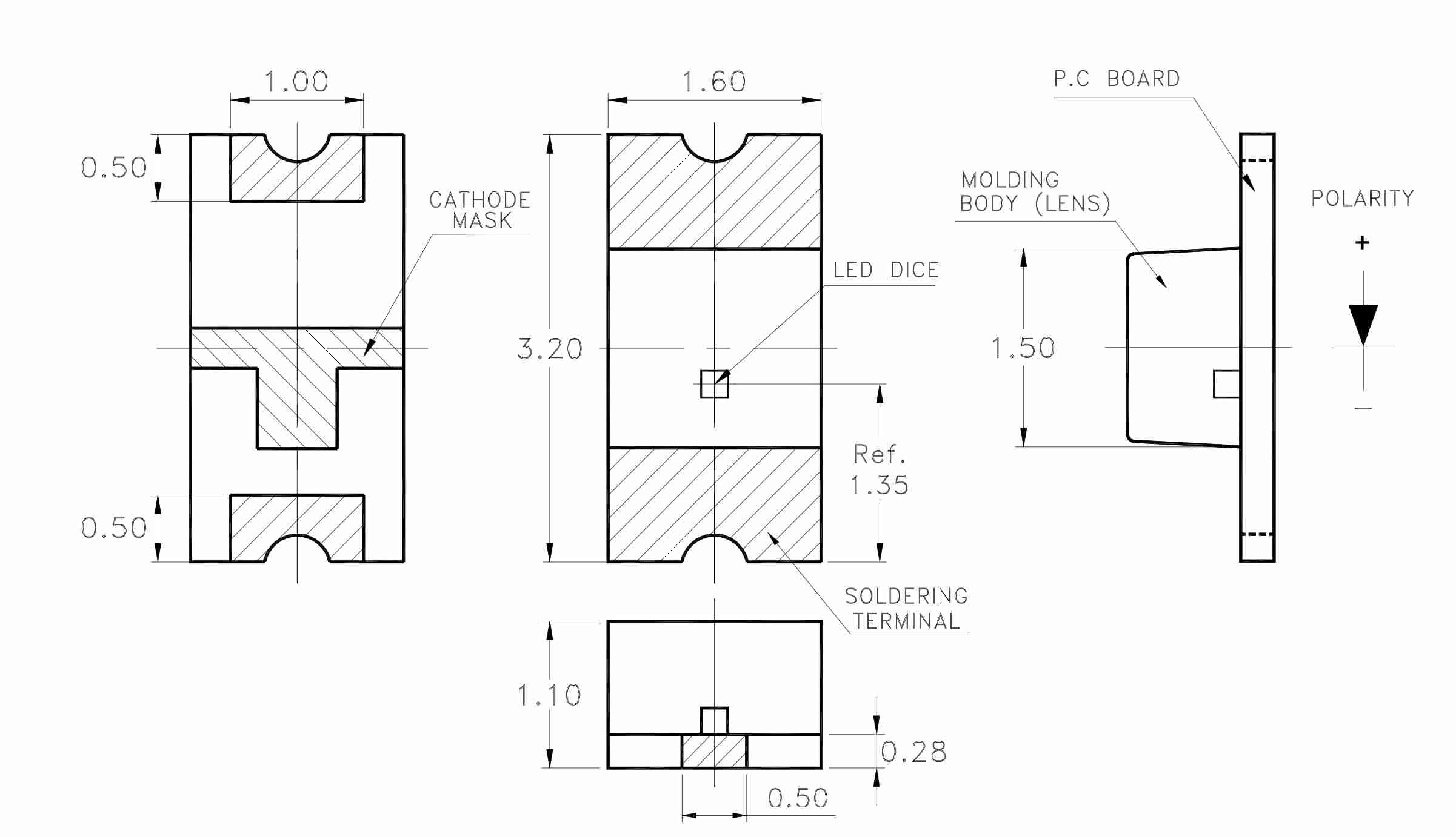
The reference can be found at LTST-C230TBKT and were purchased on DigiKey. All you have to do is enter the reference number on the site and you'll be taken to the page for the led we have. Here you can find the datasheet where you can see what it means, what the different colour markings and operating polarity mean, and much more.
This research can be carried out for the various components we have to determine how they work and how to use them.
Once all the components had been collected, I equipped myself with boxes to store them, putting the different components in each compartment. These boxes have antistatic properties that mean they don't affect the electronic operation of the components.
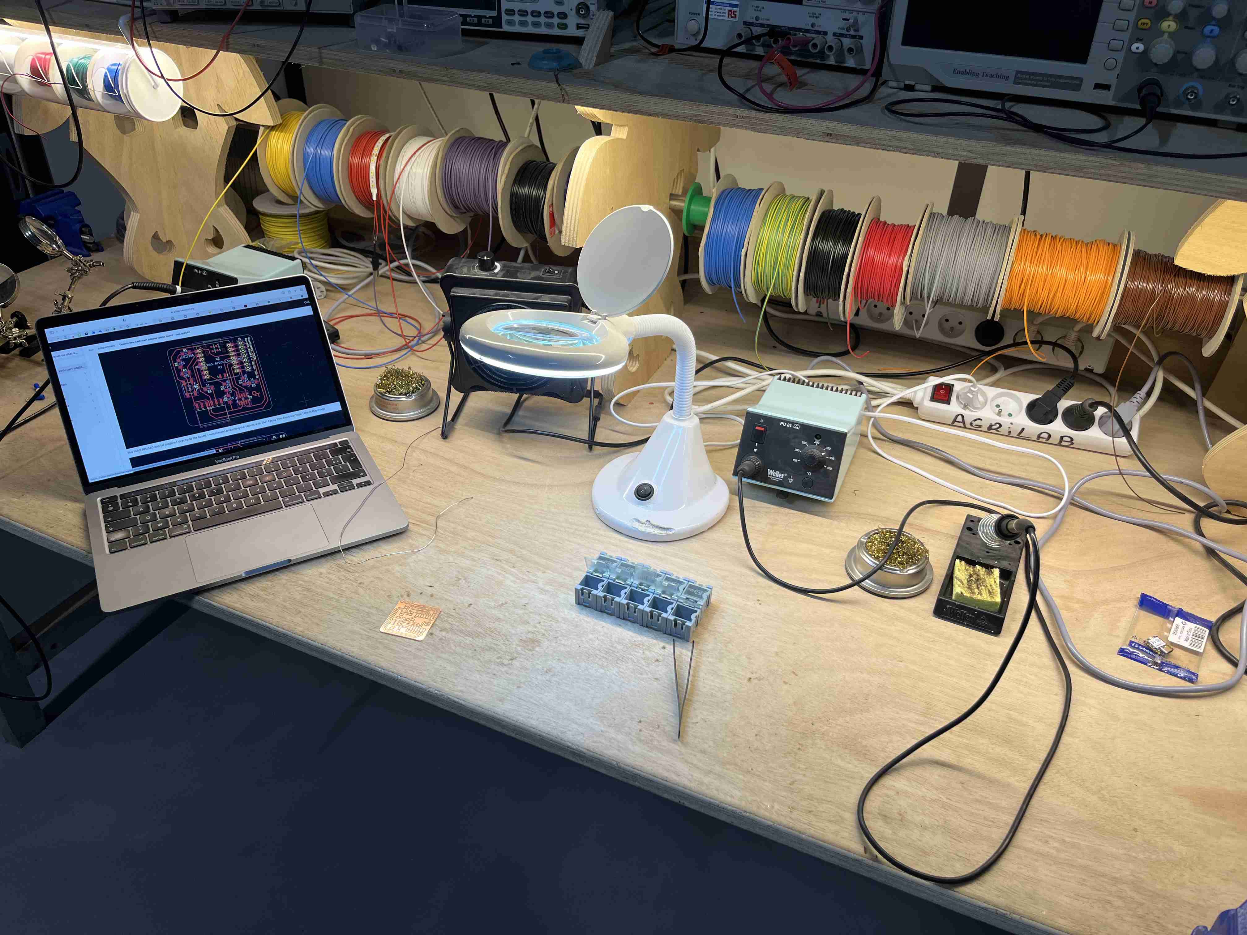
Here's the work surface I used to do my soldering, it includes a soldering iron set at 350°C, steel wool to clean the tip, tin wire, a smoke extractor to suck out the fumes produced by melting the tin, an illuminated magnifying glass, all the components I had to assemble and my computer with the board layout so I knew the precise location of the various components and the direction if there was one, for example for the LEDs.
I then proceeded to solder all my different components, trying to start in the middle and work my way outwards as I went along. I started by soldering all the small parts like the LEDs and resistors, then I went on to the bigger parts. Like the RP2040 or the button.
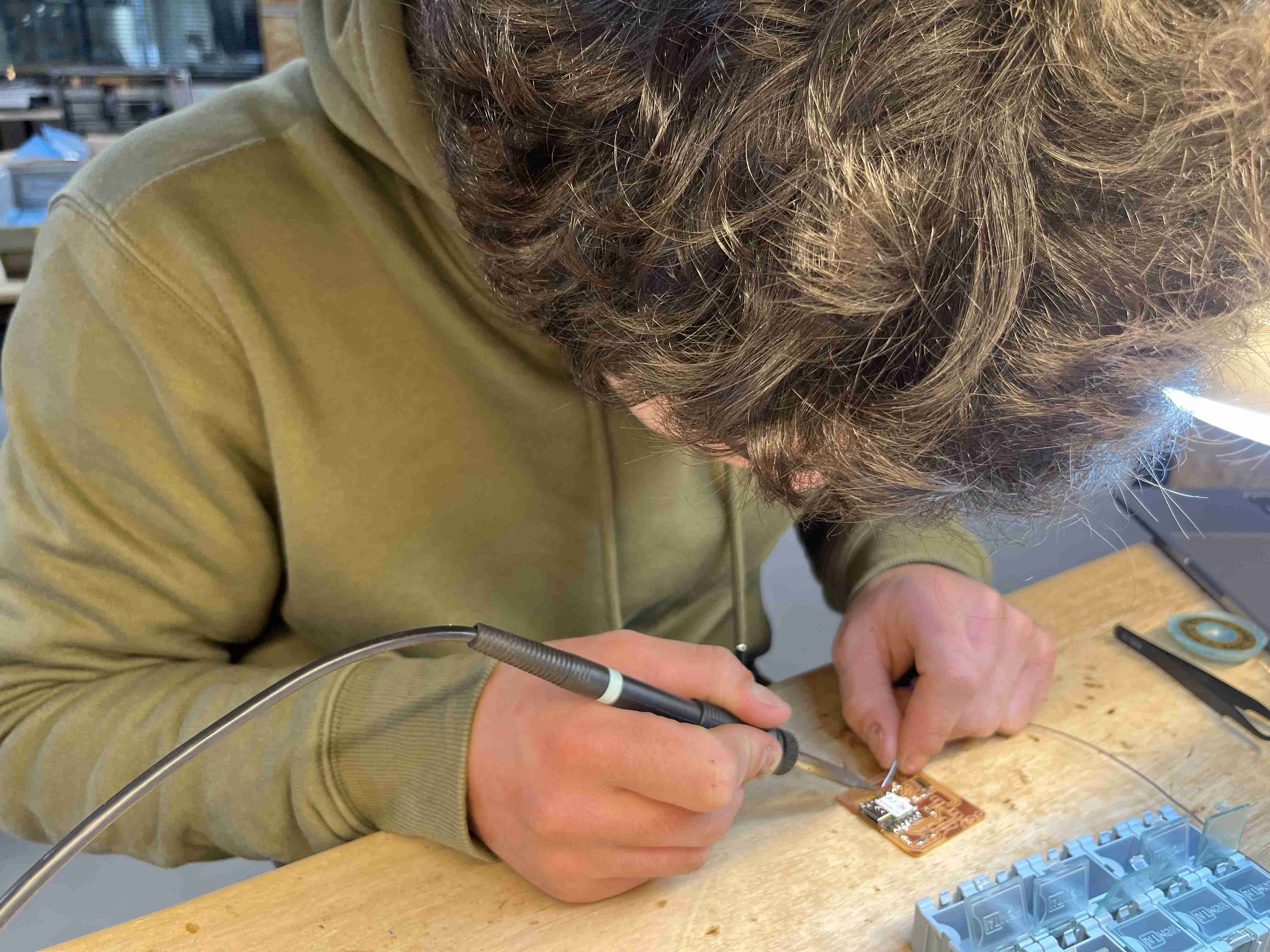
It was complicated to solder the components precisely, but I managed to do it. I'd already practised soldering during the bootcamp and that helped me a lot.
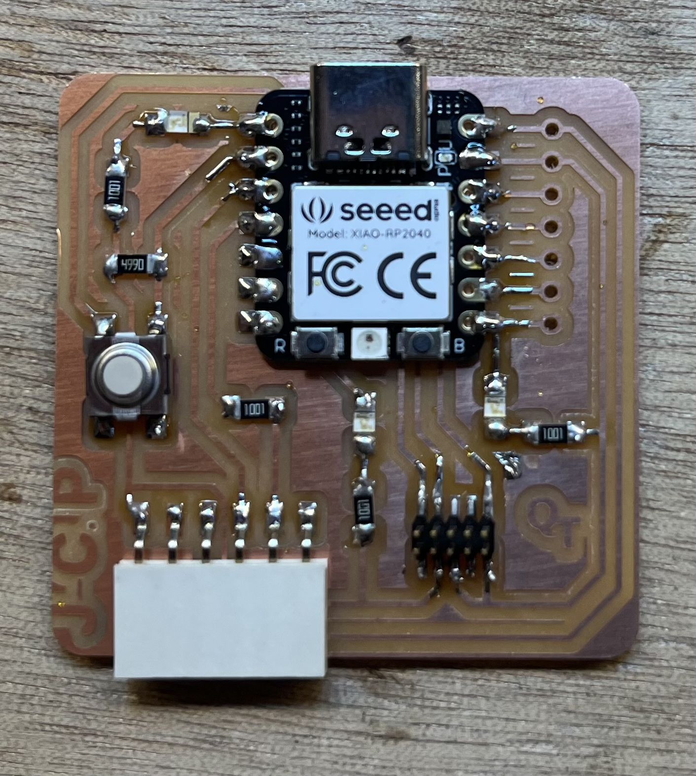
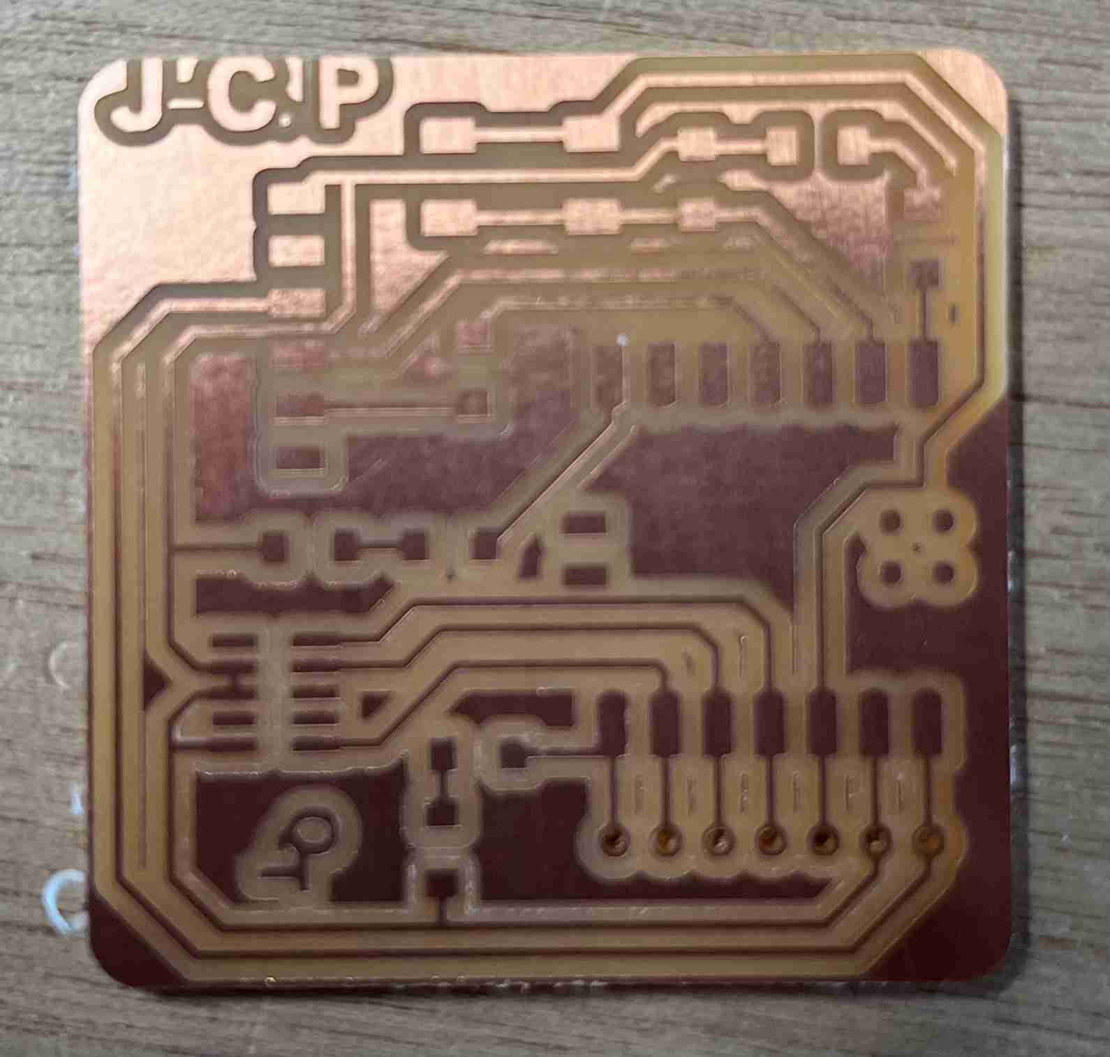
Here's the final rendering of the circuit I made:
Using the board
To carry out these next steps, I used the documentation from the quentorres board and this page github.
Download pico
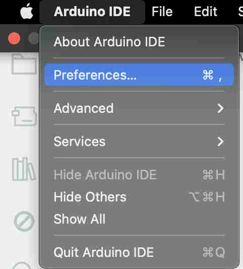
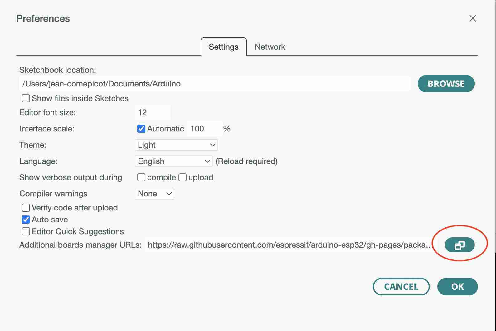
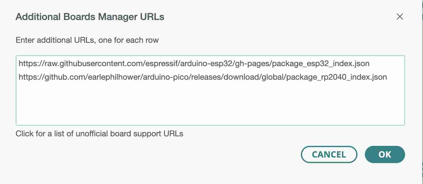
To get started, you need to download the pico library, which enables you to use the Arduino IDE on other electronic boards. To do this, go to the Arduino IDE and select preferences, aller à la ligne Additional Boards Manager URLs, click on the button to modify and add this link:
https://raw.githubusercontent.com/espressif/arduino-esp32/gh-pages/package_esp32_index.json
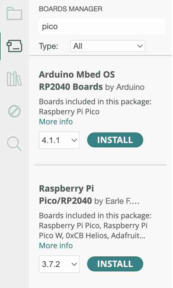
Then go to the board manager and search for our bookseller in pico locurence, then click on Install under the bookshop Raspberry Pi Pico/RP2040.
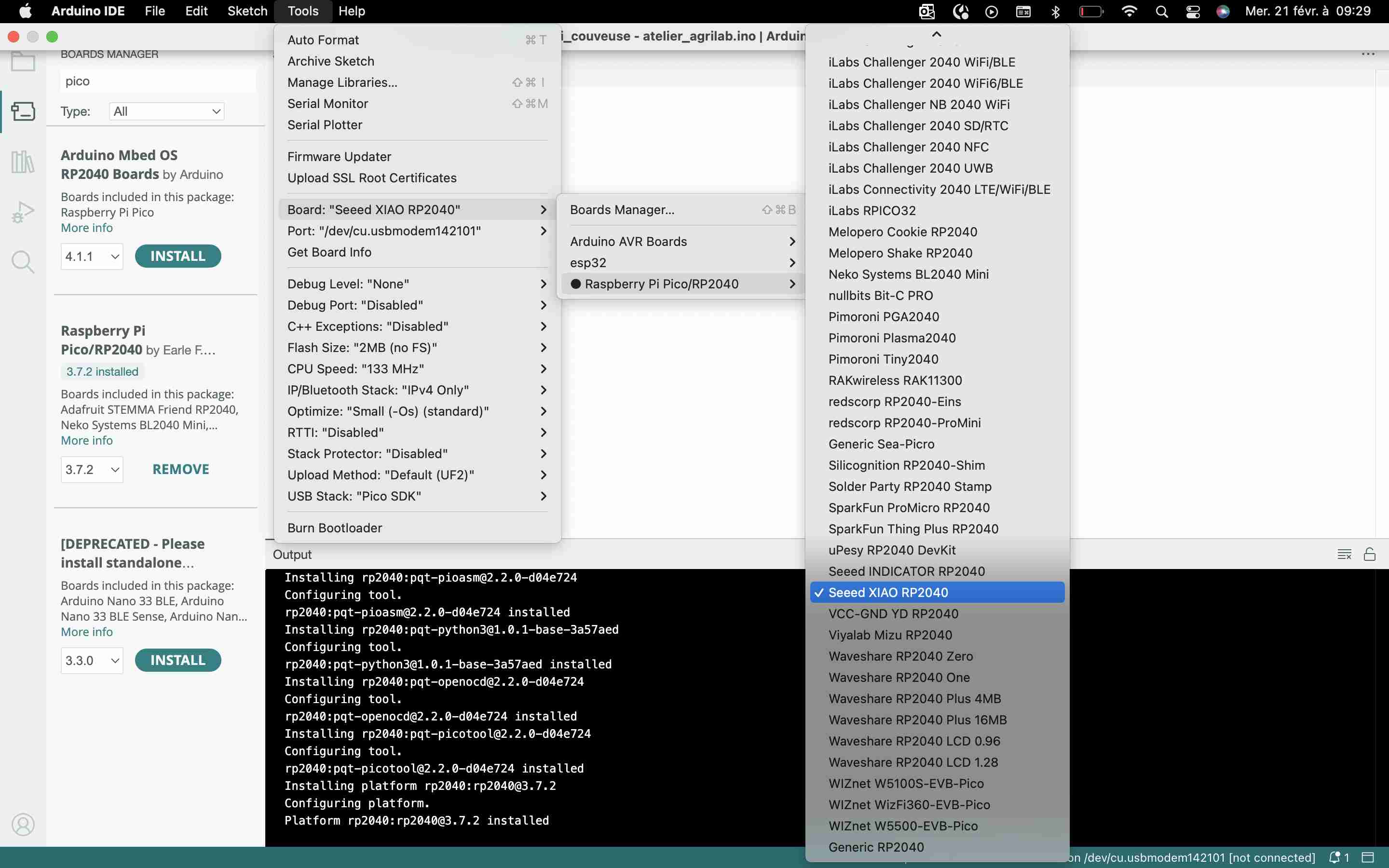
We then wait a few moments for the library to download and then we're ready to use it. To do this, just go to Tools > Board>Raspberry Pi Pico/RP2040 > Seeed xiao RP2040.
Now that everything is ready, we can try out the blink, by going to File > Exemples > 01.Basics > Blink
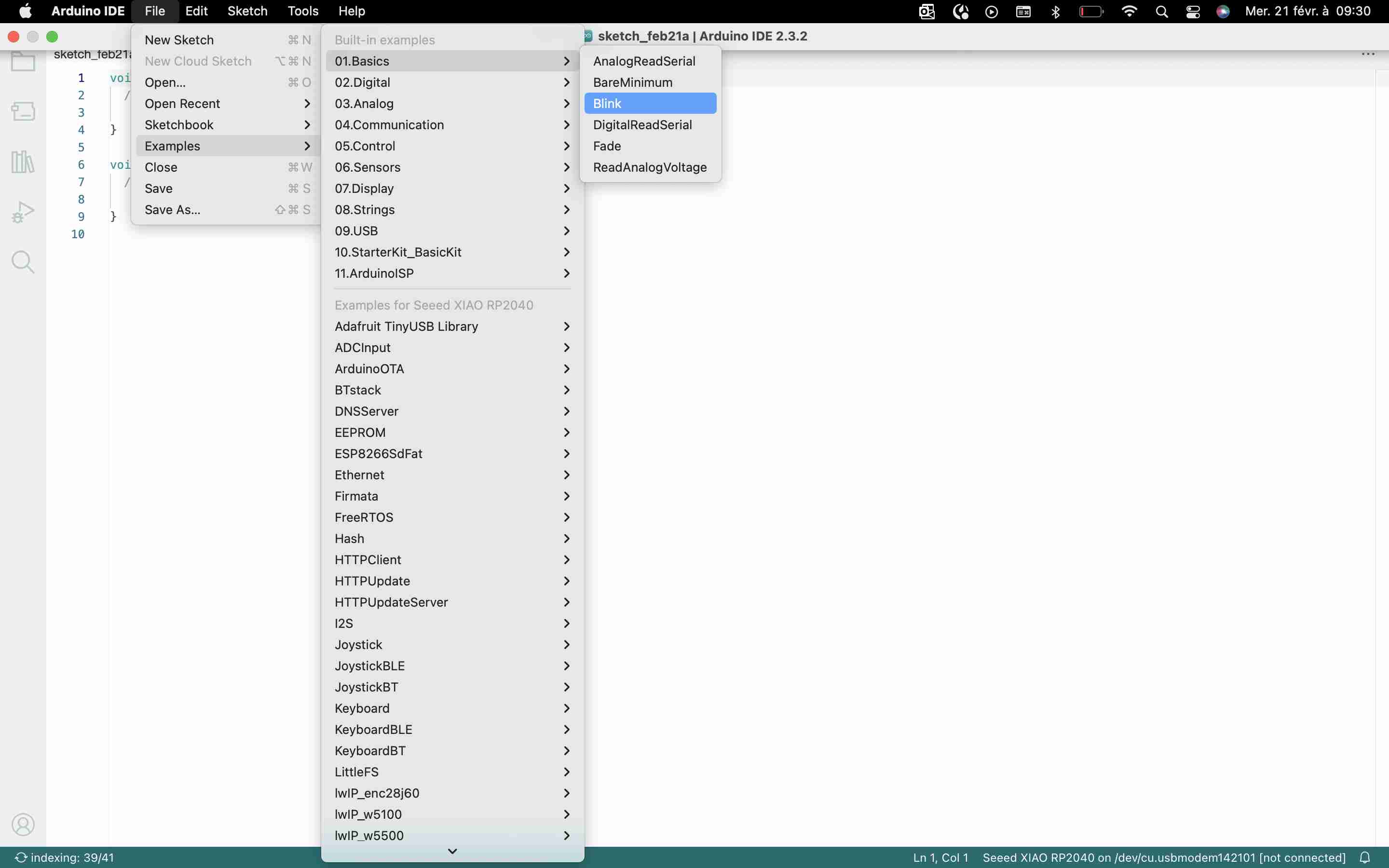
This will open the blink file, but I've modified it slightly to activate the three LEDs on my PCB and I've split the delay into half-seconds rather than seconds.
For do that I used the following code:
// the setup function runs once when you press reset or power the board
void setup() {
// initialize digital pin LED_BUILTIN as an output.
pinMode(26, OUTPUT); //Led
pinMode(0, OUTPUT) ;//Led
pinMode(1, OUTPUT); //Led
pinMode (LED_BUILTIN, OUTPUT) ;
}
// the loop function runs over and over again forever
void loop() {
digitalWrite(26, HIGH);// turn the LED on (HIGH is the voltage level)
digitalwrite(0, HIGH);// turn the LED on (HIGH is the voltage level)
digitalwrite(1, HIGH);// turn the LED on (HIGH is the voltage level)
delay(500);// wait for a second
digitalwrite(26, LOW);// turn the LED off by making the voltage LOW
digitalwrite(0, LOW);// turn the LED off by making the voltage LOW
digitalwrite(1, LOW);// turn the LED off by making the voltage LOW
delav(500):// wait for a second
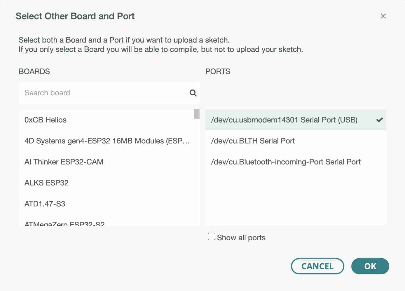
Once the card is connected to the computer, you can click on Upload in order to send the code to the card. You must remember to select the port so that the IDE can communicate with the card.