During this 9th week, we were interested in the outputs that could be used in any way, such as motors, screens, etc. The assignments were as follows
Group asssingment:
measure the power consumption of an output device
Individual assignement:
add an output device to a microcontroller board you've designed,
and program it to do something
Group assingments
In order to make our group assingments, we tested different components with the workshop power supply, for my part, I chose to test the stepper motor that I tried out. To do this, I always kept the same set-up, varying the current as well as the voltage. I noted the results in the form of a table.
| Current | Reaction |
|---|---|
| 0.003 | you can hear clicks |
| 0.035 | Starts to vibrate |
| 0.049 | Start to move |
| 0.07 | The motor is silent |
| 0.08 | Motor no longer vibrates |
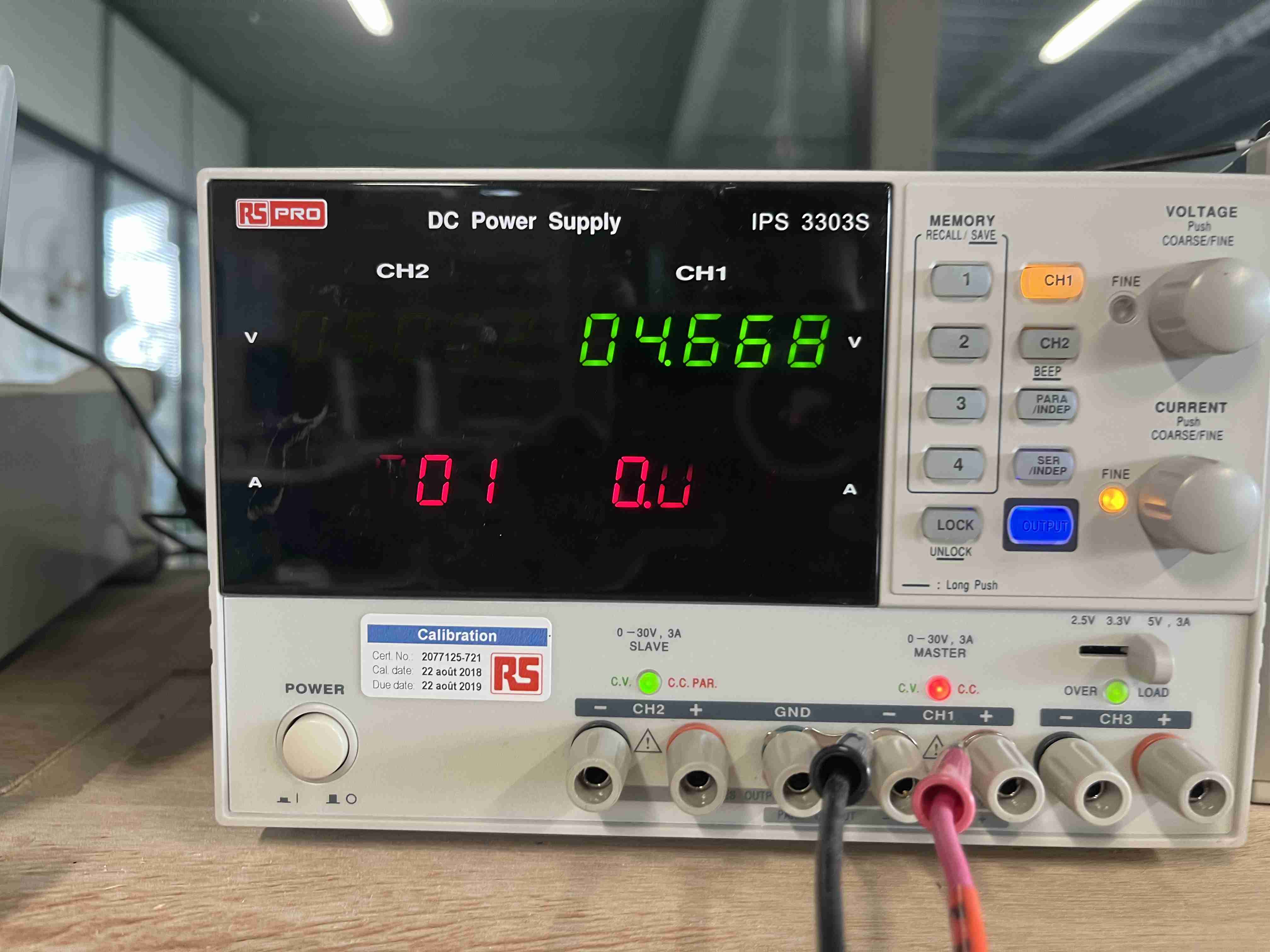
However, when I carried out these tests, the voltage dropped by itself to 4.6 and the motor, although running very well, had almost no torque. So I started again with 12 volts and more current up to 1 amp. The more current I added, the more torque I got.
You can find all of our group assignments on the Agrilab page of the week
Indiviudal assingnment
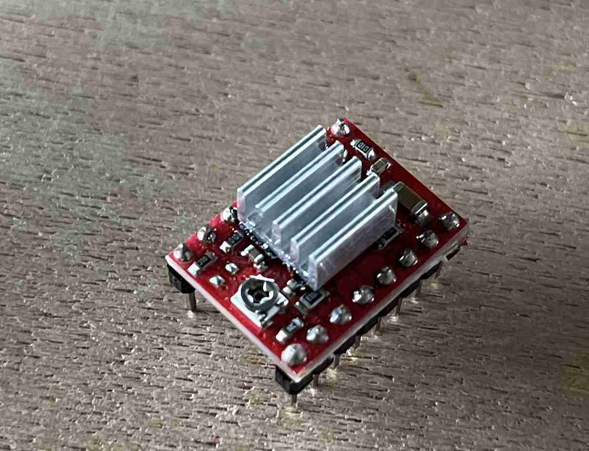
DC motor and driver
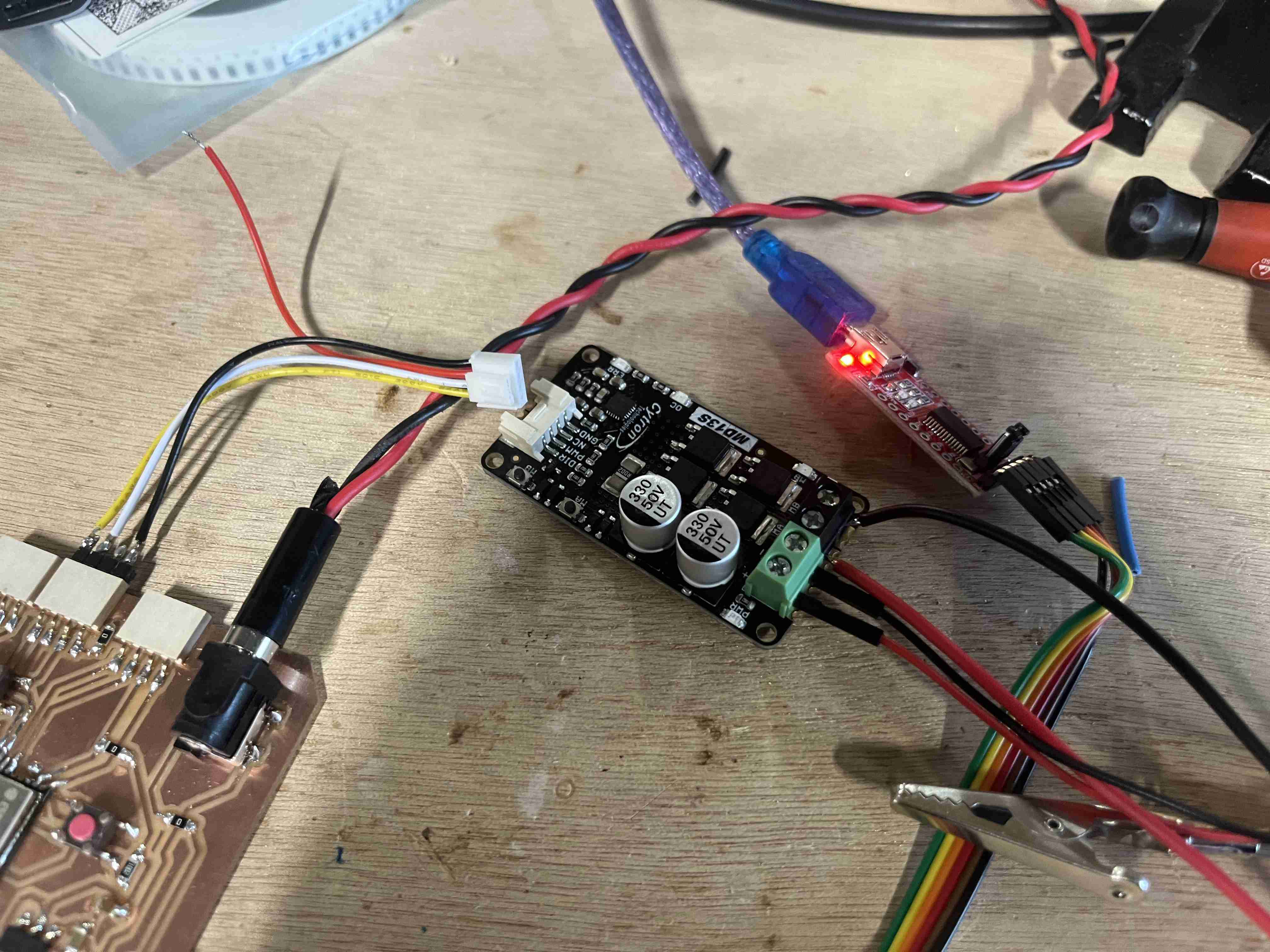
To start my week on output, I took the circuit I made during the week electronic design. The aim of this circuit is to control two motors, a screen and a gps module, so I decided to start by testing a DC motor contrôlé lui même pas un motor driver. I started by soldering the connectors that came with the driver, then I made my connections. I connected the driver in the same way as in the diagram below provided in the datasheet.
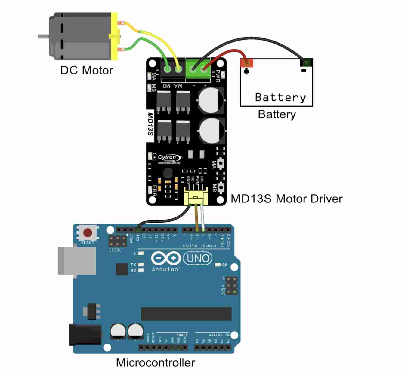
Connect the motor poles to the MA and MB terminals of the driver and supply with a 12V power supply with a + and - on their respective terminals.
As for the driver inputs, I connected 3 of the 4 pins to GND and connected the direction (clockwise/counter-clockwise) to pin33 of my ESP32 and the PWM (used to modulate the speed) to pin 32. Once the connections had been made, I was able to start writing the code
// Define pins for steering control
const int DIR = 33;
//  PWM spindle for speed control
const int PWM_PIN = 32;

void setup() {
  //define the output
  pinMode(DIR, OUTPUT);//direction
  pinMode(PWM_PIN, OUTPUT);//speed
  pinMode(23, OUTPUT);//Led red
  pinMode(21, OUTPUT);//Led green
}

void loop() {
  // Turn the motor clockwise (forward) at medium speed
  digitalWrite(23, HIGH);//led
  digitalWrite(21, LOW);//led
  digitalWrite(DIR, HIGH);
  analogWrite(PWM_PIN, 127); // 50% work cycle (average speed)
  delay(3000); // Wait for 3 seconds

  // Stop the engine
  digitalWrite(23, LOW);//led
  digitalWrite(21, HIGH);//led
  digitalWrite(DIR, LOW);
  analogWrite(PWM_PIN, 0); // Stop PWM
  delay(3000); // Wait for 3 second

  // Running the engine at high speed
  digitalWrite(21, LOW);//led
  digitalWrite(23, HIGH);//led
  digitalWrite(DIR, HIGH);
  analogWrite(PWM_PIN, 255); // Full speed (100% duty cycle)
  delay(3000); // Wait for 3 seconds

  // Stop the engine
  digitalWrite(23, LOW);//led
  digitalWrite(21, HIGH);//led
  digitalWrite(DIR, HIGH);
  analogWrite(PWM_PIN, 0); // Stop PWM
  delay(3000); // Wait for 3 second
}
To create this code I mainly used ChatGPT and the driver documentation. I had difficulty programming the drvier, I thought for a long time that it was the fault of my code which was not good. In reality, after searching for a long time, I found myself thanks to this website that of the ESP32 GPIOs, 4 were not capable of PWM. GPIO 34, 35, 36, 39. So I tried again using the pins found in the programme and I managed to get my motor working. However, I was still having problems with false contacts, and if I moved the wires, the motor stopped working. On investigating, I realised that the problem was with the driver's white connectors. So I soldered some wires directly to the driver and managed to get the motor working without a hitch.
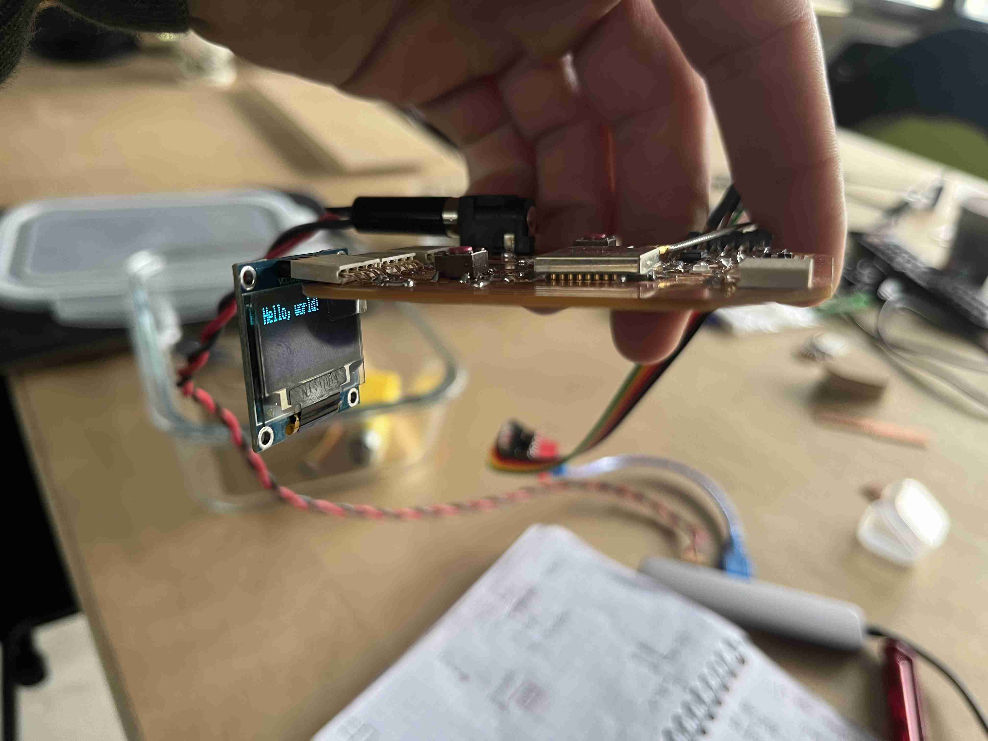
OLED Display
Once I'd managed to use the driver, I wanted to test an I2C OLED screen, we also have LCD screens at Agrilab, but I'd already used them in week 6, Embeded Porgramming.
Knowing that I wanted to test this type of screen, when I designed my circuit I made sure that the pins coincided so that I could connect the screen directly to the circuit in the right order: VCC, GND, SCL, SDA.
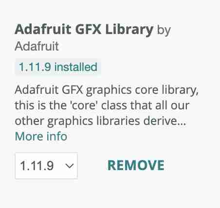
Before creating the code, you'll need to download the Adafruit GFX library and the Adafruit_SSD1306 library, which can be used to control OLED screens.
I then created my code using ChatGPT, which you can find below. It's simply a Hello, world, to test whether I could display things on it.
#include "Wire.h"//library
#include "Adafruit_GFX.h"//library
#include "Adafruit_SSD1306.h"//library

#define SCREEN_WIDTH 128 // OLED screen width in pixels
#define SCREEN_HEIGHT 32 // OLED screen height in pixels

// Pin definition for the I2C bus
#define SDA_PIN 2
#define SCL_PIN 14

// Initialising the OLED screen
Adafruit_SSD1306 display(SCREEN_WIDTH, SCREEN_HEIGHT, &Wire, -1);

void setup() {
  // Initialising I2C communication
  Wire.begin(SDA_PIN, SCL_PIN);

  // Initialisation of the OLED screen with address 0x3C
  if (!display.begin(SSD1306_SWITCHCAPVCC, 0x3C)) {
    Serial.println(F("OLED screen not detected"));//if the screen is not detached
    while (true);
  }

  // Clearing the OLED screen
  display.clearDisplay();

  // Text display
  display.setTextSize(1);      // Font size 1
  display.setTextColor(SSD1306_WHITE); // White text colour
  display.setCursor(0, 0);     // Cursor position
  display.println("Hello, world!"); // Text to display
  display.display();           // Display update
}

void loop() {
  // Text display
  display.clearDisplay();// Clearing the OLED screen
  display.setTextSize(1);      // Font size 1
  display.setTextColor(SSD1306_WHITE); // White text colour
  display.setCursor(0, 0);     // Cursor position
  display.println("Hello, world!"); // Text to display
  display.display();           // Display update
}
I don't know why, but when the screen is connected to the programmer, the code uploading fails, whereas it works fine when I disconnect it.
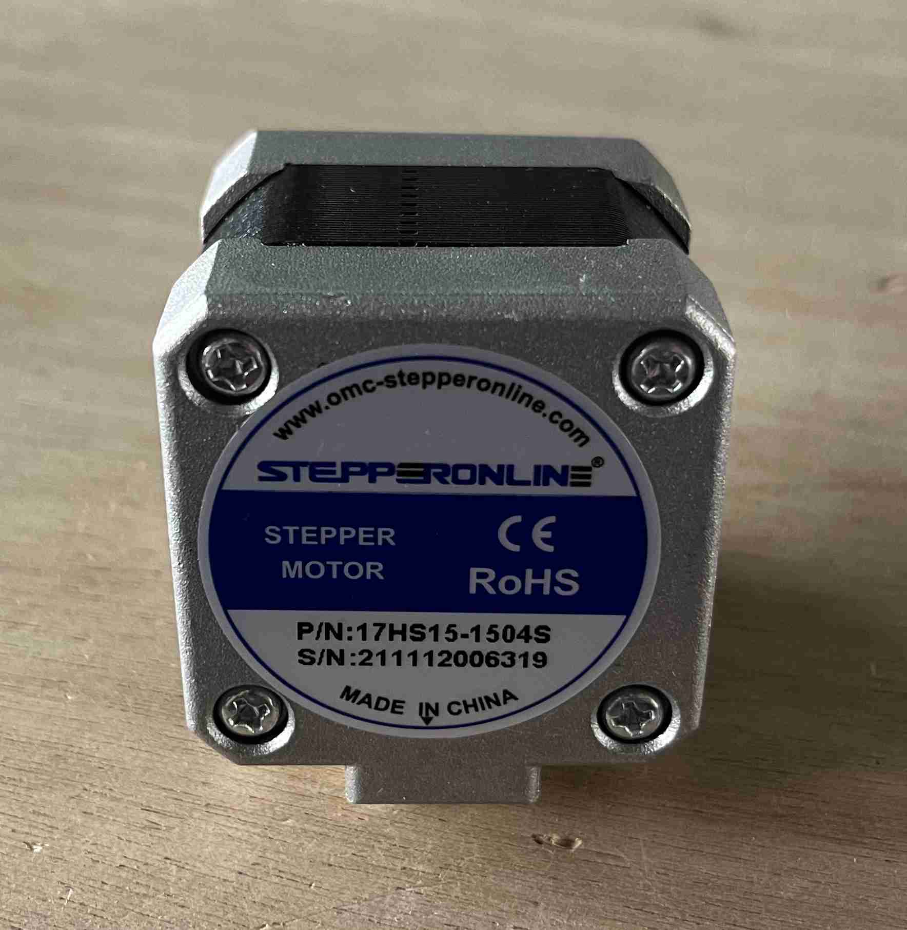
Stepper motor
Next week will be our machine week, and right now we're planning to create a ceramic printer. This kind of machine works in much the same way as a filament 3D printer, so we'll need to use stepper motors to control our various axes and I wanted to test some out first to see how it worked. To simplify my understanding of these devices, I drew heavily on the documentation for the plasma cutter that had been manufactured in 2022 during Machine Week. When it was designed, the machine was equipped with stepper motors and the same drivers, so I simply had to take the code used and try it out. Originally, I wanted to try it out with my own circuit, but given the difficulties I encountered, I decided to use an arduino UNO, which fits in perfectly with the driver.
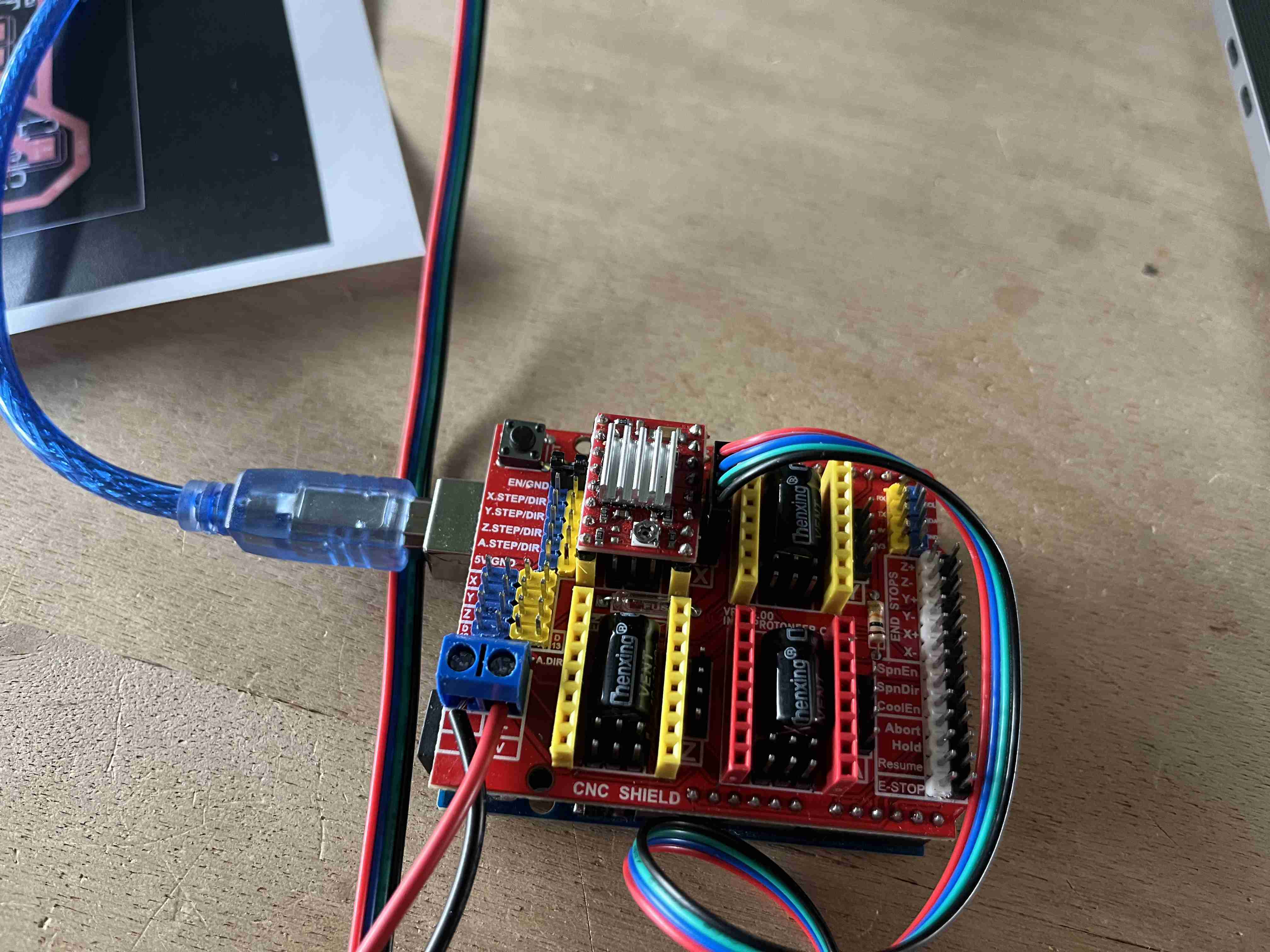
I reused the code that came with the documentation, which was as follows.
// move a stepper motor in one direction and another
int motorpin = 2;  // stepper motor on the pin 2
int dir = 5;// direction control on the pin 5

void setup() {
  pinMode(2,OUTPUT);
  pinMode(5,OUTPUT);
}

void loop() {
  for (int i = 0; i <= 200; i++) {//for a 200 steps motor
  //The motor turn in one direction
    digitalWrite(motorpin, HIGH);
    digitalWrite(dir, HIGH);
    delay(10);
    //The motor is stopped
    digitalWrite(motorpin, LOW);
    digitalWrite(dir, HIGH);
    delay(10);
  }
  for (int i = 0; i <= 200; i++) {
    //The motor turn in another direction
    digitalWrite(motorpin, HIGH);
    digitalWrite(dir, LOW);
    delay(10);
    //The motor is stopped
    digitalWrite(motorpin, LOW);
    digitalWrite(dir, LOW);
    delay(10);
  }
}
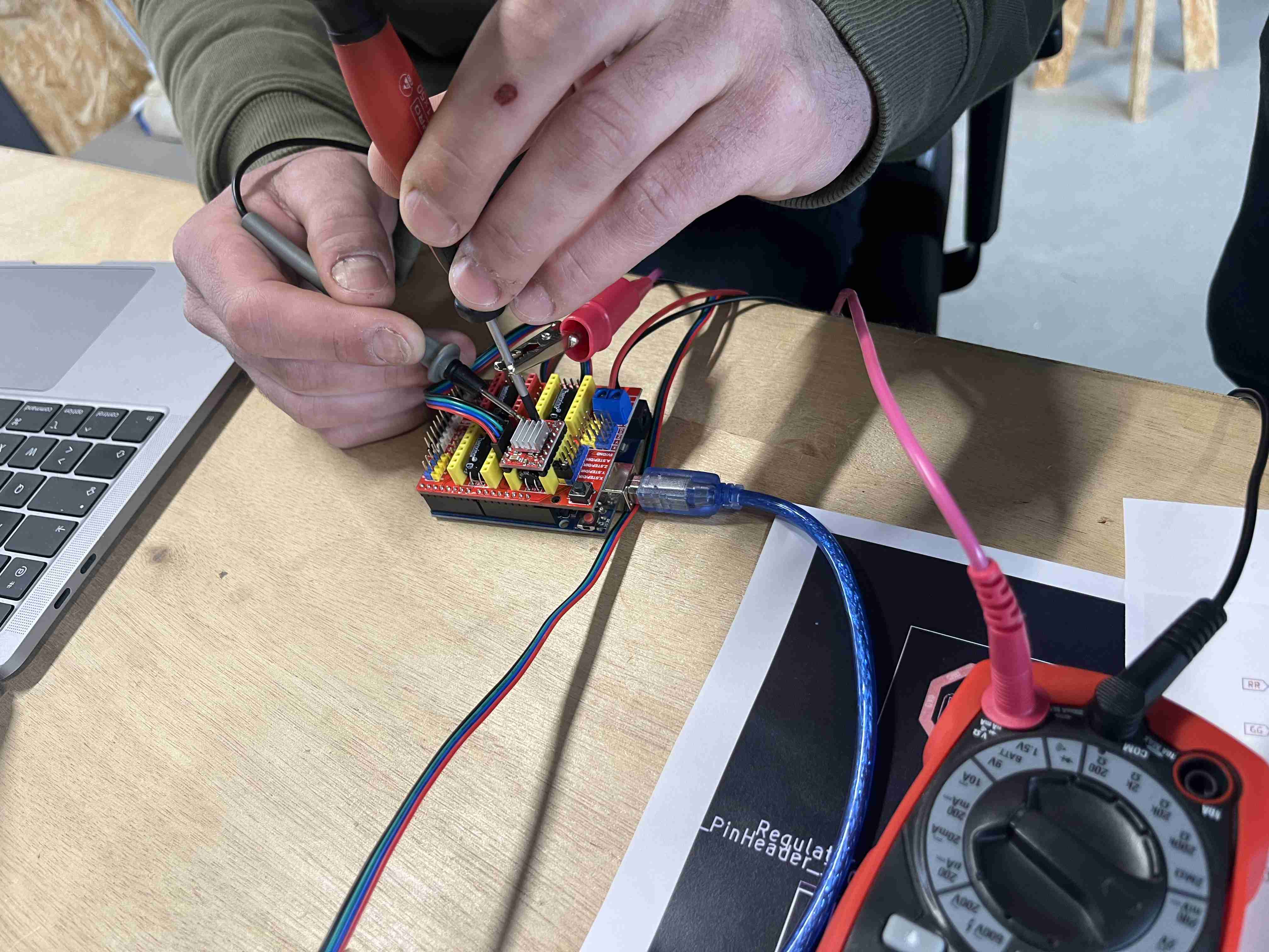
Despite all the different adjustments and voltage tests we were able to carry out, we were unable to get the motor to work. We tested the voltage at all the different terminals as well as the contact to see if everything was coherent and we didn't manage to determine where the problem was. We also checked the relationship between the different wires on the multimeter (black with green, red with blue). We tried again later by simply changing the VREF very slightly (an operation we'd already carried out beforehand) and it worked. We then set it to VREF to get cleaner pitches. When the engine started, it had no torque and shuddered a lot with irregular strides. So we always took our cue from the documentation provided on the cutter, which suggested this calculation:VREF = RMC x 8 x Rsense en using the following values:
| Type | Values | Acronym |
|---|---|---|
| Current Sense resistance | 0.01 Ohms | Rsense |
| Rated motor current | 1.3 A | RMC |
| Safety margin percentage | 25 % | SM |
Using these values, we obtained a VREF calculation of 0.104. By using the multimeter and connecting the annode to the ground and the cathode to the screwdriver, we were able to vary the value in order to adjust our Vref. We need to remember to power the module for this to work. Once we had set the Vref correctly, the motor worked much more satisfactorily.
Loudspeaker
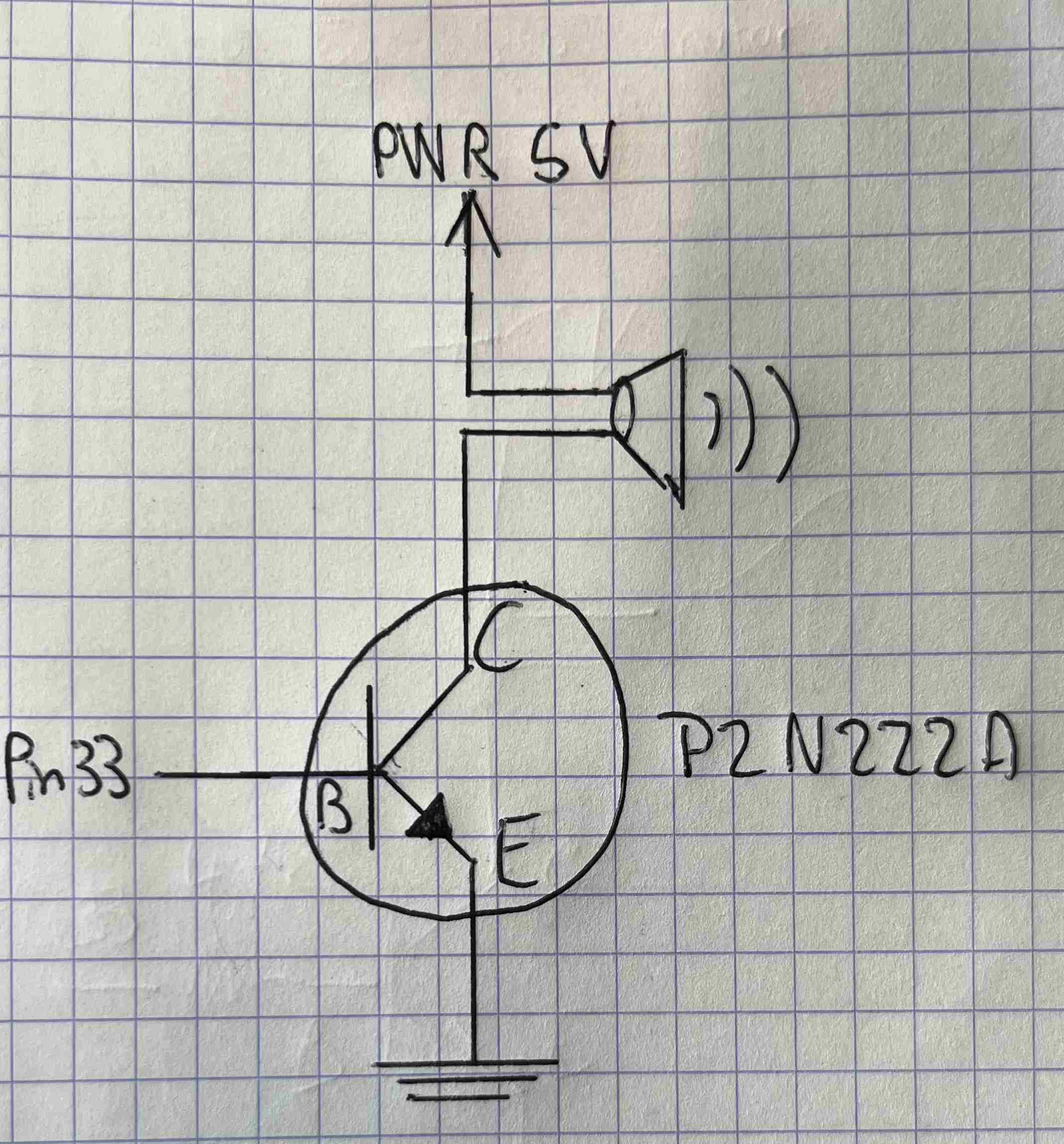
As part of my final project, I might need to make some noise to scare off the corvids. So I wanted to try using a loudspeaker to see if I could use it with my ESP32. So I wired it up in the same way as the diagram below, using this transistor 2N2222.
For the code, I used the Tone melody from the Arduino IDE, simply by changing my pins, the code is as follows:
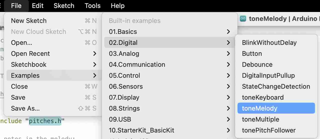
#include "pitches.h"

// notes in the melody:
int melody[] = {
  NOTE_C4, NOTE_G3, NOTE_G3, NOTE_A3, NOTE_G3, 0, NOTE_B3, NOTE_C4
};

// note durations: 4 = quarter note, 8 = eighth note, etc.:
int noteDurations[] = {
  4, 8, 8, 4, 4, 4, 4, 4
};

void setup() {
  // iterate over the notes of the melody:
  for (int thisNote = 0; thisNote < 8; thisNote++) {

    // to calculate the note duration, take one second divided by the note type.
    //e.g. quarter note = 1000 / 4, eighth note = 1000/8, etc.
    int noteDuration = 1000 / noteDurations[thisNote];
    tone(33, melody[thisNote], noteDuration);

    // to distinguish the notes, set a minimum time between them.
    // the note's duration + 30% seems to work well:
    int pauseBetweenNotes = noteDuration * 1.30;
    delay(pauseBetweenNotes);
    // stop the tone playing:
    noTone(33);
  }
}

void loop() {
  // no need to repeat the melody.
}
Once the code had been uploaded and the circuit powered up, I was able to test it on a power supply from the workshop. The speaker capacity is 75 Watts, so the risk of damaging the circuit is very low at the frequencies I use. Here's the result when I run the program
You can see that the result is not satisfactory, I can hear a noise but absolutely no melody. My instructor Luc told me that certain functions worked very well with the arduino, but that if we changed microcontrollers we could encounter problems with certain functions. So we looked around and found this website explaining that the tone function was malfunctioning with ESP32s, which would explain my very disappointing results.
Files
Test driver
Test OLED screen
Test stepper motor
Test loud speaker