This 15th week, we have focused on planning or already integrating our system to make it as clear and functional as possible. Unlike previous weeks, it is more about reflecting on clarifying our project, and this week is considerably dedicated to our final project. Our assignments were as follows:
Assignments:
Design and document the system integration for your final project
Motor Sizing
We are quickly approaching the submission of our final project, and it is time to make some very important choices. This week, I decided on the motors I would use to operate my robot. The calculations I performed were quite random since each value is estimated and not an exact value. To proceed with calculating the different parameters of my motors, I used a tutorial provided by the website DFRobot that I followed step by step.
First, I needed to calculate the system parameters. For this, I estimated my robot’s weight to be 20kg, although I am not sure of the final weight, and it will probably be higher rather than lower than these 20kg. Regarding friction, I need to be able to roll in very difficult conditions in the fields, so I found this website. To take maximum precautions, I used the most difficult conditions proposed, a friction factor of 0.7, which corresponds to clean sound rock. I also needed to determine the acceleration. In my case, I chose a value of 7km/h over a duration of 5 seconds, as in the tutorial, which is almost 2m/s.
| Factor | Value |
|---|---|
| Robot weight | 20kg |
| Friction factor | 0.7 |
| Acceleration | 2m/s in 5s |
I then performed the following calculations:
N = 20 kg X 9.8 N/kg = 196 N
Ffriction = 0.7 X 196 N = 137.2 N
I then calculated the acceleration using the formula Facceleration=m(mass) X a(acceleration) and obtained the following results
a = (2 m/s) / 5 s = 0.4 m/s²
Facceleration = 20 kg X 0.4 N/kg = 8 N
F = Ffriction + Facceleration = 137.2 N + 8 N = 145.2 N
We therefore obtain a total force of our robot of 145.2N. I then needed to determine the diameter of the wheels I would use. In my case and in the context of my robot concept, I chose to have very large diameter wheels, which implies a very high force requirement. To ensure the bottom of my robot does not damage the crops, I chose a radius of 55cm. With these values, I was able to determine the torque(τ) and the number of wheel rotations per minute(rpm).
τ = (142 N X 0.55 m) / 2 = 39.93 Nm
n = (2 m/s X 60 s) / (2π X 0.55 m) ≈ 34.68 rpm
To ensure safety, the tutorial recommends oversizing with a factor of 1.5 to 2. In my case, already having a very high torque, I chose to oversize with only a factor of 1.5, which gives me the following result:
τ final = 39.93 Nm X 1.5 = 59.895 Nm
Therefore, I would need motors with a torque of 60Nm each, which is quite significant and implies using large motors or using a gear motor. Once these values were determined, we can look at the consumption of our motors. For this, I first considered 24V motors, then switched to 12V motors. The calculations were as follows:
ω = (34.68 rpm * 2π) / 60 ≈ 3.6 rad/s
P = 59.895 Nm * 3.6 rad/s ≈ 215.6 W
I = 215.6 W/12V = 17.96 A
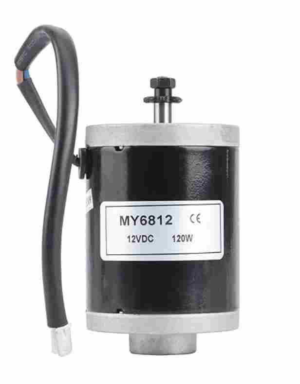
The values we can find as a result are very high and correspond to fairly expensive motors. We checked the calculations with Luc, and the results seem consistent, so we decided to opt for another type of motor with properties not exactly matching those calculated. For the sake of delivery speed and cost, we opted for MY6812 type electric motors, which are widely used for electric bikes and scooters. These still have good power, are highly developed, so they are inexpensive and can be delivered quickly. Using these motors with a very fast RPM (3500rpm) will, however, require a device to multiply the force exerted by my motor to have enough torque.
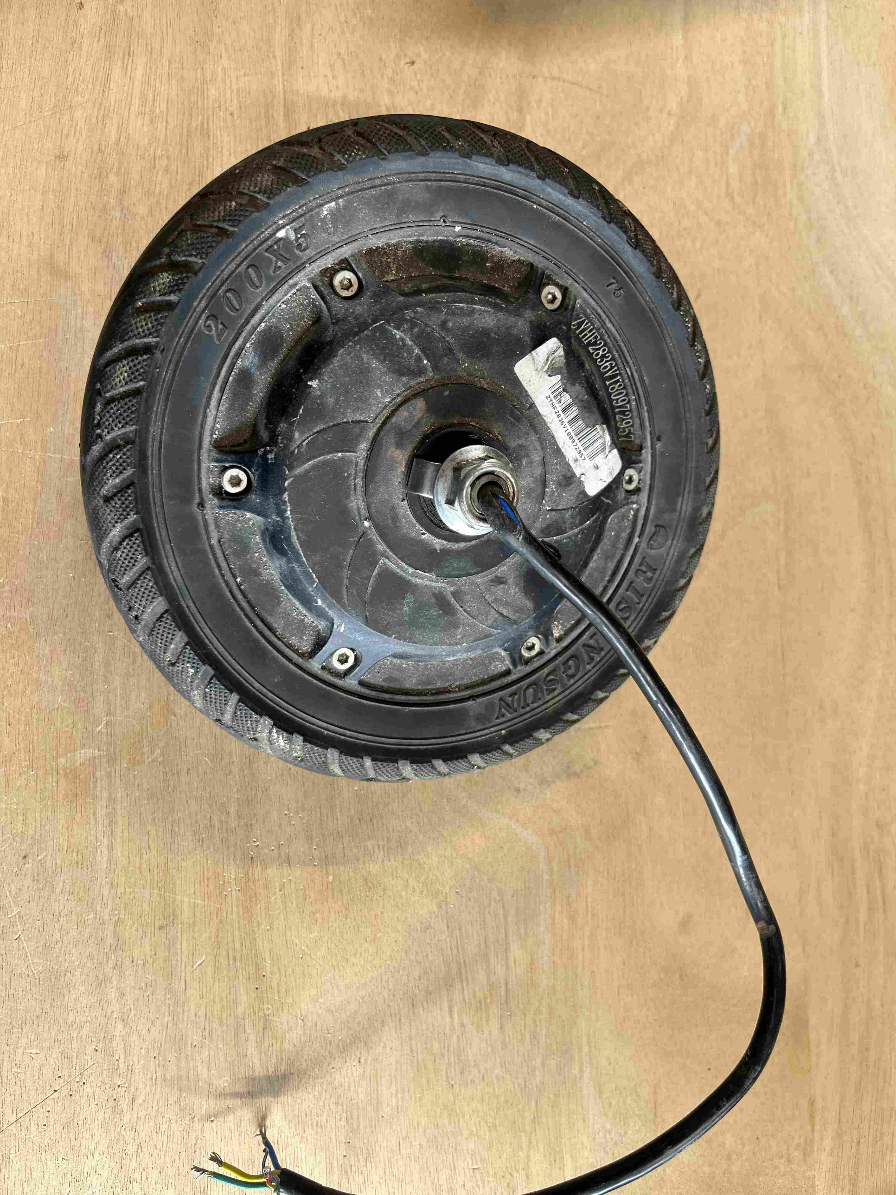
During my motor research, I also tried to test a brushless electric motor from a damaged electric scooter that was at agrilab. I tried to get the brushless motor to work but couldn't, and gave up when I realized that we only had one scooter after all, and that there was no need to waste any more time with this solution.
Battery
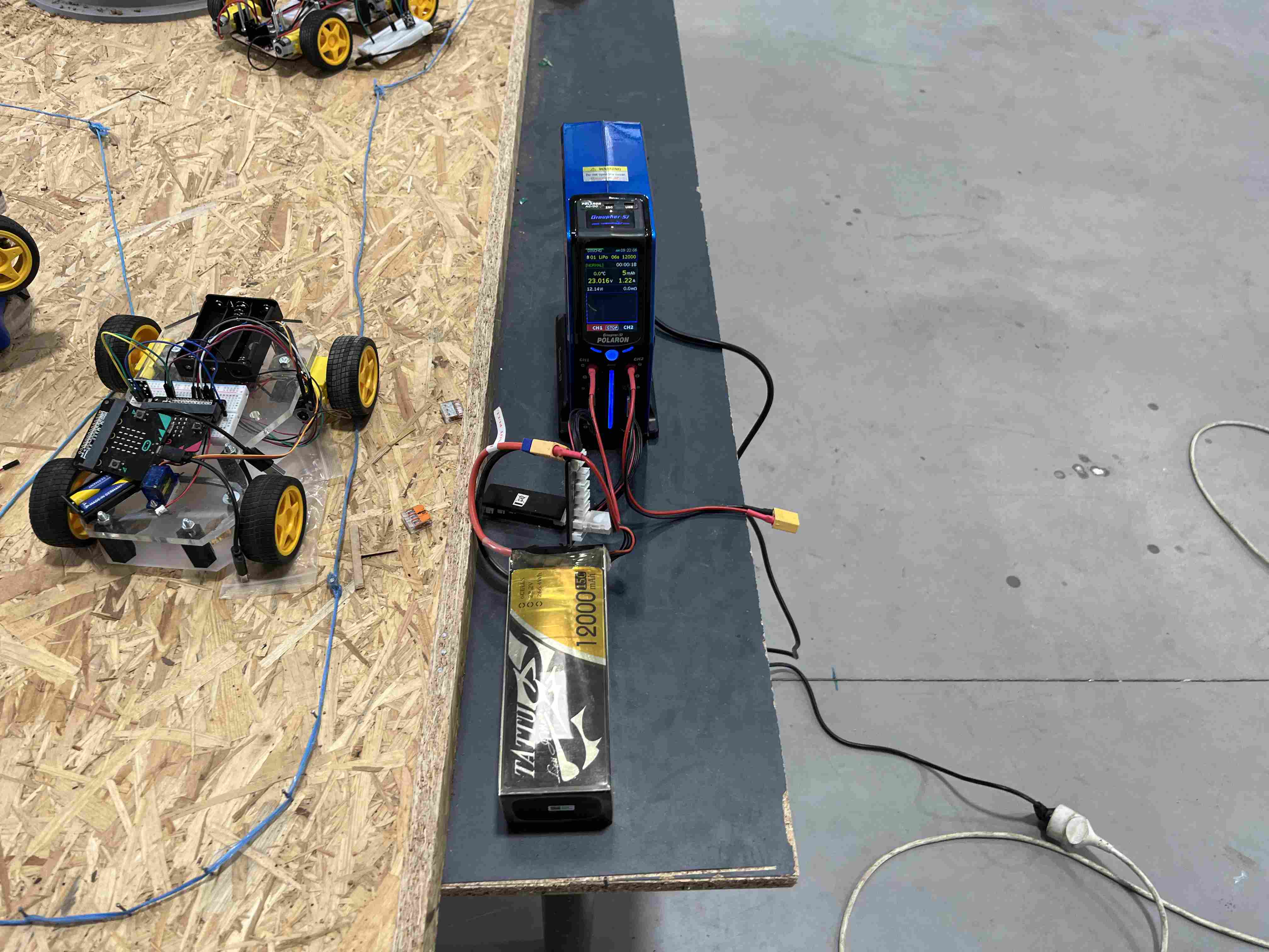
I haven't yet made up my mind about batteries. On the one hand, because prices are extremely high and it's necessary to size their characteristics properly. In order to test, and perhaps as a final solution, I took a drone battery with its charger so that I could use my robot. The drone in which it was housed sputtered, so we first tried charging it to determine whether it was functional or not.
PCB Mounting/ Wire Routing
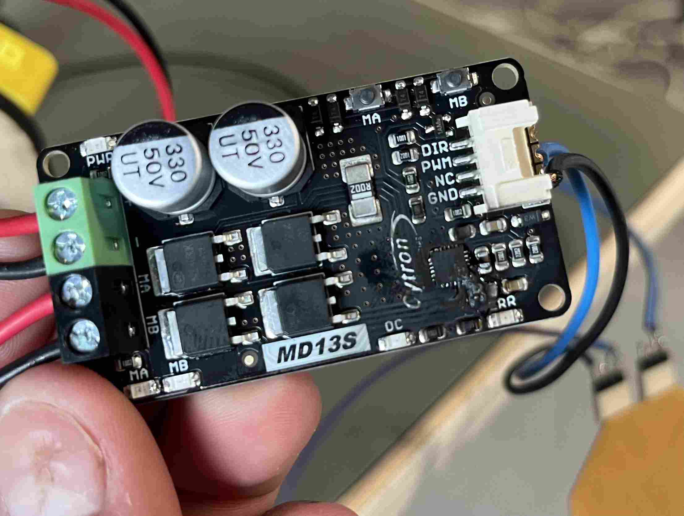
To have the simplest possible circuit, I tried to put female connectors on my PCB so that I could directly connect my drivers to it. I did the same with the UART for the GPS and with the I2C to have a screen. Adding this involves having more tracks on the PCB but simplifies the connection and use of the different elements.
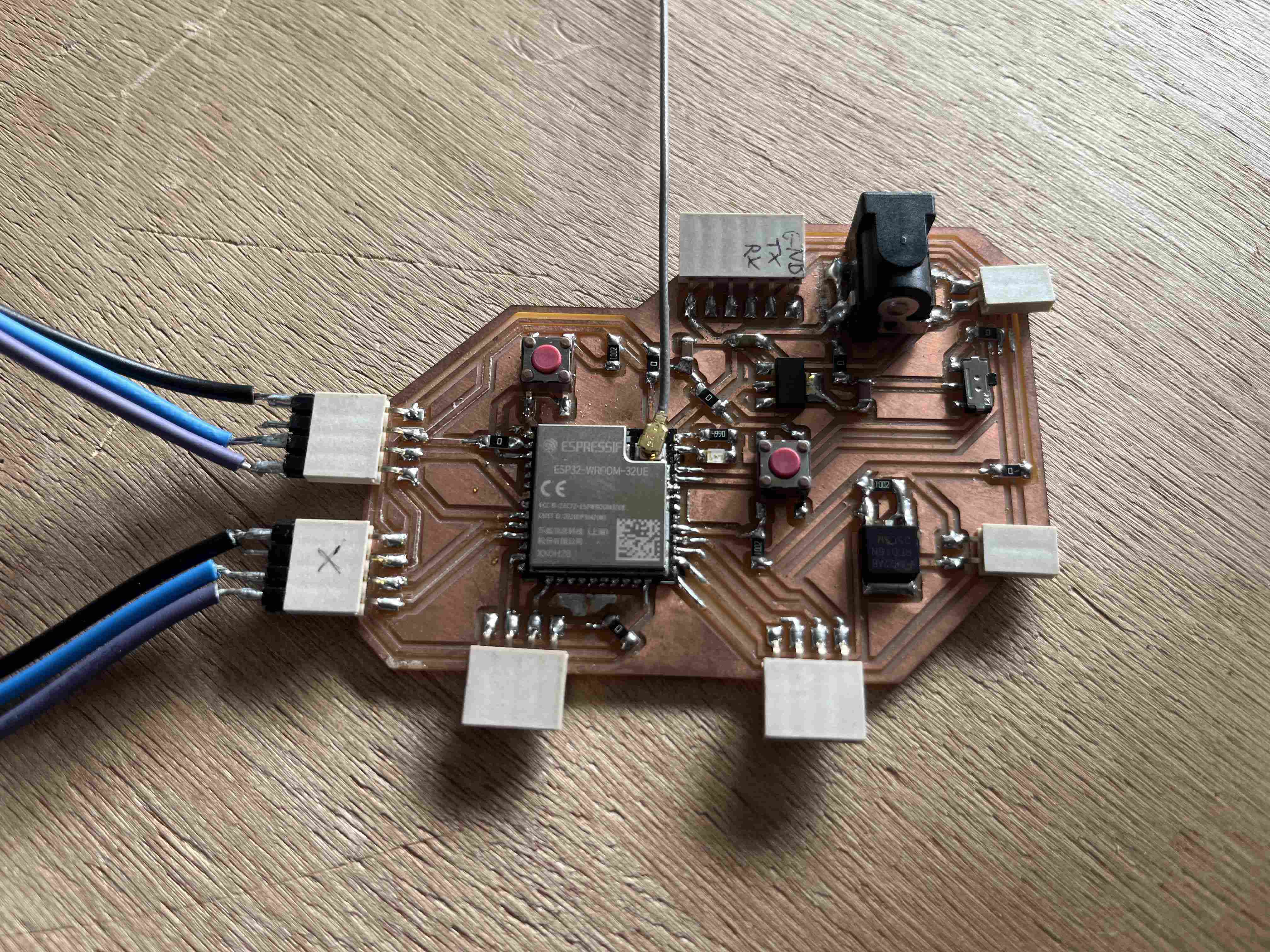
I still have progress to make regarding wire routing. I am well aware that for now the system is not very optimized. As can be seen from my first mock-up, the result is not very satisfactory, and you can see wires everywhere. Of course, the fact that all these components are concentrated in a small space accentuates this disordered effect, but I plan to further optimize this assembly in my final project by using fasteners to properly group the wires together and arranging the cables so that they have the exact length for each component and do not go in all directions.
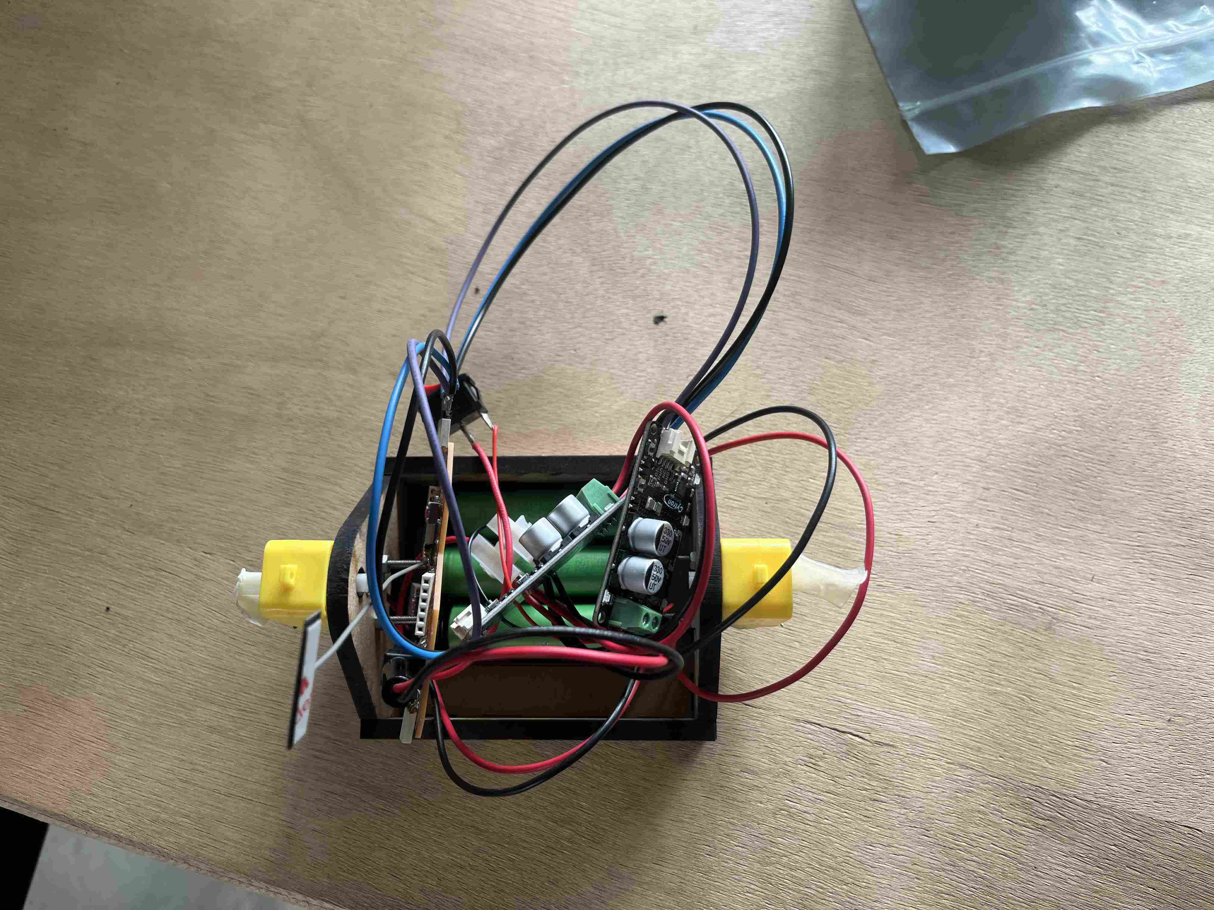
When I tried to test my circuit, all the cables were poorly insulated and touched several places. I probably made a short circuit that burned out one of my two motor drivers.
Of course, from a general point of view, I'm also planning to do a few essential things, such as creating a BOOM to present my project and clearly document the various steps I've taken to get to this end result.