My FabAcademy Final project
Welcome to my final project page, you can get all the information’s about my final project.
Problematic
My objective is to create a system to deal with the problem of crop damage caused by birds, particularly crows. In the days and weeks following sowing, i.e. between emergence and the 9-leaf stage(from Arvalis), corvids go digging in the soil to retrieve plants in order to feed on them. This consumption, multiplied by a very large number of individuals, can cause considerable damage to the plots concerned. If the damage is too extensive, the farmer may have to resow the plot several times. Each resowing entails the purchase of additional seeds, greater fuel consumption, greater wear and tear on equipment and a later planting date, which can quickly become very costly for the farm.

Exemple of crow damages in a crop, from infoagri69
Existing solutions
Regulation, of course, the lower the populations, the less damage there will be. This is achieved either by trapping preserved animals or by shooting them. These methods can be used to limit corvid populations.
Some agronomic levers already exist and involve differences in the technical itineraries for planting, i.e. the way in which the crop is sown.
Agronomic levers(spotifarm):
-Re-press the seedbed well to make it more difficult to pull out the plant.
-Avoid sowing in conditions that are too dry, which makes the soil cloddy and therefore more vulnerable.
-Group sowing with neighbours, for example, to dilute attacks
-Sow wheat at the same time so that crows cannot tell the difference between maize and wheat.
-Deep sowing will make the plant more robust
In addition to all these techniques, which are often not enough, there are also techniques to scare crows away.
Frightening techniques:
-kites in the form of corvid predators that move with the wind
-bazookas that set off very loud gas explosions
-scarecrows to make people look human.
Despite these different techniques, there is still some damage to crops. Corvids are very intelligent animals, able to understand quite quickly that, for example, the scarecrow is not a human and that there is no danger, or that in the case of a bazooka, that the explosion is not dangerous and that they are not afraid of anything.
Even with all these existing solutions, there are still problems of damage to crops, particularly maize, caused by corvids. These devices are all independently effective, but when faced with large crow populations there is still considerable crop damage.
My first idea
To overcome these problems, I'd like to make a robot capable of scaring away crows. I think that by making it mobile, the corvids would take much longer to get used to the presence of the device and would flee the plot for a longer period, or even indefinitely. We could also take into account the robot's ability to emit different types of sound at different frequencies, which would also prevent them from getting used to the robot.
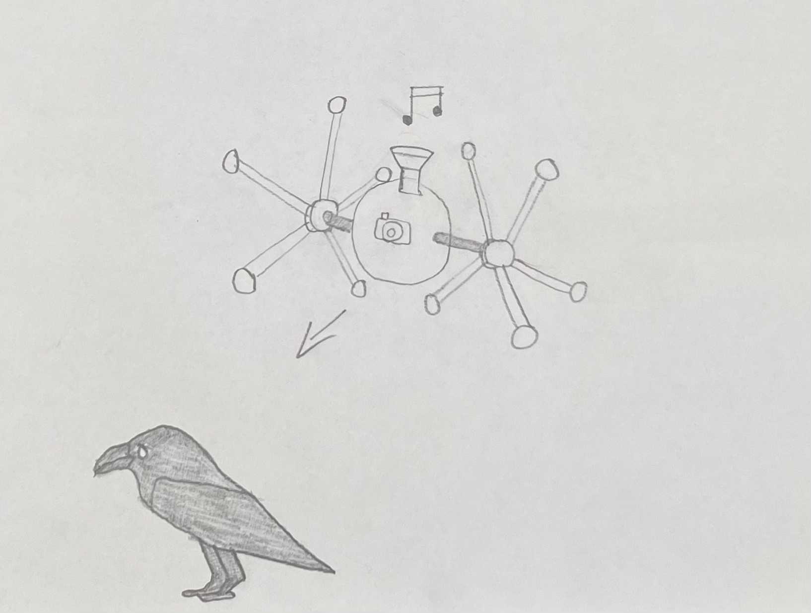
Above you can see a drawing illustrating what the robot could look like and what it could be used for.I've tried to illustrate 'pole wheels' so as not to damage the crop by driving over it.
If I can make a robot that can move within a space, we could then imagine adding satellite guidance functions to enable it to find its way around a plot of land, and so on.
Designing
During the week2, we had to make computer designs, so I decided to make a representation of my robot the way I imagine it. You'll find below the different steps I took to create this design.
3D Modelling
To model in 3D, I chose to use Autodesk's Fusion 360 software. I've already modelled and printed in 3D before and it's already the software I've been using. It's pretty easy to use and offers a large number of functions. To work on the 3D modelling, I chose to model a first version of my final project, which is just an idea and will probably be quite different from the final version.
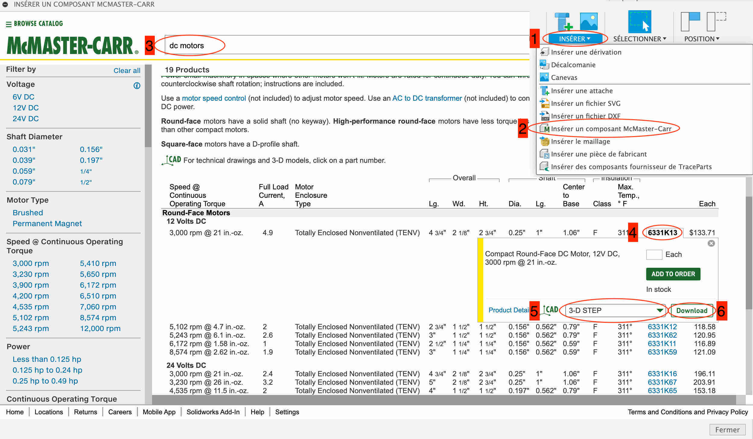
To start my modelling, I based myself on the only elements that I wasn't going to model myself, the electric motors. I used the McMaster-Carr library to get them. It's quite simple, just click on the insert icon at the top right, then click on insert a component from McMaster-Carr. Then look for the component you want, in my case a dc motor. Then select the component you want, taking care not to select the 3D-STEP format before downloading it. The desired component normally appears in our design.
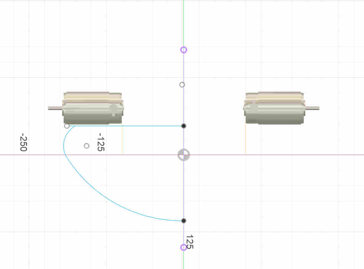
Once I'd positioned my two electric motors, I made a sketch to create the base of the robot, created the shape I wanted on one half and then made a revolution around the Z axis to create my circular shape.
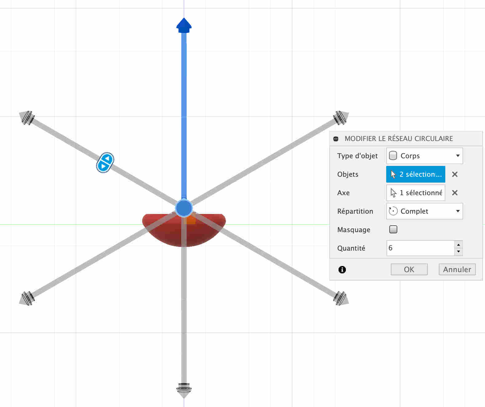
I then made other sketches that I extruded to make the elements of my robot, namely the motor supports and the wheels. As these are wheels with bars, I made a foot and then used the network function to multiply it around the axis of the wheels.
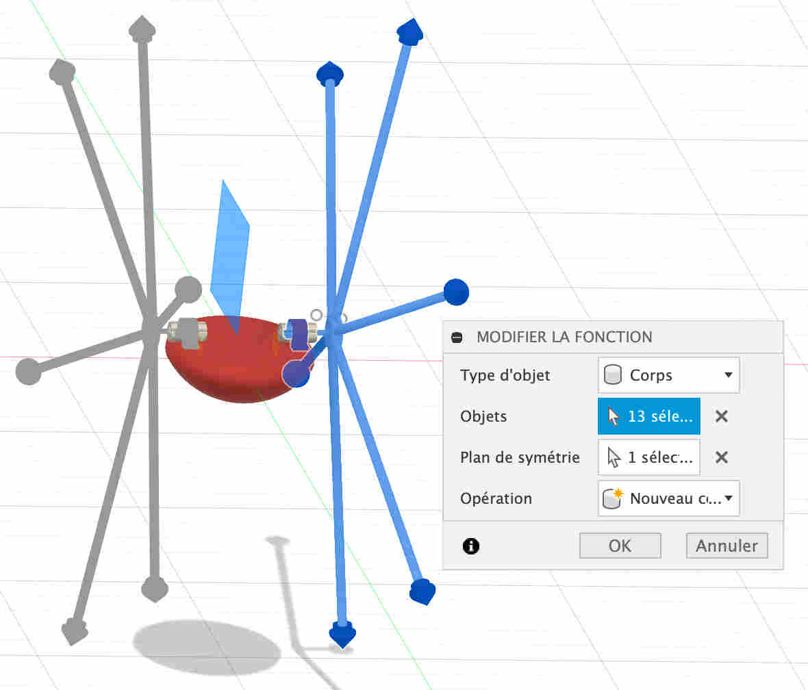
In order to do the same thing on the other side, I had to make a symmetry of these bodies in relation to the Z axis.
Parametric creation
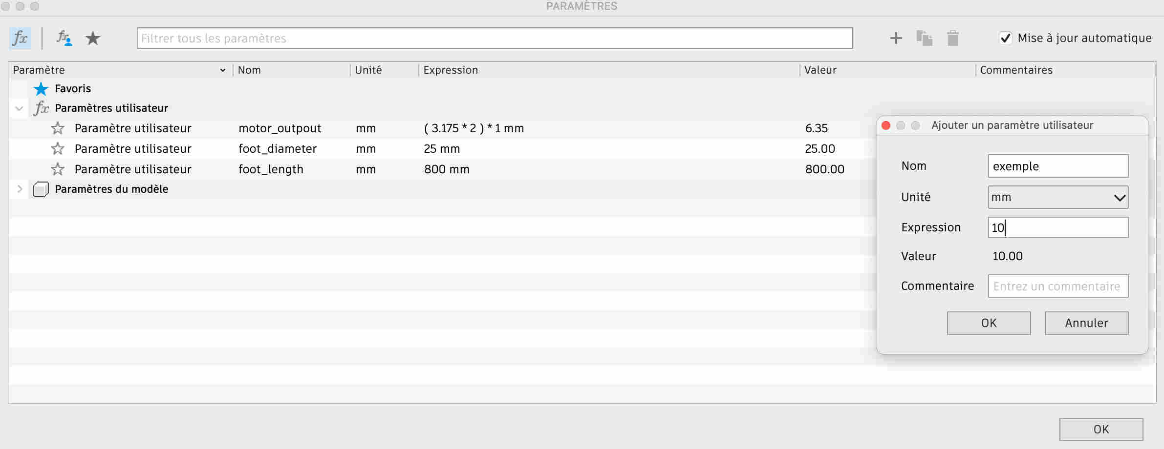
In order to be able to change the values of certain elements of my design, I was able to use parameters that I can still change in order to modify my design. To create parameters, simply go to the edit tab at the top and select the edit parameters option. By clicking on the + you can create a new parameter by entering the name you want to give it and its value. Then, when you want to create a new object, all you have to do is enter the parameter name and change the value. I've only created 3 parameters, the size of the motor output where my wheel fits, the diameter of the bars and their length. I'm very sorry I didn't create more, because when I want to go back, a lot of bodies change place. I should have created one to change the angle of my feet in relation to the support, that would have allowed me to see how the robot would look with different angles.
Creating links
I also made some links so that I could rotate my wheels. To do this I first went to the assemble menu, where I selected the create tool. You then select the two linked faces separately and specify the movement, in my case a revolution. I had a lot of trouble making my wheels turn because I was simply trying to make my motor output shaft coincide with the part that fits on the end, so it was only the motor that was rotating on itself. I had to create a component that included all the components of my wheel to make it work.
Change of materials
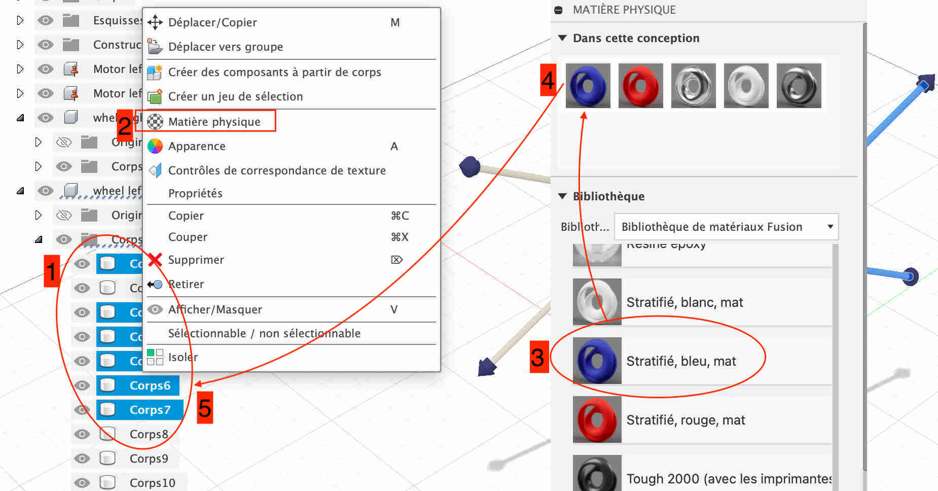
To make my object more realistic and more attractive, I chose to change the materials to give it a different appearance. It's very easy to do, just select the body whose material you want to change, right-click and choose physical material. You then arrive on a page with a multitude of materials, just click on the ones you want at the top of the design materials, and then simply drag the materials onto the bodies you've selected. In my case I've only used plastic because it will be the main component. As for the colour, I wanted a different one for the body of the robot, for the bars and for the spikes, so I chose blue, white and red, the colours of the French flag.
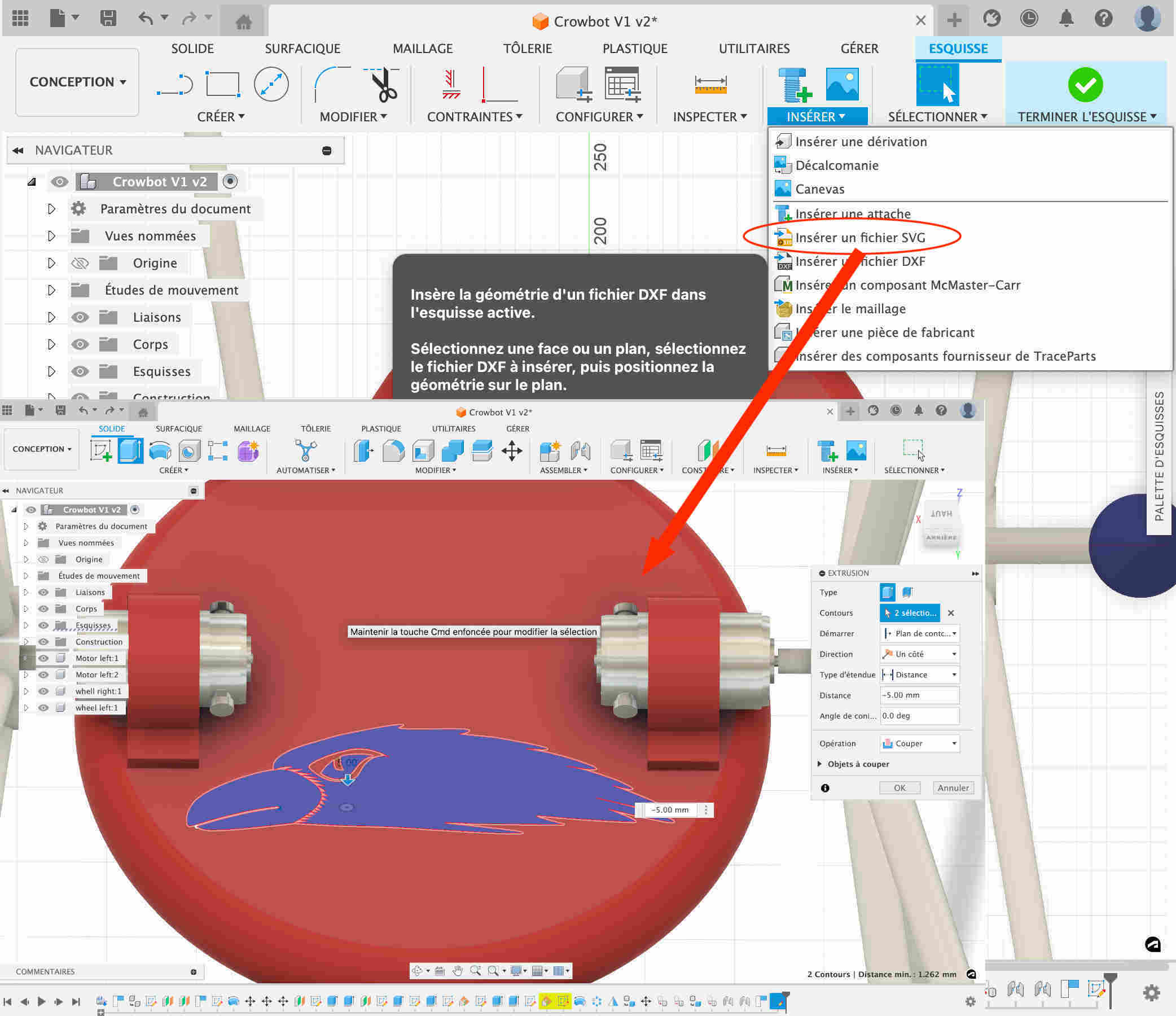
Later, when I'd done my vector creation on Inkscape, I had fun importing it into my design using the insert function, then inserting an svg. Then all you have to do is move the model around and enlarge it as you like. I had a hard time getting this step right because there were two lines that barely touched, which made it look as if the shape wasn't closed. I had to find where the "hole" was in my sketch in order to put a sketch line there. I then extruded the sketch to make it more visible.
Creating a rendering
To make my design more realistic, I did a render to show what it might look like. To do this I went to the Fusion 360 render menu. In the configuration tab, I changed the scene settings. I chose to change the environment by taking the field environment and then I adjusted the various parameters to make the render as realistic as possible. I then went to the render function and it suggested various adaptations before editing the final render. All that's left to do is run it and download it.
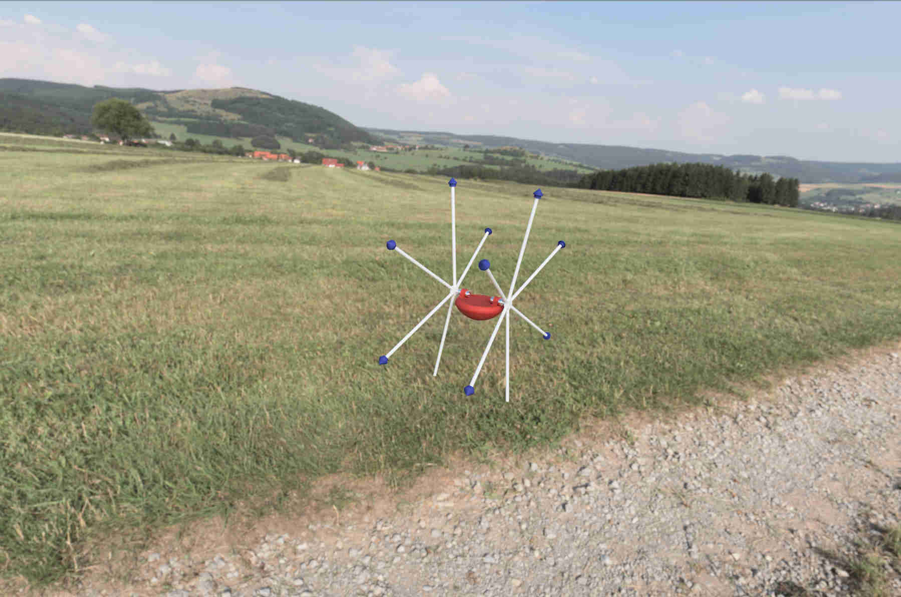
Make an animation
In order to make an animation, I first wanted to use the menu dedicated solely to 360° fusion animations, but there must have been some problem with my design, but I wasn't able to make it move, or else it was the whole robot that was rotating on itself. So I chose to stay in the design menu and activate the movement link for my two wheels. I took the screenshot using the functions on my computer by simply entering Control+Shift+5.
PCB
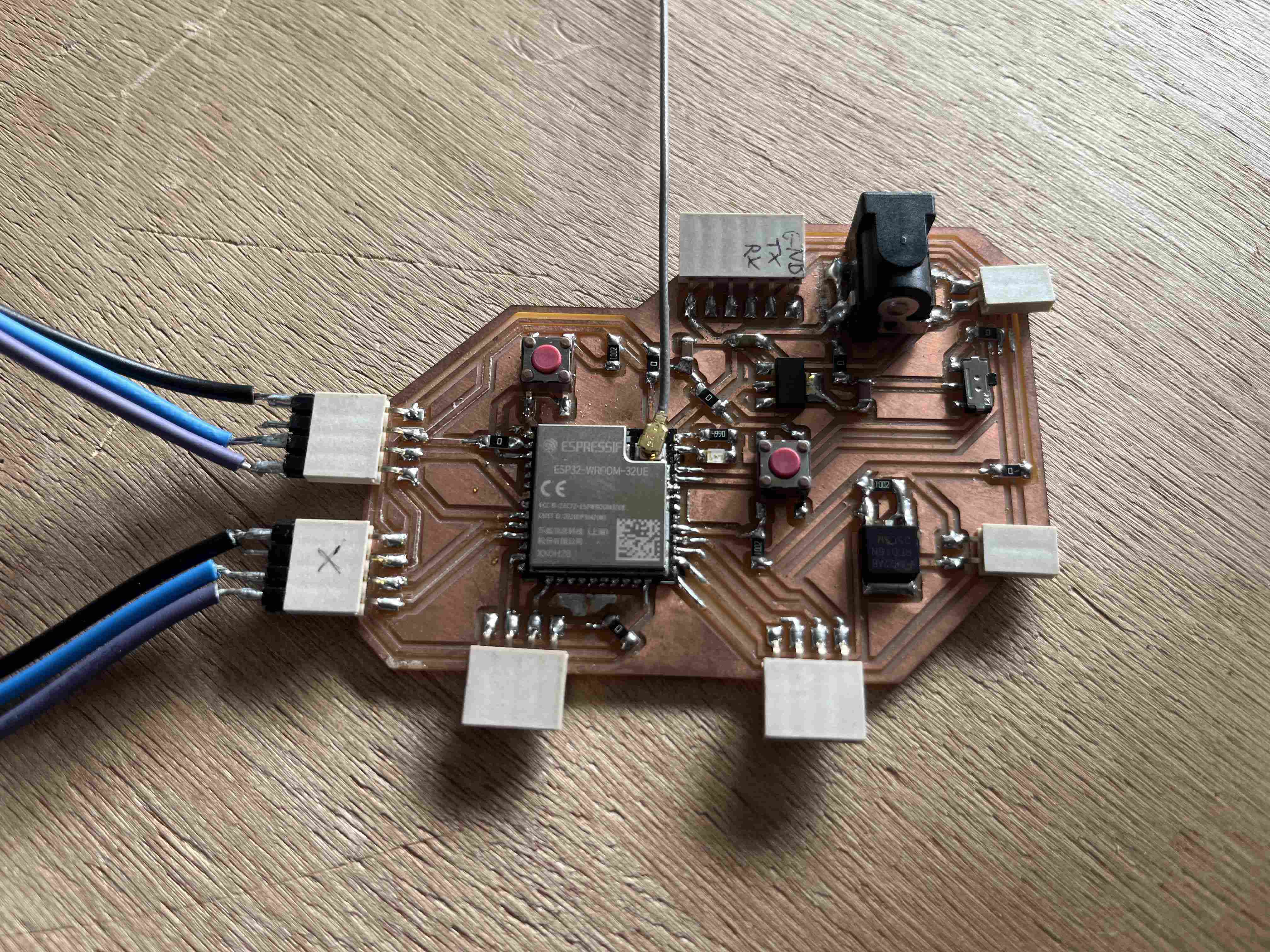
In order to control my robot, I took advantage of the week Electronic design in order to create a first PCB that could be used to control my robot. It's only a first draft, but it was designed on the basis of a ESP32-WROOM-32UE, its first features are the possibility of connecting two motor drivers, an LCD screen and a GPS reception module. Below, you'll find the various stages in the design of this PCB.
Microcontroler
The first thing that had to be done to design this project was to choose a microcontroller, given that I wanted to have wifi and Bluetooth access, so my choice fell on an ESP32. We have various models at Agrilab and I finally chose to use a ESP32-WROOM-32UE. It's quite compact and still has 38 pins, which means it can be used in a variety of ways, so I've obviously got the network functionality. To start working on it, I spent a long time reading the datasheet to determine how I could use each pin and where to connect them.
As I only have a brief knowledge of electronics, I used the map below as an example, inspired by this design from Neil, It also has its own power supply via a barrel and a LED. Using this existing board as a support means I already have a functional environment that I can programme easily and that works with the same microncontroller I've chosen to use.
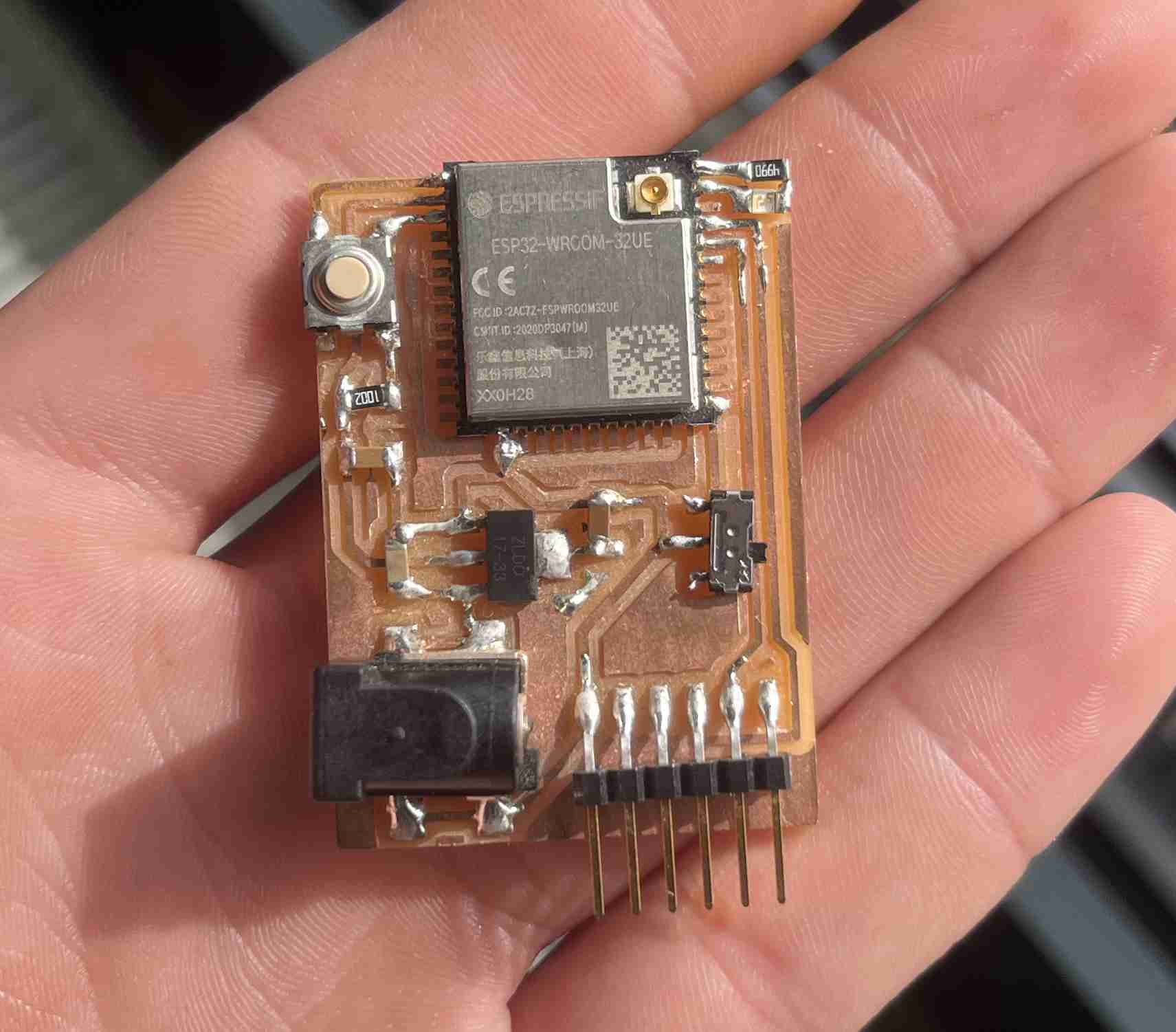
So I decided to create a new circuit based on this example, to which I added 4-pin header pins for different uses:
-2 to control my motor drivers with pins and power supply
-One to receive GPS data with the power supply as well as RX and TX pins
-An I2C output so I can plug in a screen if I want to.
In addition to these outputs, I've added an extra LED and a button
To program this board, I adjusted the RX and TX pins so that it could be programmed using the Quentorres
Kicad
To design this circuit, I used Kicad which is open source software for designing electronic circuits. To get to grips with the software, we had a workshop to learn how to use it on Thursday so that we could master it and reproduce our own circuit. To practise, we tried to reproduce the SAMDino
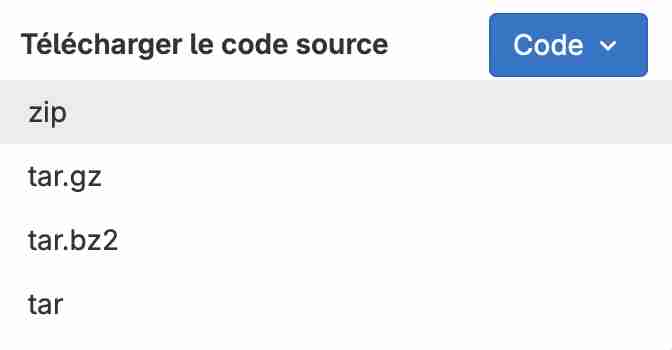
Before you even start, it's a good idea to download the Kicad of the Fabacademy which is made up of a number of extremely useful components. To download it, simply click on code then download the zip file
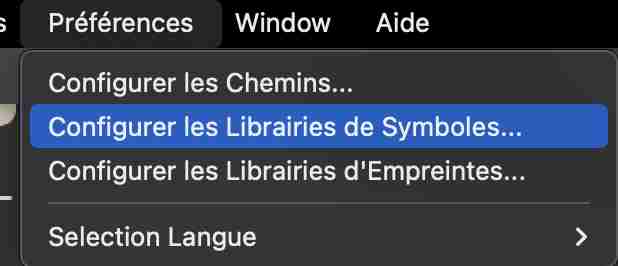
Once the library has been downloaded, you can launch kicad. In the preferences menu, select configure symbol libraries. A new window will open in which you can click on + to add a library, we'll give it a nickname and then look in the unzipped folder for the file fab.kicad_sym, we will then do the same process for the footprints by searching for the file fab.pretty, we can then validate again and use our libraries.
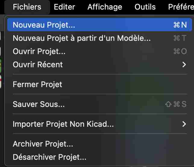
You can then go to the file tab and create a new project that you can name and put in the desired location.
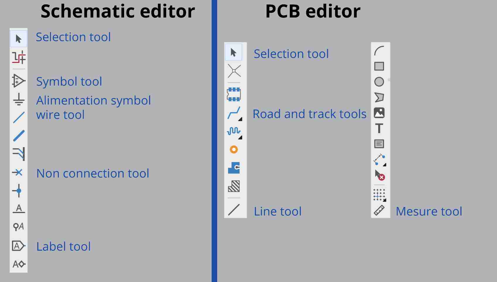
Below is a presentation of the various tools available, including those for the schematic editor and the PCB editor.
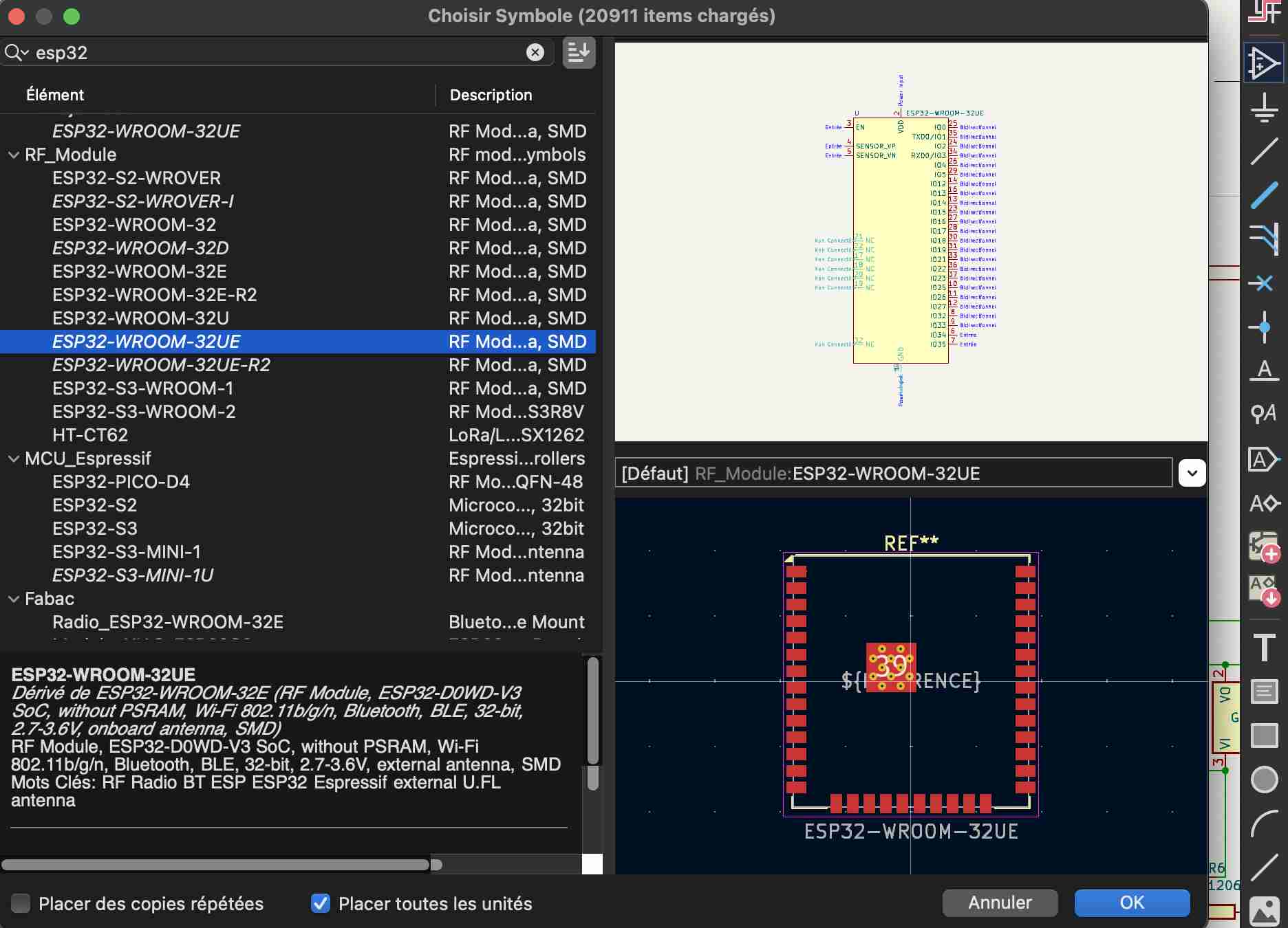
Once the project has been created, you can go to the schematic editor to start creating your circuit. You can start by using the add symbol tool on the right to search for the different components you want to add, for example here my ESP32-WROOM-32UE microprocessor, so you can add the different elements you want to put in our circuit by searching for them in the same way. You don't necessarily know which components you want to add to the list, so you need to compare and don't hesitate to consult the datasheets to be sure. For example, in the case of pinheaders, having only used surface elements, I know that this type of component is always followed by the acronym SMD.
The next most common step is to add the power supply symbols, often 5V, 3.5V and a ground. To do this, go to the power supply symbol tool and select the one you want.
Connecting our elements
Once our elements are in place, we can link them in two different ways:
-With labels
-With wires
To connect them with labels, click on the label tool, a window will open where you can name your label, then click on enter and you can place the label where you want it, then copy the label and paste it where you want to place the other component.
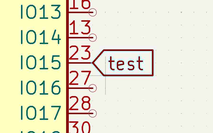
To use the wire tool, simply connect the connections of the elements you want to join together, or use the add wire tool to link the components you want, as shown below.
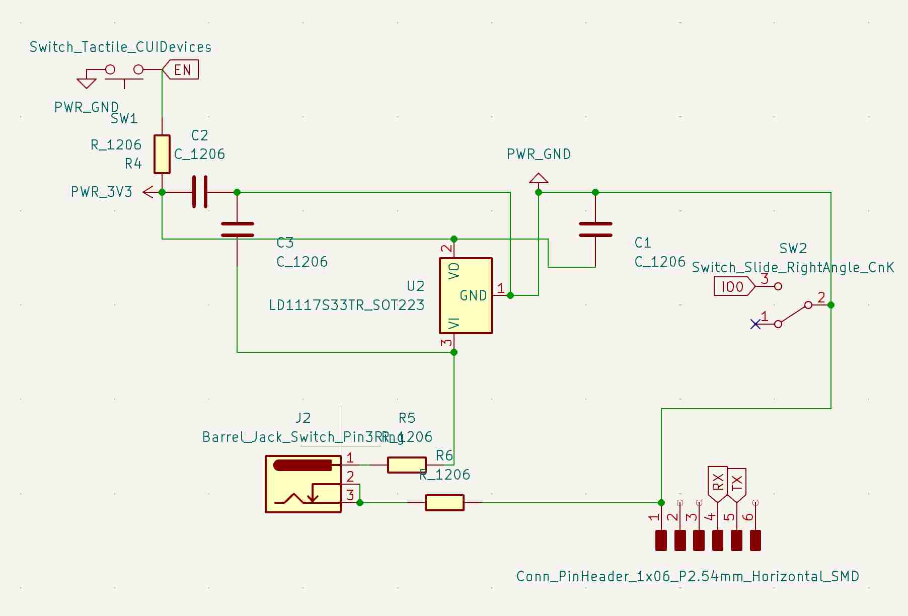
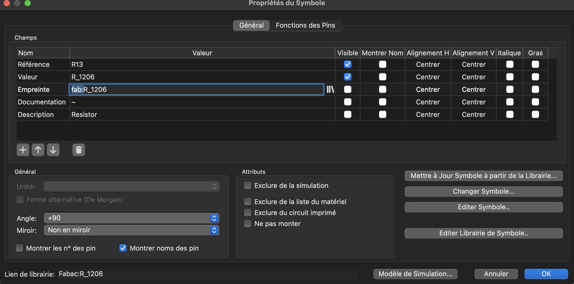
You can then use other tools, such as the no connection tool, to indicate unused pins. To do this, simply use the selection tool and double-click on the component you want to use. A window will open showing the various properties of our component. You can click on the library icon on the footprint line and then go and find the footprint you want. For components in the fabacademy library, simply remove the fab:to find the right footprint.
Once you've changed all your fingerprints, you can click on the function at the top of the screen. Open the PCB in the PCB editor which will open up our PCB editor
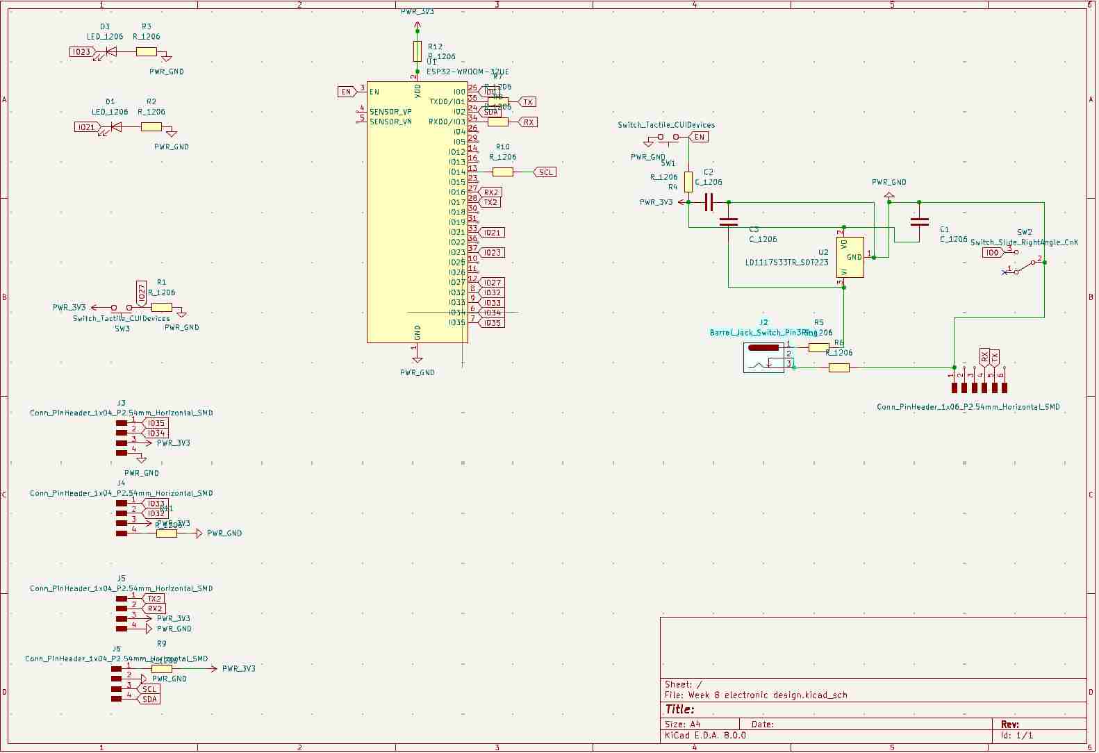
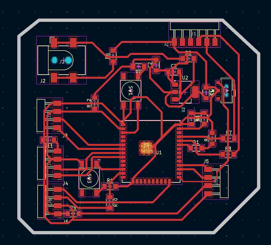
Once in the pcb editor, we can place our components on either side so that the paths can be made without too many problems, i.e. without crossing each other and trying to take up as little space as possible, bearing in mind that the tighter the components, the more complicated they will be to solder, and don't forget to take into account the thickness of the tracks.
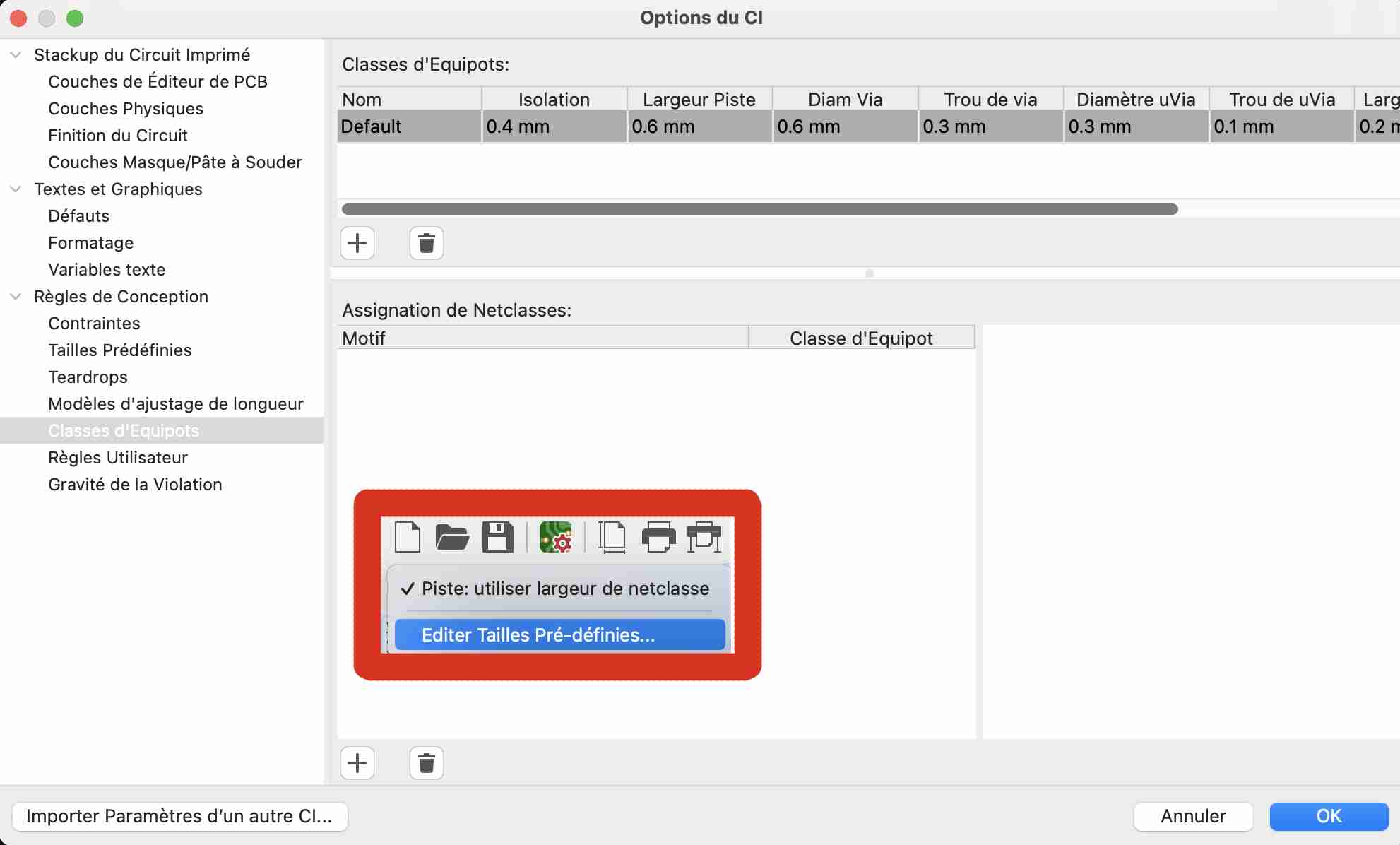
When all the components are positioned correctly and you can see little or no blue lines crossing each other, you can start adding the tracks. We're going to make sure that we draw the tracks so that we have the simplest possible chmins, so we use the track route tool on the right-hand wheel. To modify the characteristics of my tracks I went to the Edit Preset Sizes tool and then to the Equipotential Class where I modified two main values. Firstly, I increased the insulation to 0.4mm and the track width to 0.6mm. This step is essential, firstly because the milling cutters we usually use are 0.4mm, so it's essential to leave at least the space of one milling cutter between two tracks so as not to mill the roads. The wider tracks allow better current flow and heat dissipation. The esp32 is a microcontroller that requires a lot of current, so it's essential to have tracks that let more current through.
Once all our components and tracks are in place, we can draw the outline of our circuit. To do this I went to a different layer in my case user1 and I used the line-drawing tool to draw the outline of my circuit, taking care to draw a 1mm line which corresponds to the diameter of the milling cutter we use to cut the outline of our PCBs. Once these steps have been completed, our PCB is ready to be exported for milling. I'm not very happy with my design, I didn't arrange the space on my circuit properly and to compensate for the poor arrangement of the elements, I had to add 9 0Ohm resistors on my circuit to act as a bridge to pass over the wires.
Once all these steps have been completed, we can export our PCB. To do this, go to Files> Export> SVG to open a new window. Then choose the layer you want to export and various parameters such as the page format, etc. Finally, click on Export
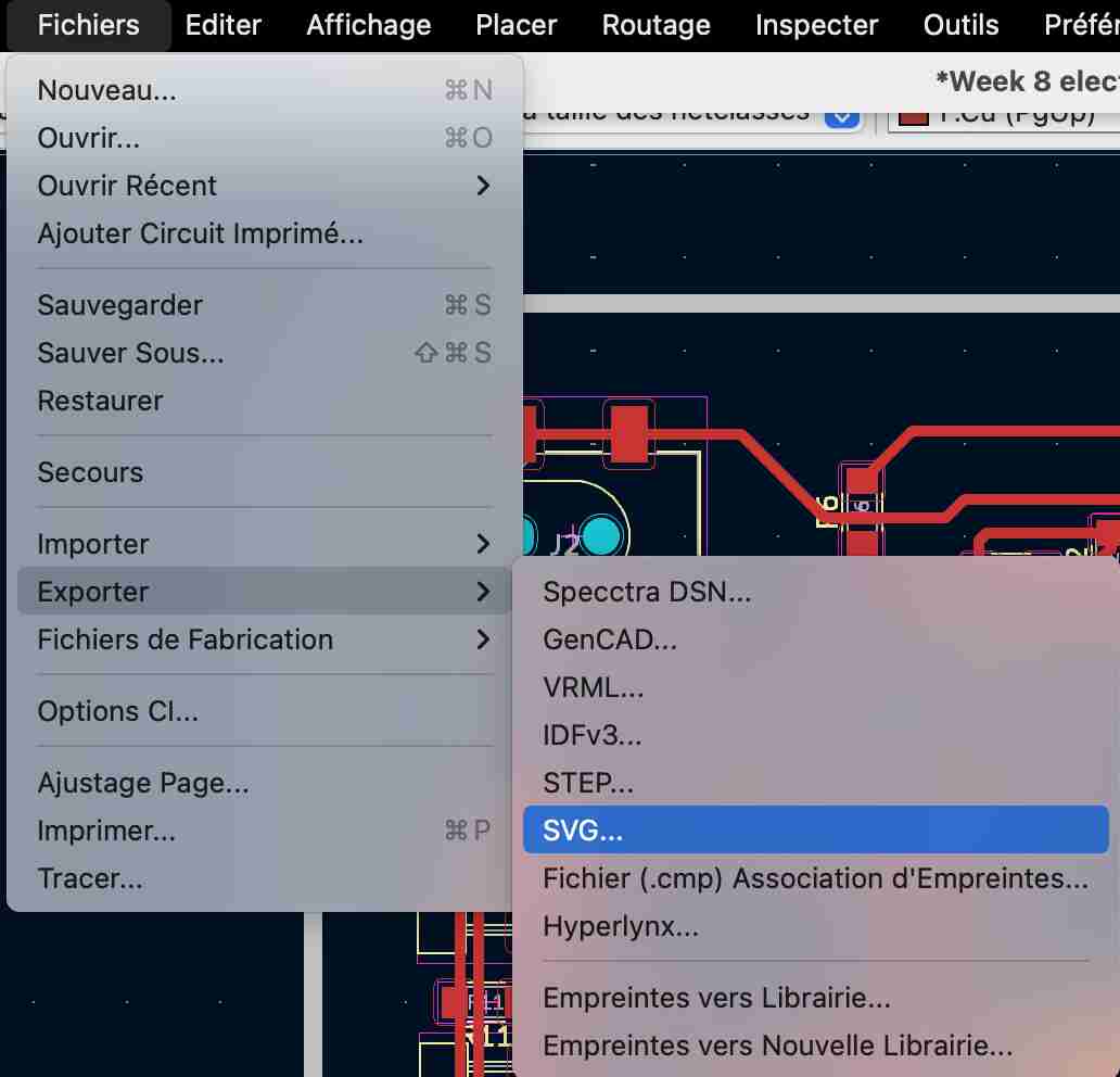
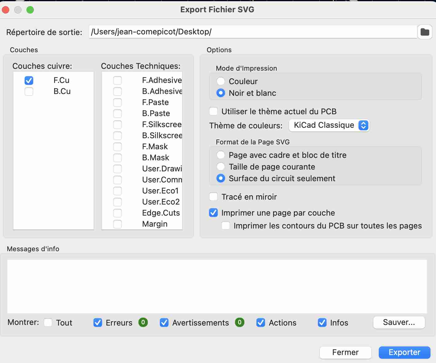
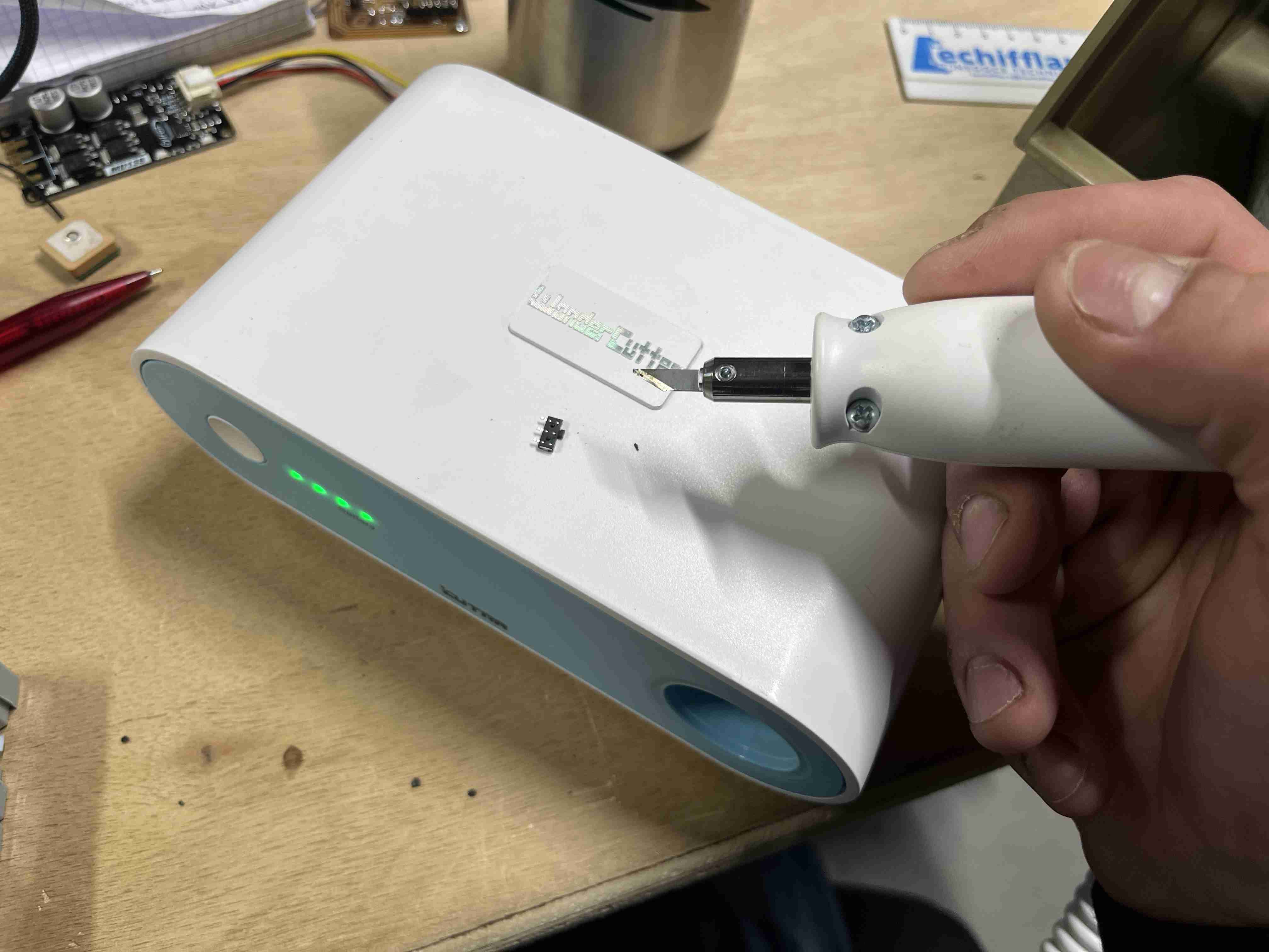
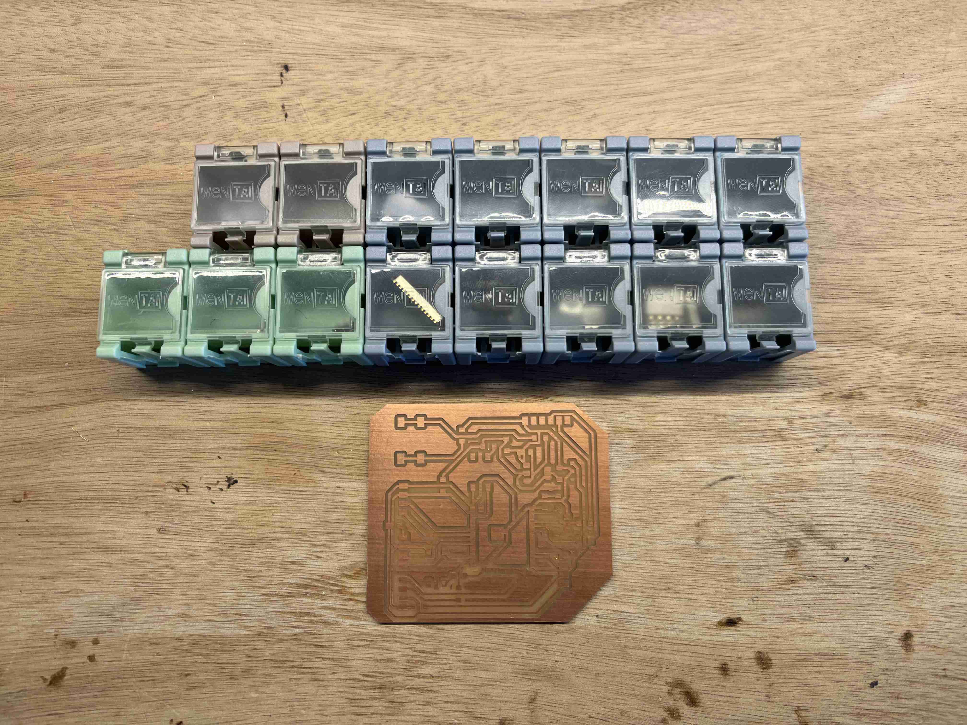
In my case, I exported two layers, the trace layer and the outline layer. I should normally have exported a third layer which corresponded to the holes I needed to make, but I couldn't do it and I was pressed for time. These holes corresponded to the plastic pins that were on the underside of the button and the feed barrel. To save time and avoid having to drill in these places, I used an ultrasonic cutter to cut out the protruding pieces of plastic to create a flat surface.
Milling
To prepare my milling, I used mods again. If you'd like more information on the next steps, you can refer to our week of Electronic production. I used mods again to edit my rml file. During the week of electronic production, we had opened the mill 2D program, during this week I used the mill 2D PCB program. We can then enter our SVG image and the various milling parameters. It's important to remember to reverse when you import the traces so that it doesn't cut the traces but cuts around them.
| Passage | Tool diameter | Cuth depth | Max depth | Offset stepover | Speed |
|---|---|---|---|---|---|
| Traces | 0.4mm | 0.1mm | 0.1mm | 5 | 1.5mm/s |
| Interior | 1mm | 0.4mm | 1.8mm | 2 | 1.5mm/s |
You'll notice that I made two passes to cut my outline, which isn't logical as the diameter of my milling cutter corresponds to the diameter of my outline. I didn't take the time to find out what the problem was and simply made two passes, which doubles the milling time but gives a more satisfactory result. If I'd only left one pass, the milling cutter would have zigzagged and not followed a straight trajectory, which I imagine would have resulted in a poor quality finish. Once the file was ready, I could move on to milling with the Rolland SRM 20. It's also important to reverse the selection when preparing the file, as shown below.
If you want to reproduce this circuit at home, you will find the svg files of the interior and thetraces here
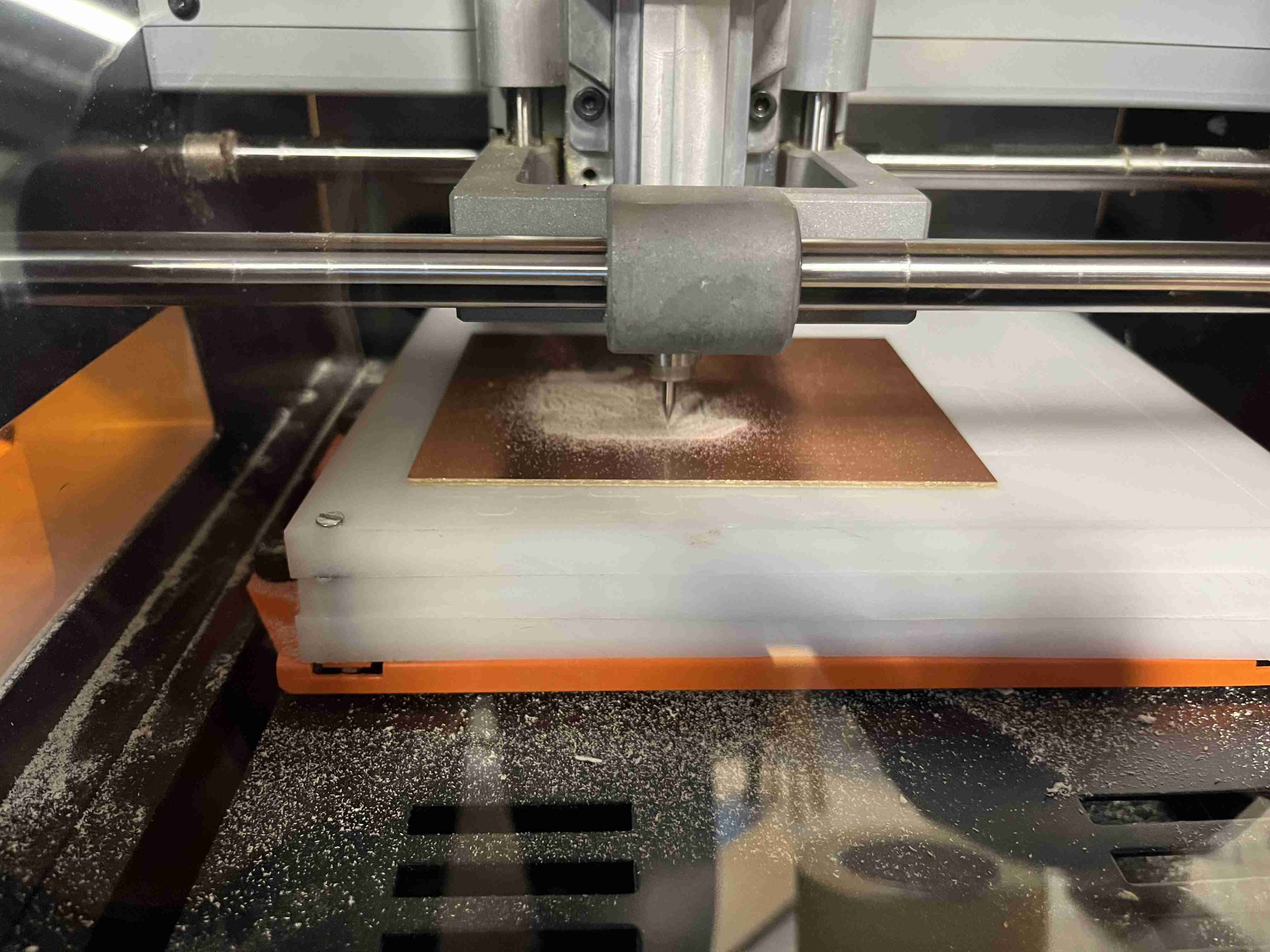
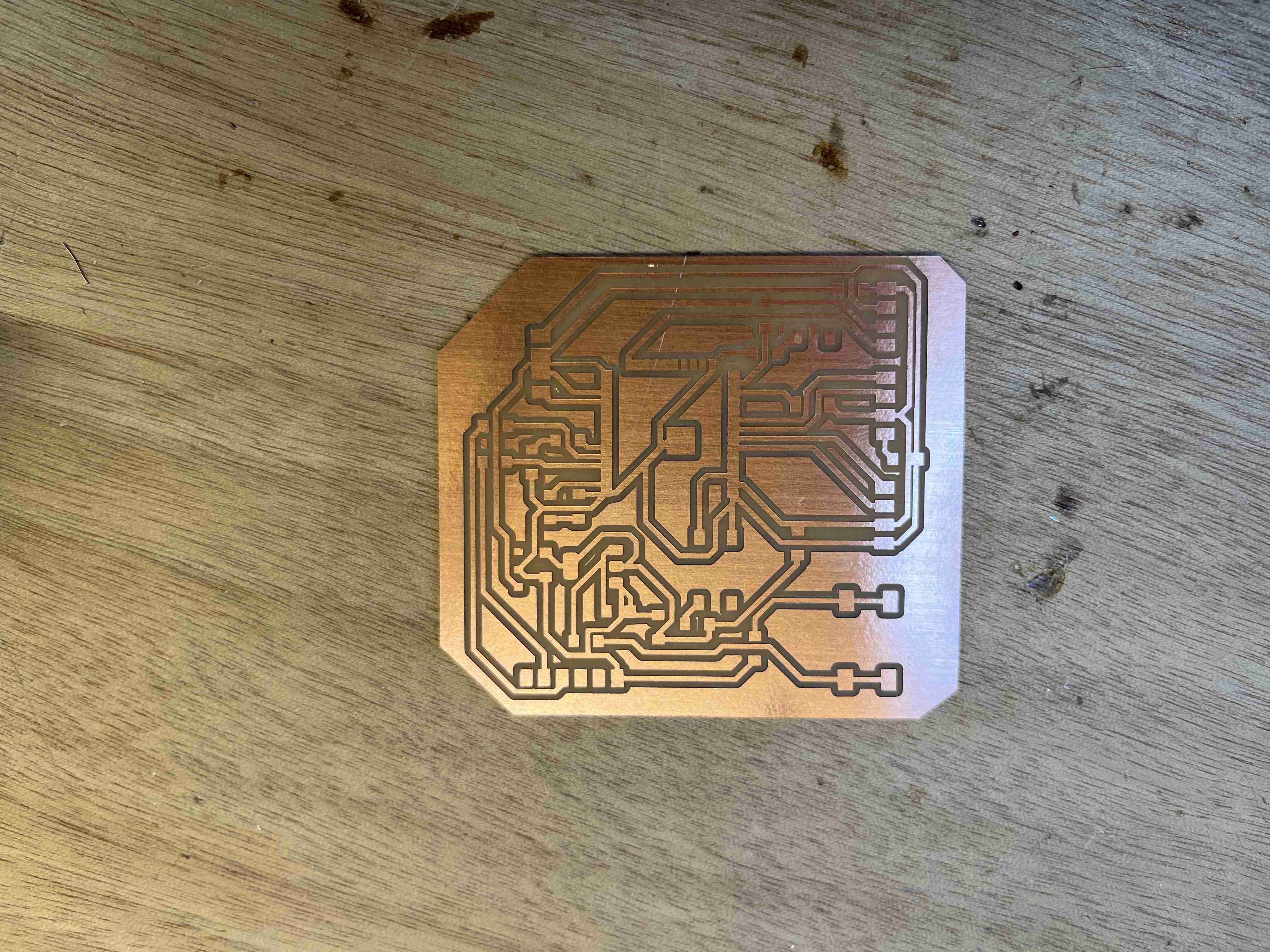
Soldering
Once I'd finished milling, I realised that I'd missed. To do my milling I chose to use a 0.4mm milling cutter, but the distance between the pins on the ESP32-WROOM-32UE is smaller than the diameter of my milling cutter, which meant that the latter didn't mill between the pins. To solve this problem I had to use the ultrasonic cutter again to cut between the pieces of copper that shouldn't have been connected. Once I'd finished re-cutting my tracks, I used the contact tester function on my multimeter to check that I'd done the operation correctly and that there were no connections where there shouldn't be any.
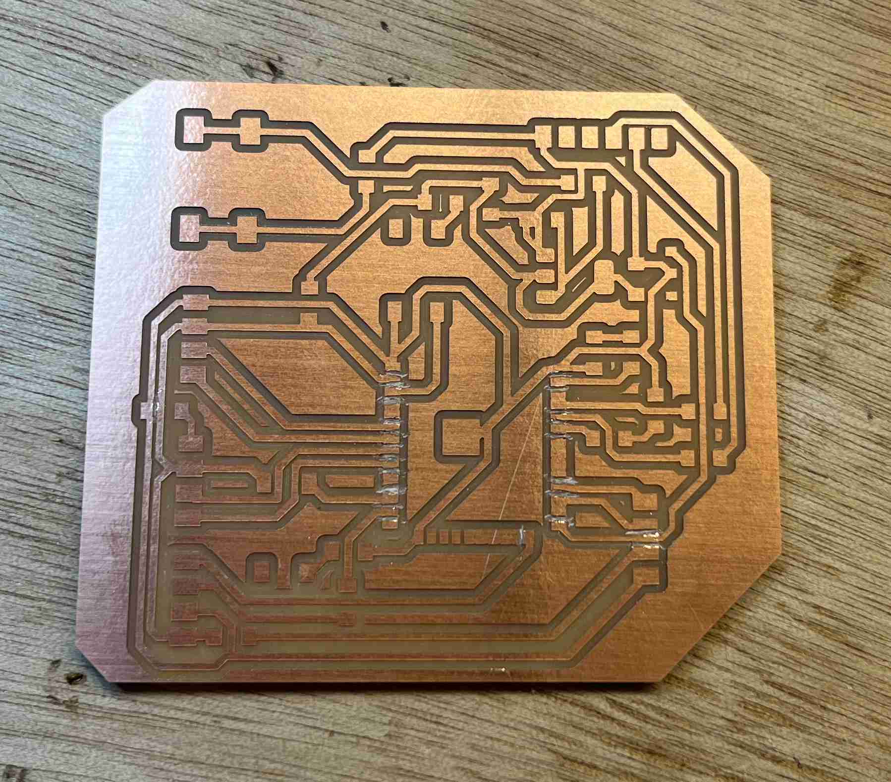
Once all these steps had been completed, I was able to solder all my components onto the circuit.
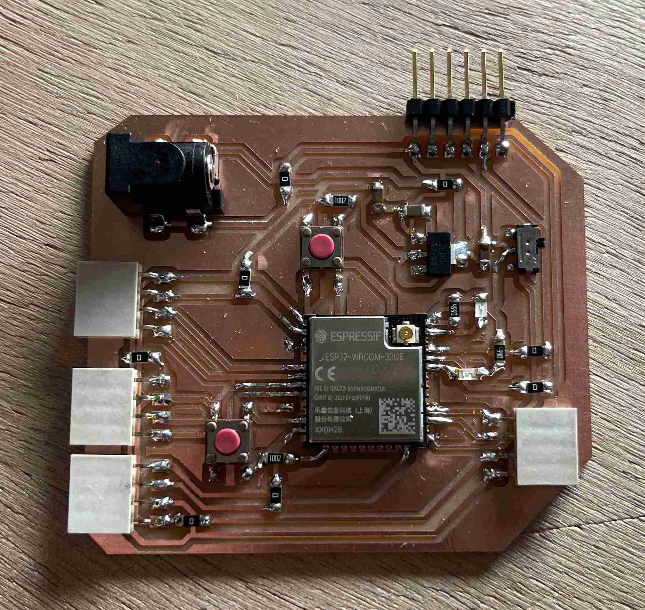
Here is the list of components I used to make this circuit
| Component | Number |
|---|---|
| ESP32-WROOM-32UE-N4 | 1 |
| CONN JACK R/A SMT 5.5X2.1MM | 1 |
| button | 2 |
| interruptor | 1 |
| capacitor 1UF | 2 |
| capacitor 10UF | 1 |
| Pinheader femaleX4 | 4 |
| Pinheader malex6 | 1 |
| Regulator | 1 |
| Resistor 500 Ohm | 2 |
| Resistor 10K Ohm | 2 |
| Resistor 0 Ohm (Jumper) | 8 |
| Led green | 1 |
| Led red | 1 |
Testing
I now have a ready-to-use printed circuit board. It is not easy to upload a code on it, when you have few skills in electronics. I first wanted to use my Quentorres to televise my code on the esp32 but I couldn't manage to put the UF2 firmware on it to use it as a programmer. So I used a programmer made for this purpose that I can connect to my card by simply connecting the GND and RX terminals to the TX.
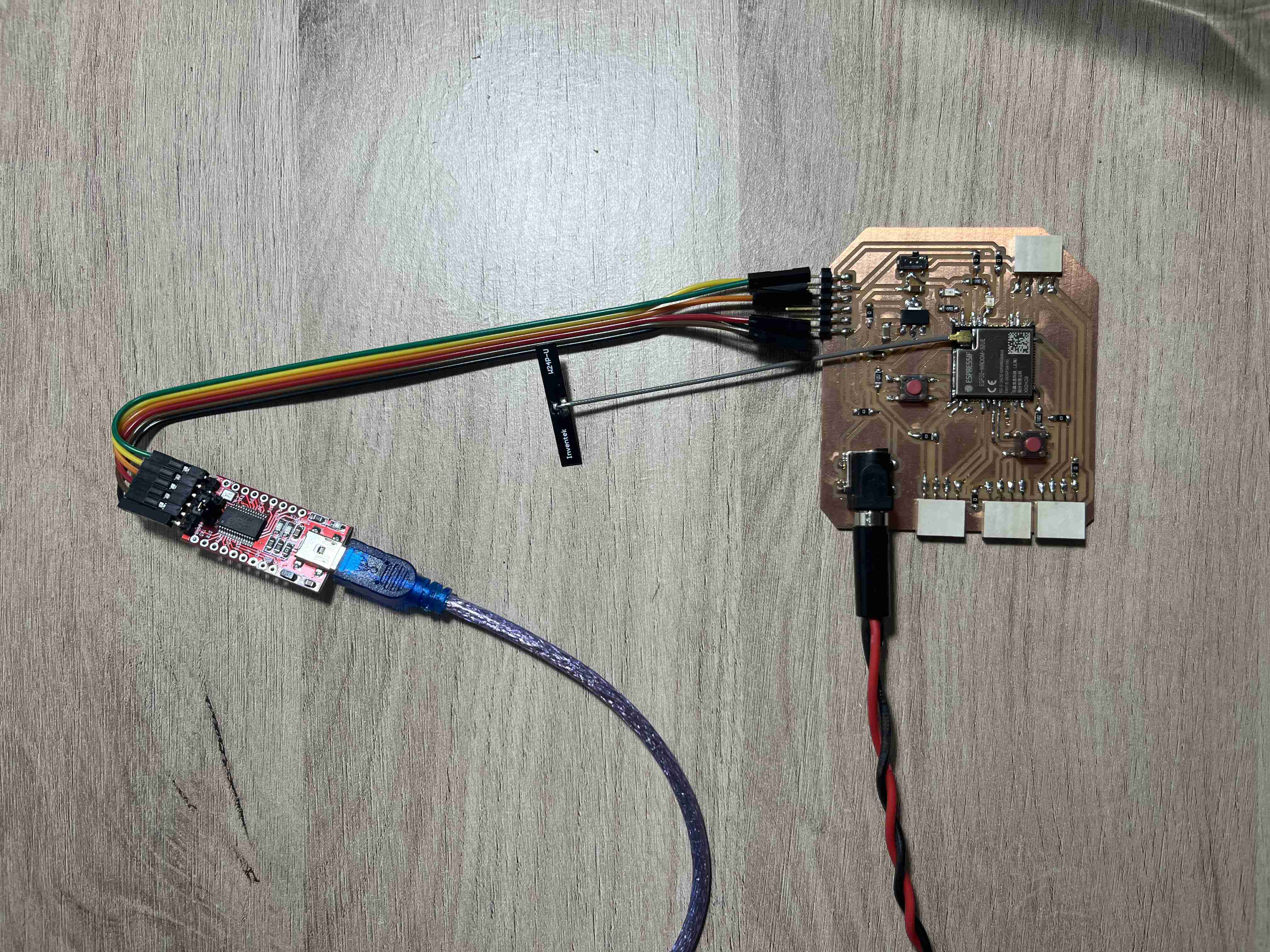
Before even testing our circuit, it is very important to remember to connect an antenna to its location, otherwise the circuit will be burnt out.
Once you are connected to the programmer, you can open the Arduino IDE and go to the preferences. In the additional board manager, we'll add this link https://raw.githubusercontent.com/espressif/arduino-esp32/gh-pages/package_esp32_index.json which refers to the library for using ESP32.
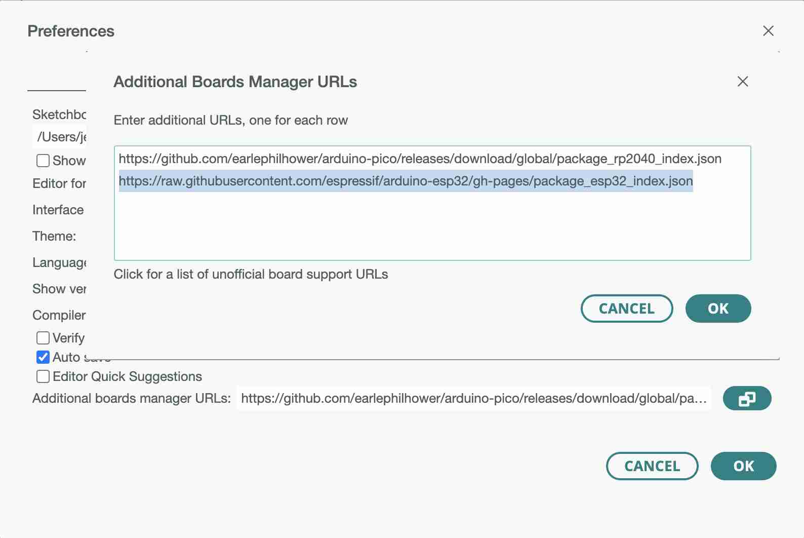
In the cards we're going to use, we'll select the ESP32 Dev Module which corresponds to our microcontroller
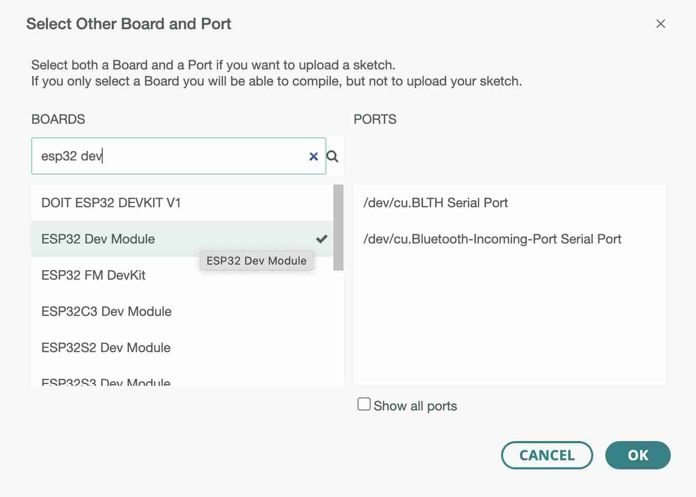
You can then create a program to upload. In my case, I chose to create a blink to test my two LEDs by making them work alternately. You can find the code here
// the setup function runs once when you press reset or power the board
void setup() {
  // initialize digital pin LED_BUILTIN as an output.
  pinMode(23, OUTPUT);//Led red
  pinMode(21, OUTPUT);//Led green

}

// the loop function runs over and over again forever
void loop() {
  digitalWrite(23, HIGH); // turn the LED on
  digitalWrite(21, LOW);  // turn the LED off
  delay(500);                      // wait for a half second
  digitalWrite(23, LOW);    // turn the LED off
  digitalWrite(21, HIGH);   // turn the LED on
  delay(500);                      // wait for a half second
}
As far as uploading is concerned, the process is more complex than with a simple arduino, for example. First of all, the switch has to be lifted to be in download mode. You can then test whether there is a connection by opening the serial monitor. You need to pay attention to the baud rate, which is different from an arduino and is not 9600 but 115 200. If you don't change it, what is displayed on the monitor will be inconsistent. If you press the button and you get the message below, the microcontroller is ready for uploading. and you can upload.


Once the code has been successfully uploaded, you can turn the switch down again and press the button, and the code will run.
I made a major mistake when designing this circuit. I had designed it so that it could power two motor drivers as well as a gps module and an LCD screen. However, I've connected one of my drivers to pins that can't do PWM, so the circuit can't send PWM to the driver and when I try the two motors I'll have to solder wires to connect my driver to a pin that does PWM.
Motor driver
During the week 9, I was able to test the use of motor drivers to control the DC motors that will be used in my robot. You can find my tests below:
To start my week on output, I took the circuit I made during the week electronic design. The aim of this circuit is to control two motors, a screen and a gps module, so I decided to start by testing a DC motor contrôlé lui même pas un motor driver. I started by soldering the connectors that came with the driver, then I made my connections. I connected the driver in the same way as in the diagram below provided in the datasheet.
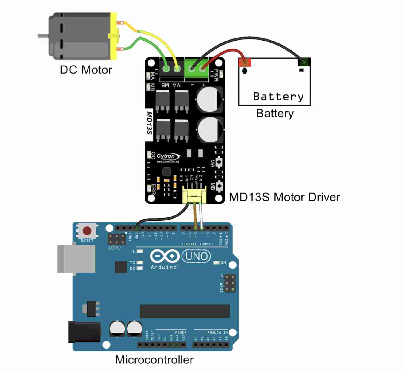
Connect the motor poles to the MA and MB terminals of the driver and supply with a 12V power supply with a + and - on their respective terminals.
As for the driver inputs, I connected 3 of the 4 pins to GND and connected the direction (clockwise/counter-clockwise) to pin33 of my ESP32 and the PWM (used to modulate the speed) to pin 32. Once the connections had been made, I was able to start writing the code
// Define pins for steering control
const int DIR = 33;
//  PWM spindle for speed control
const int PWM_PIN = 32;

void setup() {
  //define the output
  pinMode(DIR, OUTPUT);//direction
  pinMode(PWM_PIN, OUTPUT);//speed
  pinMode(23, OUTPUT);//Led red
  pinMode(21, OUTPUT);//Led green
}

void loop() {
  // Turn the motor clockwise (forward) at medium speed
  digitalWrite(23, HIGH);//led
  digitalWrite(21, LOW);//led
  digitalWrite(DIR, HIGH);
  analogWrite(PWM_PIN, 127); // 50% work cycle (average speed)
  delay(3000); // Wait for 3 seconds

  // Stop the engine
  digitalWrite(23, LOW);//led
  digitalWrite(21, HIGH);//led
  digitalWrite(DIR, LOW);
  analogWrite(PWM_PIN, 0); // Stop PWM
  delay(3000); // Wait for 3 second

  // Running the engine at high speed
  digitalWrite(21, LOW);//led
  digitalWrite(23, HIGH);//led
  digitalWrite(DIR, HIGH);
  analogWrite(PWM_PIN, 255); // Full speed (100% duty cycle)
  delay(3000); // Wait for 3 seconds

  // Stop the engine
  digitalWrite(23, LOW);//led
  digitalWrite(21, HIGH);//led
  digitalWrite(DIR, HIGH);
  analogWrite(PWM_PIN, 0); // Stop PWM
  delay(3000); // Wait for 3 second
}
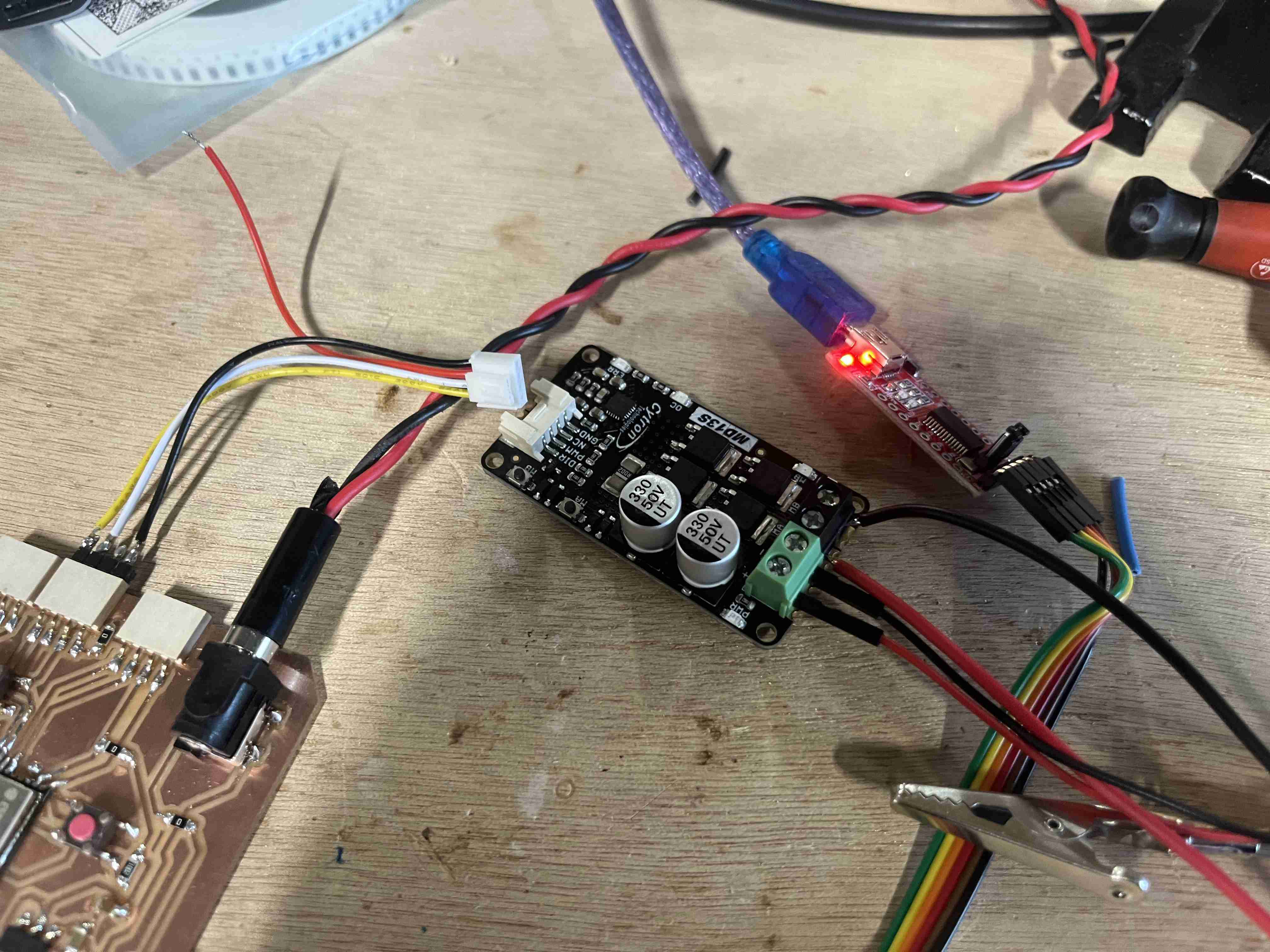
To create this code I mainly used ChatGPT and the driver documentation. I had difficulty programming the drvier, I thought for a long time that it was the fault of my code which was not good. In reality, after searching for a long time, I found myself thanks to this website that of the ESP32 GPIOs, 4 were not capable of PWM. GPIO 34, 35, 36, 39. So I tried again using the pins found in the programme and I managed to get my motor working. However, I was still having problems with false contacts, and if I moved the wires, the motor stopped working. On investigating, I realised that the problem was with the driver's white connectors. So I soldered some wires directly to the driver and managed to get the motor working without a hitch.
GPS
In order to be able to control my robot's movements, it's essential that it has a localization system so that it knows where it is. To this end, I tested the week 11 a GPS module.
The GPS module I was trying was this one you should normally try it with the appropriate software u-center which is not available under IOS, I inquired and saw that we could still read the data even without using the software. In order to make it work I used different GPS documentation with esp32 likethis one and this one.I had abandoned the idea of GPS because I had already lost a lot of time with it.
On Tuesday, Nicolas provided me with a new and different GPS module, it is a module GPS NEO-6M, so I retried all the codes that I had tried and without success, I tried with aESP32 dev kit thinking my PCB was faulty but didn't get better results. I then switched to an Arduino Uno and I was not able to receive anything by trying multiple codes that I could find on the internet and I found this guide . It was by following this last step by step that I managed to capture a signal with an Arduino. In order to connect last, you had to connect the following pins:
| Arduino pin | GPS Module pin |
|---|---|
| GND | GND |
| 5V | 5V |
| 3 | RX |
| 4 | TX |
I first followed the tutorial by entering this code:
/*
 * Rui Santos
 * Complete Project Details http://randomnerdtutorials.com
 */

#include "SoftwareSerial.h"

// The serial connection to the GPS module
SoftwareSerial ss(4, 3);

void setup(){
  Serial.begin(9600);
  ss.begin(9600);
}

void loop(){
  while (ss.available() > 0){
    // get the byte data from the GPS
    byte gpsData = ss.read();
    Serial.write(gpsData);
  }
}
I obtained the following values with this code:
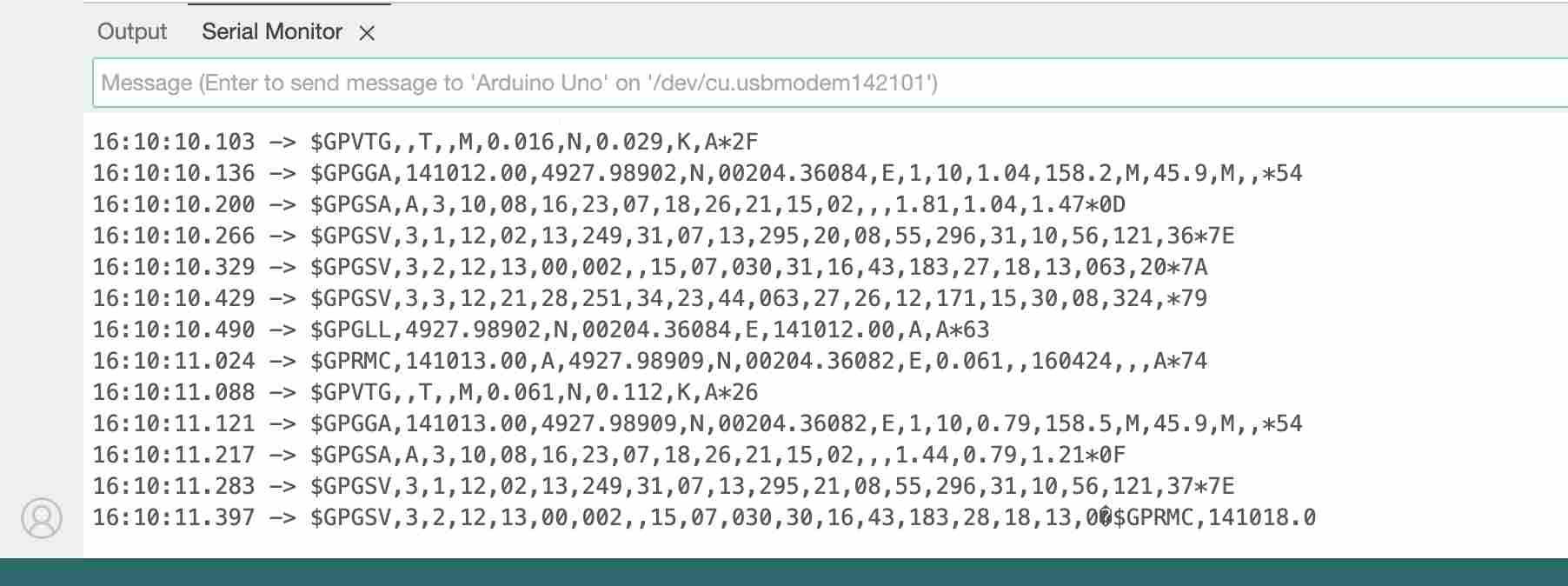
This code is extremely simple, it does not even take into account a library in order to read the data, it simply presents the data provided by the GPS module as it is. While following the tutorial I then downloaded the TinyGPS++ library, I had of course already downloaded it but given my difficulties it was quite simple to follow the tutorial. It is therefore necessary to download the library TinyGPS++. Once the zip file is downloaded, we can unzip it and we obtain a folder named
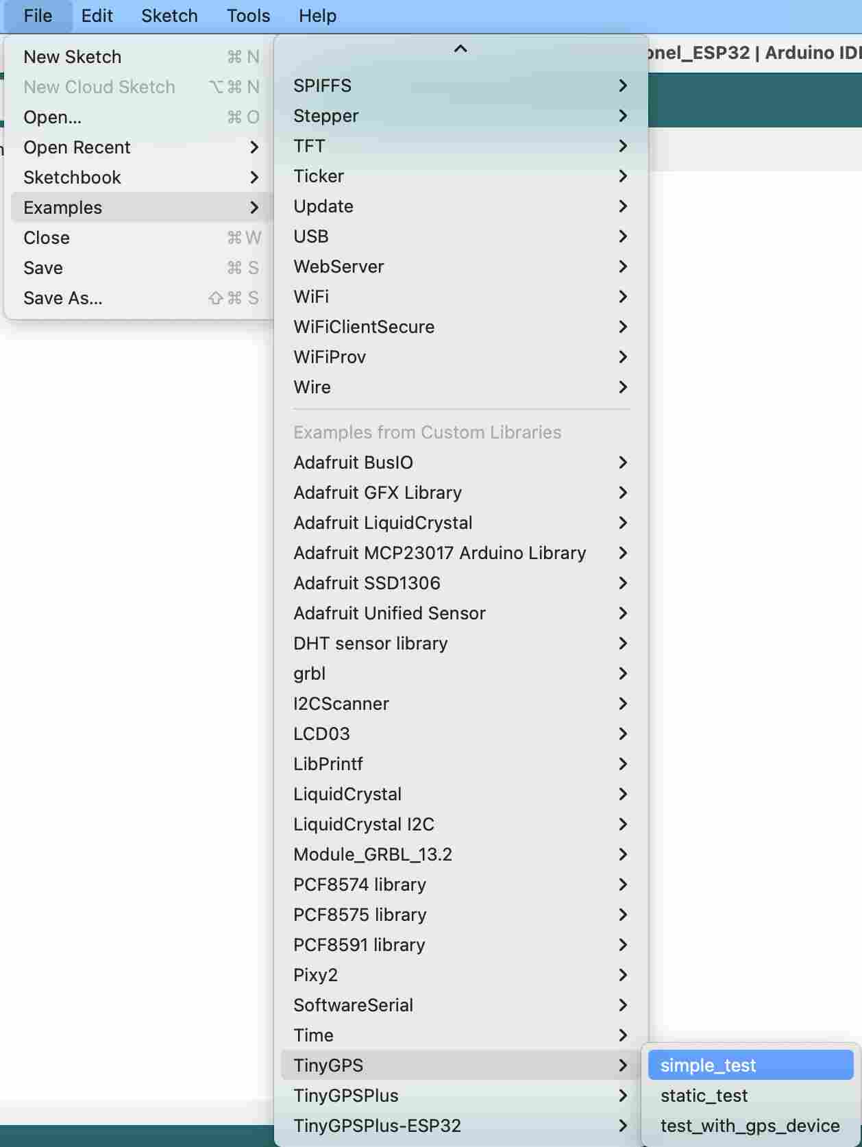
We can then launch our IDE and follow the following path: File > Exemples > TinyGPS > simple_test which will open the test file for us. However, before uploading it, it will be necessary to modify the ss.begin(4800); by ss.begin(9600); on line 16. This modification corresponds to the Baudrate of our module which is different. Once this code was uploaded, I finally managed to read GPS data
I then had to be able to read this data using my ESP32. I modified the original code proposed by the library by replacing the library SoftwareSerial by the libraryHardwareSerial. During the change I also changed the pins which are not the same on the ESP32 and on the Arduino. Following the modifications, the final code that allowed me to read GPS data from the NEO-6M GPS module with my PCB based on an ESP32-Wroom-32UE is as follows:
#include "TinyGPS.h"
#include "HardwareSerial.h"

/* This sample code demonstrates the normal use of a TinyGPS object.
   It requires the use of HardwareSerial, and assumes that you have a
   9600-baud serial GPS device hooked up on pins 16(rx) and 17(tx).
*/

TinyGPS gps;
HardwareSerial gpsSerial(2); // Utilisation du port matériel UART2 de l'ESP32

void setup()
{
  Serial.begin(115200);
  gpsSerial.begin(9600, SERIAL_8N1, 16, 17); // Initialisation du port série pour le GPS

  Serial.print("Simple TinyGPS library v. "); Serial.println(TinyGPS::library_version());
  Serial.println("by Mikal Hart");
  Serial.println();
}

void loop()
{
  bool newData = false;
  unsigned long chars;
  unsigned short sentences, failed;

  // For one second we parse GPS data and report some key values
  for (unsigned long start = millis(); millis() - start < 1000;)
  {
    while (gpsSerial.available())
    {
      char c = gpsSerial.read();
      // Serial.write(c); // uncomment this line if you want to see the GPS data flowing
      if (gps.encode(c)) // Did a new valid sentence come in?
        newData = true;
    }
  }

  if (newData)
  {
    float flat, flon;
    unsigned long age;
    gps.f_get_position(&flat, &flon, &age);
    Serial.print("LAT=");
    Serial.print(flat == TinyGPS::GPS_INVALID_F_ANGLE ? 0.0 : flat, 6);
    Serial.print(" LON=");
    Serial.print(flon == TinyGPS::GPS_INVALID_F_ANGLE ? 0.0 : flon, 6);
    Serial.print(" SAT=");
    Serial.print(gps.satellites() == TinyGPS::GPS_INVALID_SATELLITES ? 0 : gps.satellites());
    Serial.print(" PREC=");
    Serial.print(gps.hdop() == TinyGPS::GPS_INVALID_HDOP ? 0 : gps.hdop());
  }

  gps.stats(&chars, &sentences, &failed);
  Serial.print(" CHARS=");
  Serial.print(chars);
  Serial.print(" SENTENCES=");
  Serial.print(sentences);
  Serial.print(" CSUM ERR=");
  Serial.println(failed);
  if (chars == 0)
    Serial.println("** No characters received from GPS: check wiring **");
}
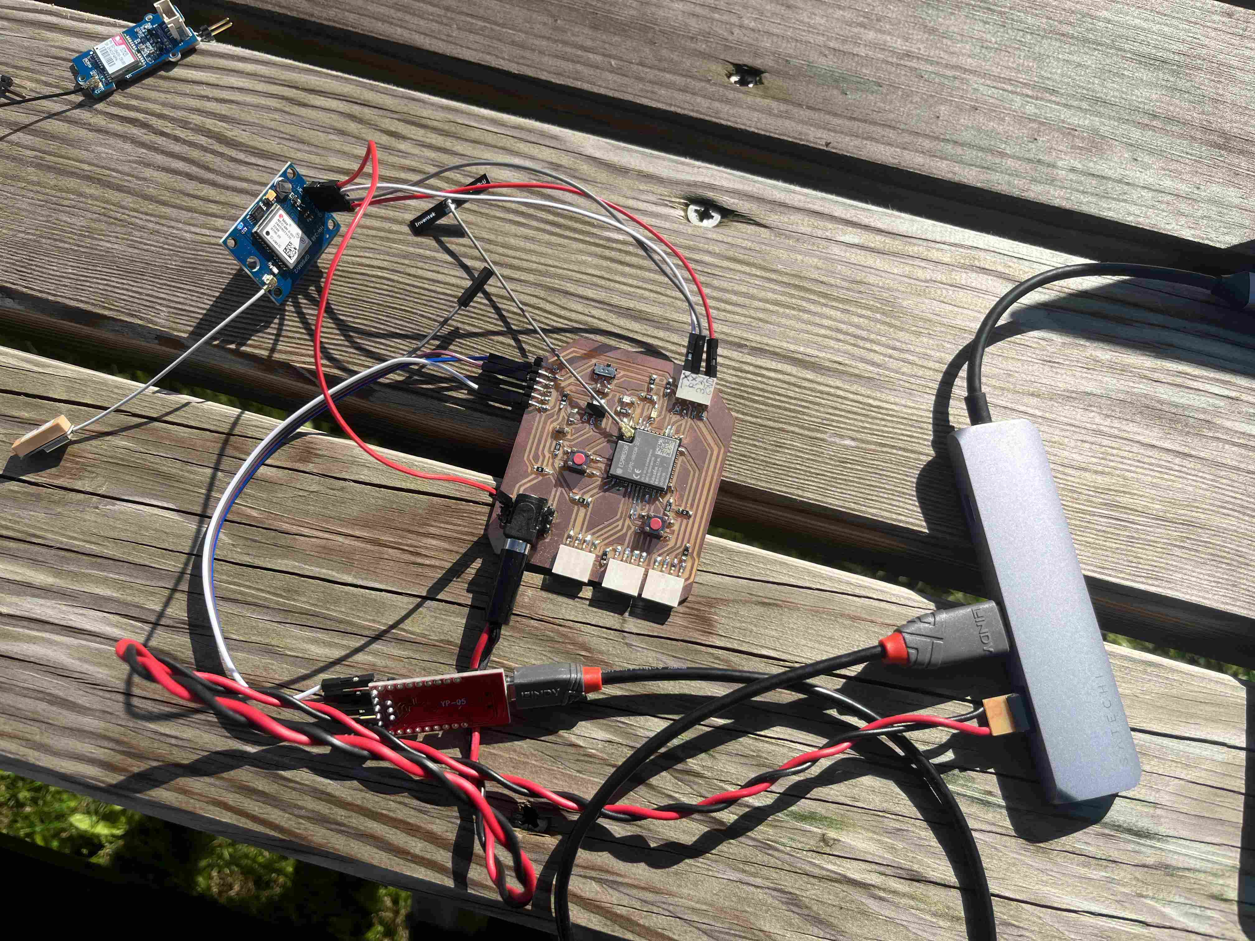
In order to put my code, I connected the pins in the following way.
| Arduino pin | GPS Module pin |
|---|---|
| GND | GND |
| 5V | 5V |
| 16 | RX |
| 17 | TX |
I was then able to put the code on my ESP32 and read the data, and finally after two days of trying to get the GPS to work, I succeeded and got the following values with this setup:

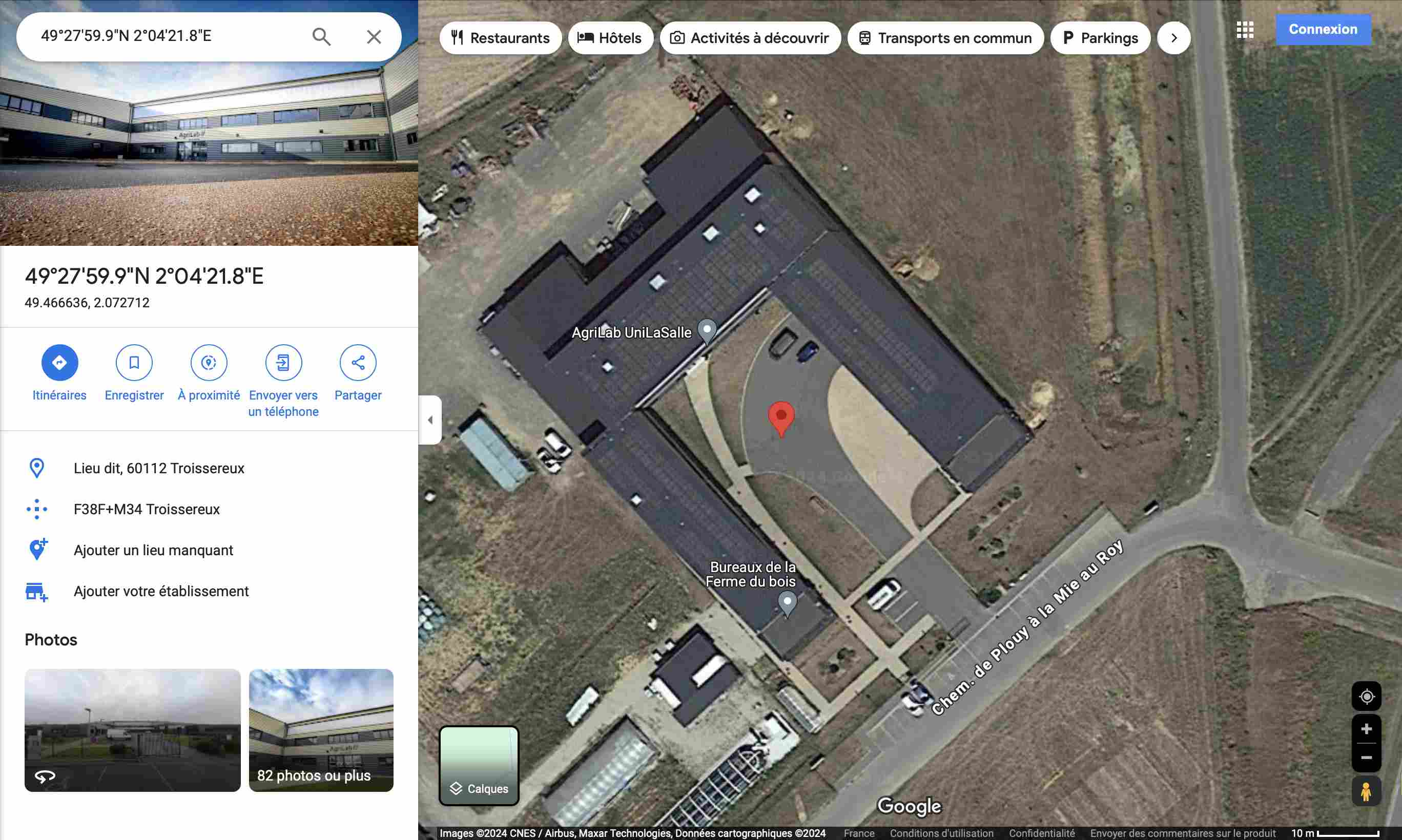
In order to check the consistency of the data received I went to check it on google maps by entering them in the search bar as follows Lattitude , Longitude so in my case 49.466636 , 2.072712.When I launch the search, the GPS positions me well in front of Agrilab, where I carried out my tests.
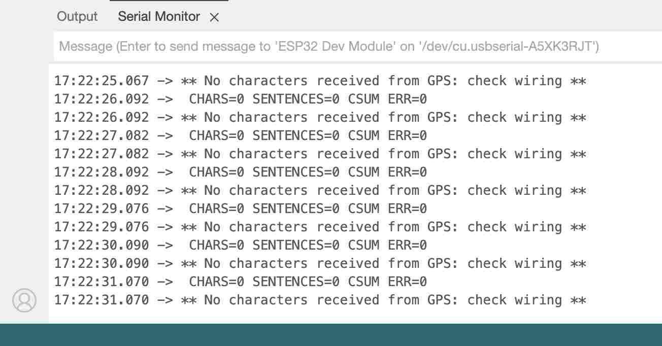
Following this success I then wanted to try to read the data with the first module I used and I still did not succeed using the same code. All I got were the following messages:
Networking and communication
During the networking and communication week, I was interested in remote control of my robot, notably using a remote control based on another ESP32 using the ESP NOW communication protocol.
In order to use wireless communication, I had a number of options open to me, including radio frequency, Bluetooth and WiFi. As I've already started using ESP32 for my final project, I chose to use the protocol ESP-NOW developed by Espressif. You can also find out more about how this bookstore works at documentation by Espressif and on the Github repository of the library. This protocol is based on the wifi network, but does not obey the wifi protocol but its own protocol. This technology makes it possible to exploit wifi properties up to a range of 200m between two esp32s. However, this protocol is only applicable between esp32 devices, so it is already present in the ESP32 library examples. This communication mode can be used in both directions or only in one direction. In my case, it only works in one direction. I ask my esp32 master, which will be the remote control, to send data to my esp32 slave, which is the circuit I've created to control my robot. To access the examples proposed by espressif, simply follow the path File > Exemples > ESP32 > ESPNow > ESPNow_Basic_Master/Slave.

To make the codes work, you'll first need to upload the code to the slave esp32, and when the code starts, you'll need to reserve the mac address which will be displayed. Each microcontroller has its own mac address, which will enable the master to send data only to this esp32 and not to all the others.
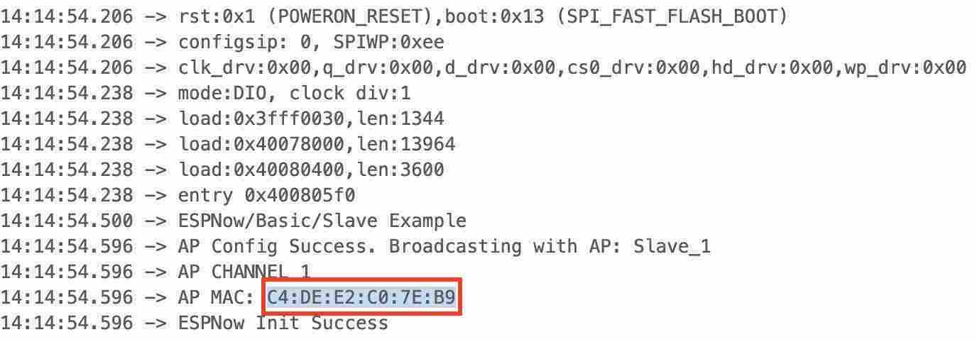
(In this example, it's the mac address of the master I used for the final code at the bottom of the page, not the slave.)
Once we have the MAC address of our slave, we can enter it in the master's code, with this line in my case:
uint8_t broadcastAddress[] = {0xC4, 0xDE, 0xE2, 0xC0, 0x7E, 0xB9};
Use the following codes for both slave and master to establish communication and send data. This code is based on the ESPNow example code proposed by Espressif, as well as another example from the site techtutorials. I also consulted the documentation on other websites, such as Raspberryme ou Random nerd tutorials. The esp32 I used are for the slave, the PCB I made during the electronic design week and as a master ESP32-DevKitC V4.
Below you will find the Master and Slav codes used.
Joystick and driver
Once I'd managed to send information without too much difficulty, I reworked the code so as to be able to send concrete data. In my case, I connected the master to a joystick so as to use it as a remote control. The aim is to be able to remotely control the robot in my final project, and also use the remote control to switch from automatic to manual mode. To do this, I connected my master to a joystick to control the robot, as follows:
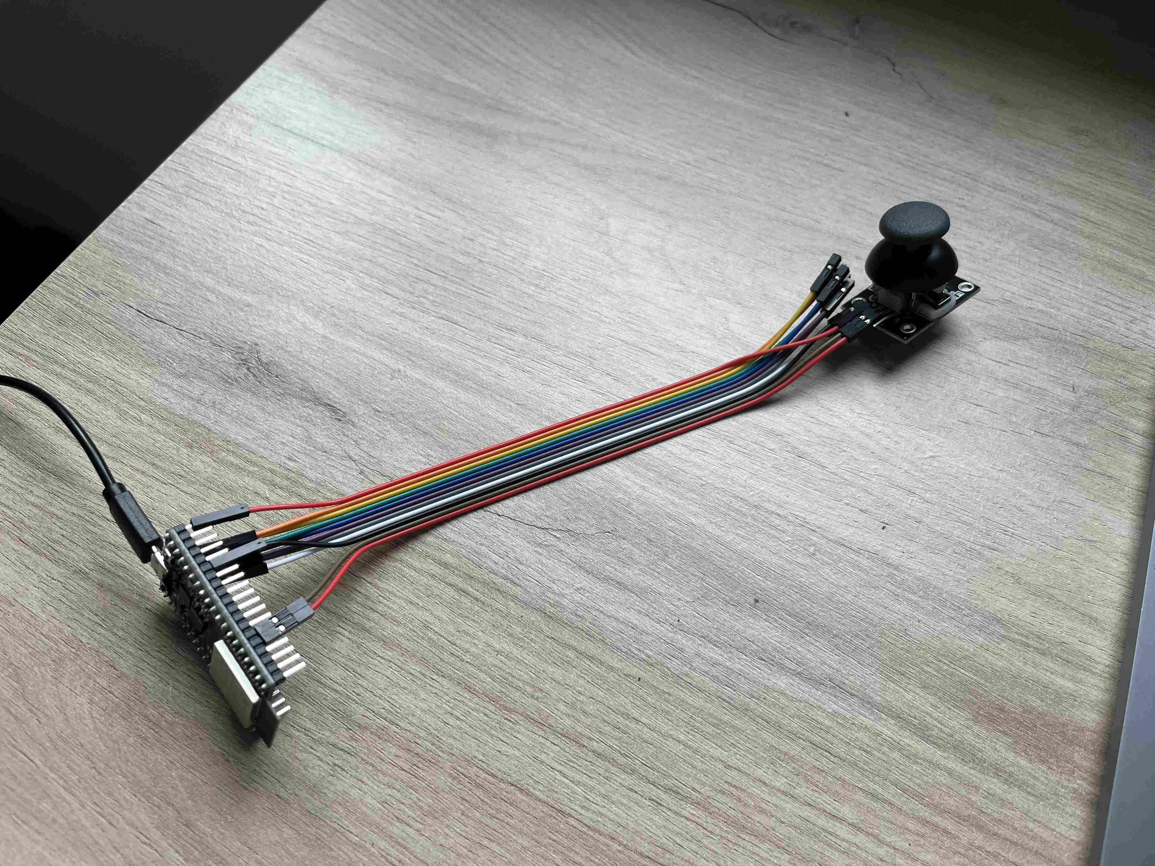
| Pin esp32 dev kit | Pin joystick |
|---|---|
| GND | GND |
| 5V | 5V |
| X axis | 35 |
| Y axis | 34 |
As for the Slave part, I connected my driver in the same way as I did during the week. Output devices.
As far as the code is concerned, for the moment I'm only interested in the forward motion, so when I push the joystick, the robot moves forward. I used the map() in order to correlate the values read on the joystick with the PWM of my motor. The codes used were the same as below:
Master
#include
#include
#include  // only for esp_wifi_set_channel()


// Global copy of slave
esp_now_peer_info_t slave;
#define CHANNEL 1
#define PRINTSCANRESULTS 0
#define DELETEBEFOREPAIR 0
//uint8_t broadcastAddress[] = {0xC4, 0xDE, 0xE2, 0xC0, 0x7E, 0xB9}
uint8_t broadcastAddress[] = {0xAC, 0x67, 0xB2, 0x75, 0x42, 0xE1};

//uint8_t data = 0; //valeur envoyee
//uint8_t data[3] = {0, 0, 0}; //valeur envoyee
const int buttonPin = 27;
const int axisY = 34;
const int axisX = 35;
int buttonState = 0;
int button;
int avance=0;
int direction=0;
int test=0;
typedef struct joystick_data {
  int button;
  int axisY;
  int axisX;
} joystick_data;


// Init ESP Now with fallback
void InitESPNow() {
  WiFi.disconnect();
  if (esp_now_init() == ESP_OK) {
    Serial.println("ESPNow Init Success");
  }
  else {
    Serial.println("ESPNow Init Failed");
    // Retry InitESPNow, add a counte and then restart?
    // InitESPNow();
    // or Simply Restart
    ESP.restart();
  }
}

// Scan for slaves in AP mode
void ScanForSlave() {
  int16_t scanResults = WiFi.scanNetworks(false, false, false, 300, CHANNEL); // Scan only on one channel
  // reset on each scan
  bool slaveFound = 0;
  memset(&slave, 0, sizeof(slave));

  Serial.println("");
  if (scanResults == 0) {
    Serial.println("No WiFi devices in AP Mode found");
  } else {
    Serial.print("Found "); Serial.print(scanResults); Serial.println(" devices ");
    for (int i = 0; i < scanResults; ++i) {
      // Print SSID and RSSI for each device found
      String SSID = WiFi.SSID(i);
      int32_t RSSI = WiFi.RSSI(i);
      String BSSIDstr = WiFi.BSSIDstr(i);

      if (PRINTSCANRESULTS) {
        Serial.print(i + 1);
        Serial.print(": ");
        Serial.print(SSID);
        Serial.print(" (");
        Serial.print(RSSI);
        Serial.print(")");
        Serial.println("");
      }
      delay(10);
      // Check if the current device starts with `Slave`
      if (SSID.indexOf("Slave") == 0) {
        // SSID of interest
        Serial.println("Found a Slave.");
        Serial.print(i + 1); Serial.print(": "); Serial.print(SSID); Serial.print(" ["); Serial.print(BSSIDstr); Serial.print("]"); Serial.print(" ("); Serial.print(RSSI); Serial.print(")"); Serial.println("");
        // Get BSSID => Mac Address of the Slave
        int mac[6];
        if ( 6 == sscanf(BSSIDstr.c_str(), "%x:%x:%x:%x:%x:%x",  &mac[0], &mac[1], &mac[2], &mac[3], &mac[4], &mac[5] ) ) {
          for (int ii = 0; ii < 6; ++ii ) {
            slave.peer_addr[ii] = (uint8_t) mac[ii];
          }
        }

        slave.channel = CHANNEL; // pick a channel
        slave.encrypt = 0; // no encryption

        slaveFound = 1;
        // we are planning to have only one slave in this example;
        // Hence, break after we find one, to be a bit efficient
        break;
      }
    }
  }

  if (slaveFound) {
    Serial.println("Slave Found, processing..");
  } else {
    Serial.println("Slave Not Found, trying again.");
  }

  // clean up ram
  WiFi.scanDelete();
}

// Check if the slave is already paired with the master.
// If not, pair the slave with master
bool manageSlave() {
  if (slave.channel == CHANNEL) {
    if (DELETEBEFOREPAIR) {
      deletePeer();
    }

    Serial.print("Slave Status: ");
    // check if the peer exists
    bool exists = esp_now_is_peer_exist(slave.peer_addr);
    if ( exists) {
      // Slave already paired.
      Serial.println("Already Paired");
      return true;
    } else {
      // Slave not paired, attempt pair
      esp_err_t addStatus = esp_now_add_peer(&slave);
      if (addStatus == ESP_OK) {
        // Pair success
        Serial.println("Pair success");
        return true;
      } else if (addStatus == ESP_ERR_ESPNOW_NOT_INIT) {
        // How did we get so far!!
        Serial.println("ESPNOW Not Init");
        return false;
      } else if (addStatus == ESP_ERR_ESPNOW_ARG) {
        Serial.println("Invalid Argument");
        return false;
      } else if (addStatus == ESP_ERR_ESPNOW_FULL) {
        Serial.println("Peer list full");
        return false;
      } else if (addStatus == ESP_ERR_ESPNOW_NO_MEM) {
        Serial.println("Out of memory");
        return false;
      } else if (addStatus == ESP_ERR_ESPNOW_EXIST) {
        Serial.println("Peer Exists");
        return true;
      } else {
        Serial.println("Not sure what happened");
        return false;
      }
    }
  } else {
    // No slave found to process
    Serial.println("No Slave found to process");
    return false;
  }
}

void deletePeer() {
  esp_err_t delStatus = esp_now_del_peer(slave.peer_addr);
  Serial.print("Slave Delete Status: ");
  if (delStatus == ESP_OK) {
    // Delete success
    Serial.println("Success");
  } else if (delStatus == ESP_ERR_ESPNOW_NOT_INIT) {
    // How did we get so far!!
    Serial.println("ESPNOW Not Init");
  } else if (delStatus == ESP_ERR_ESPNOW_ARG) {
    Serial.println("Invalid Argument");
  } else if (delStatus == ESP_ERR_ESPNOW_NOT_FOUND) {
    Serial.println("Peer not found.");
  } else {
    Serial.println("Not sure what happened");
  }
}

void setup() {
  Serial.begin(115200);
  //Set device in STA mode to begin with
  WiFi.mode(WIFI_STA);
  esp_wifi_set_channel(CHANNEL, WIFI_SECOND_CHAN_NONE);
  Serial.println("ESPNow/Basic/Master Example");
  // This is the mac address of the Master in Station Mode
  Serial.print("STA MAC: "); Serial.println(WiFi.macAddress());
  Serial.print("STA CHANNEL "); Serial.println(WiFi.channel());
  // Init ESPNow with a fallback logic
  InitESPNow();
  // Once ESPNow is successfully Init, we will register for Send CB to
  // get the status of Trasnmitted packet
 //esp_now_register_send_cb(OnDataSent);
}

void loop() {
  // In the loop we scan for slave
  ScanForSlave();
  // If Slave is found, it would be populate in `slave` variable
  // We will check if `slave` is defined and then we proceed further
  if (slave.channel == CHANNEL) { // check if slave channel is defined
    // `slave` is defined
    // Add slave as peer if it has not been added already
    bool isPaired = manageSlave();
    if (isPaired) {
      // pair success or already paired
      // Send data to device
      sendData();
    } else {
      // slave pair failed
      Serial.println("Slave pair failed!");
    }
  }
  //else {
    // No slave found to process
  //}
joystick_data test;
    button=buttonPin;
    avance=analogRead(axisX);
    direction=analogRead(axisY);


  //// wait for 3seconds to run the logic again
  delay(100);

//  buttonState = digitalRead(buttonPin);
//  if (buttonState == HIGH) {
//    data[0] = 1;
//  }


}

// send data
void sendData() {
  const uint8_t *peer_addr = slave.peer_addr;
//  joystick_data test;
//  avance=analogRead(axisX);
//  direction=analogRead(axisY);
  Serial.print("Sending: "); Serial.println(test);
  //esp_err_t result = esp_now_send(peer_addr, (uint8_t *) &test.x, sizeof(test.x));//&data, sizeof(data));
  esp_err_t result = esp_now_send(
    broadcastAddress,
    (uint8_t *) &test,
    sizeof(joystick_data));

  Serial.print("Send Status: ");
  if (result == ESP_OK) {
    Serial.println("Success");
  //  test_struct = 0;
  } else if (result == ESP_ERR_ESPNOW_NOT_INIT) {
    // How did we get so far!!
    Serial.println("ESPNOW not Init.");
  } else if (result == ESP_ERR_ESPNOW_ARG) {
    Serial.println("Invalid Argument");
  } else if (result == ESP_ERR_ESPNOW_INTERNAL) {
    Serial.println("Internal Error");
  } else if (result == ESP_ERR_ESPNOW_NO_MEM) {
    Serial.println("ESP_ERR_ESPNOW_NO_MEM");
  } else if (result == ESP_ERR_ESPNOW_NOT_FOUND) {
    Serial.println("Peer not found.");
  } else {
    Serial.println("Not sure what happened");
  }
  delay(100);
}
Slave
#include
#include
// Define pins for steering control
const int DIR = 33;
//  PWM spindle for speed control
const int PWM_PIN = 32;
int button;
int avance_value = 0;
int direction_value = 0;

int test=0;
typedef struct joystick_data {
  int button;//première ligne du struct n'est pas lu est attribue directement la valeur 0
  int avance;
  int direction;
} joystick_data;

#define CHANNEL 1

// Init ESP Now with fallback
void InitESPNow() {
  WiFi.disconnect();
  if (esp_now_init() == ESP_OK) {
    Serial.println("ESPNow Init Success");
  }
  else {
    Serial.println("ESPNow Init Failed");
    // Retry InitESPNow, add a counte and then restart?
    // InitESPNow();
    // or Simply Restart
    ESP.restart();
  }
}

// config AP SSID
void configDeviceAP() {
  const char *SSID = "Slave_1";
  bool result = WiFi.softAP(SSID, "Slave_1_Password", CHANNEL, 0);
  if (!result) {
    Serial.println("AP Config failed.");
  } else {
    Serial.println("AP Config Success. Broadcasting with AP: " + String(SSID));
    Serial.print("AP CHANNEL "); Serial.println(WiFi.channel());
  }
}

void setup() {
  Serial.begin(115200);
  Serial.println("ESPNow/Basic/Slave Example");
  //Set device in AP mode to begin with
  WiFi.mode(WIFI_AP);
  // configure device AP mode
  configDeviceAP();
  // This is the mac address of the Slave in AP Mode
  Serial.print("AP MAC: "); Serial.println(WiFi.softAPmacAddress());
  // Init ESPNow with a fallback logic
  InitESPNow();
  // Once ESPNow is successfully Init, we will register for recv CB to
  // get recv packer info.
  esp_now_register_recv_cb(OnDataRecv);

  //Driver
  pinMode(DIR, OUTPUT);//direction
  pinMode(PWM_PIN, OUTPUT);//speed

}

// callback when data is recv from Master
void OnDataRecv(const uint8_t *mac_addr, const uint8_t *data, int data_len) {
  char macStr[18];
  snprintf(macStr, sizeof(macStr), "%02x:%02x:%02x:%02x:%02x:%02x",
           mac_addr[0], mac_addr[1], mac_addr[2], mac_addr[3], mac_addr[4], mac_addr[5]);
  Serial.print("Last Packet Recv from: "); Serial.println(macStr);
  joystick_data* test =(joystick_data*) data;
  Serial.print("Last Packet Recv Data: Avancement= "); Serial.print(test->avance);
  Serial.print(", Direction=");Serial.println(test->direction);
  //Serial.print(", ");Serial.println(test->button);

  avance_value = test->avance;
  direction_value = test->direction;
}

void loop() {
int value_pwm = map(avance_value, 0, 4095, 0, 250);
  analogWrite(PWM_PIN, value_pwm);
  digitalWrite(DIR, HIGH);
  /*int value_pwm = map(dir, 0, 4095, O, 250);
  analogWrite(PWM_PIN, value_pwm);*/
  delay(100);
}
The result was as follows:
I then wanted to test it remotely, so I used an extension cord to power my master, and even at a distance of a dozen meters in Agrilab, even though you can't really see it on the video, it received the signal very well.
Following this test I slightly modified the code again, so you'll find the final code above, but it's not exactly the same as in the video test. In the master code, I've removed the function.
void OnDataSent()
This function let the master know whether the slave had received the data. The latter considerably increased the exchange time between the two, and I managed to drastically reduce the frequency of data transmission by removing it.
During this week, I had a lot of difficulty modifying my program to my liking, I don't have a very good level in programming and I spent a lot of time understanding and modifying the program to make it execute the actions I wanted.
Electronic design
Once my code was working well, I started designing a circuit on Kicad in order to integrate a remote control with all the components I would need. It has a microcontroller Xiao esp32C3. In addition to the microcontroller, I've added:
-Two switch slide buttons
-One Conn pinheader femaleX5
Two resistors 10kOhm
The aim is to use one of the buttons to tell me whether the robot should be running or switched off, while the second is designed to indicate whether the robot is running using the remote control or whether it should go into automatic mode. You can find the kicad design file here here.
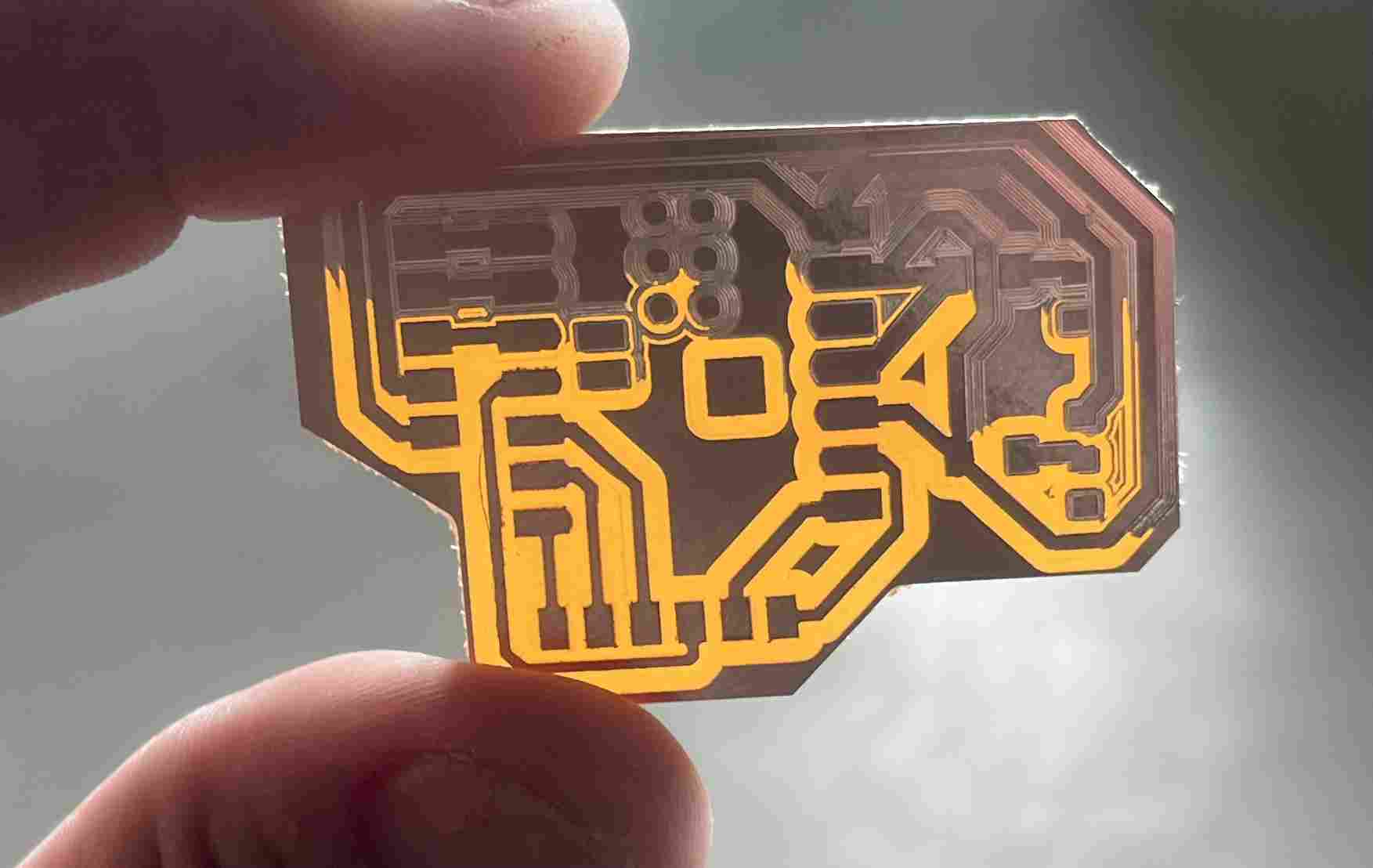
The result wasn't very satisfactory, the milling wasn't done properly on the top of the PCB and so I cut the tracks with the ultrasonic blade, which took a lot of time. The final result after soldering was as follows:
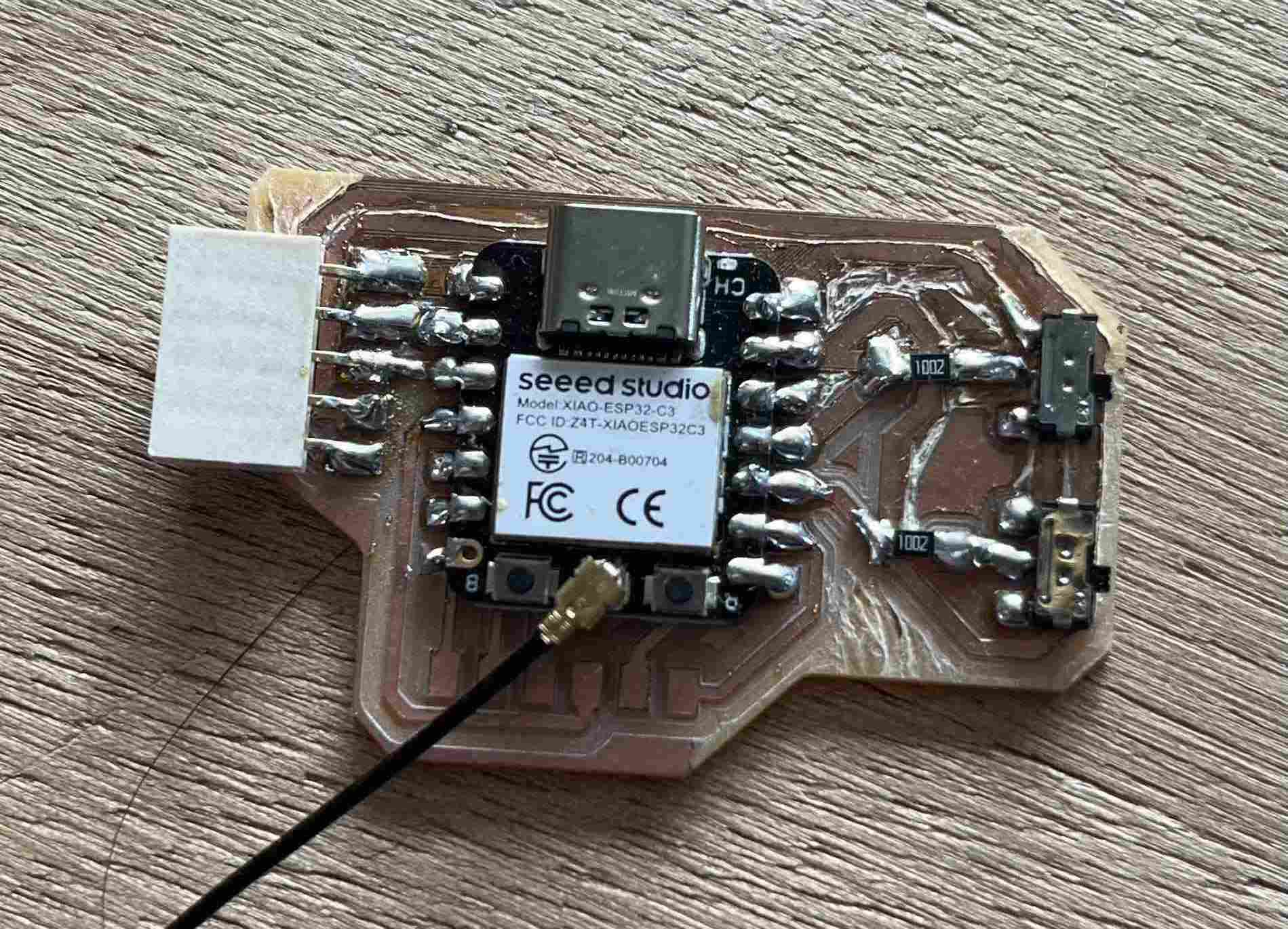
I'm not really satisfied with the result, the ESP32 doesn't really work satisfactorily, once the code has been uploaded, nothing is displayed in the serial monitor, I can't send any communication.
Image recognition
During week 15, we could choose to work on an area that we didn't cover during the fabacademy, so in order to make progress on my robot project, I decided to look at camera recognition via openCV and other technologies.
Material
To start the week Luc, our instructor, gave me everything I needed to get started. To wit:
-A raspberry pi 5
-A raspberry module 3 camera
-A 27watt power supply
-A keyboard
-A mouse
-HDMI to micro-HDMI cable
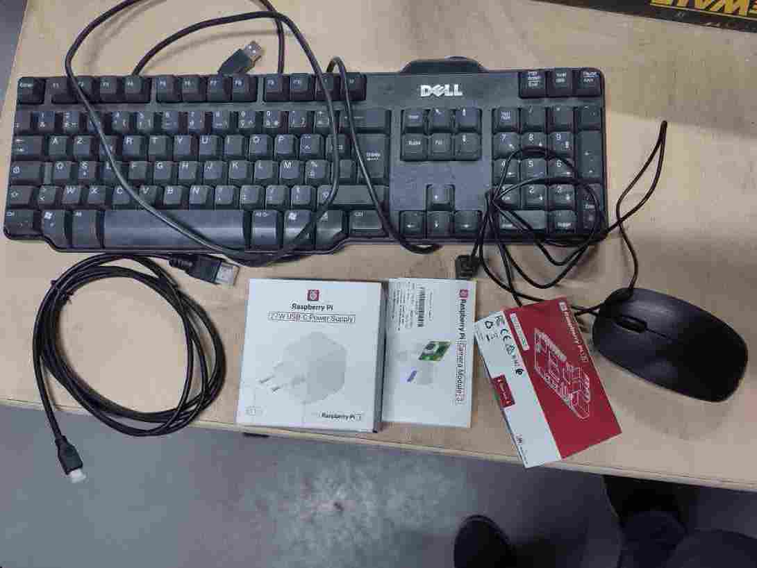
To manage the screen display, I used video projectors, as the display did not display well on the 4K TV screens we have at agrilab and we didn't have an HDMI computer screen. It's possible to configure the Raspberry from another computer, but that's more complex and I'd never used one before, so it was simpler to use it like a conventional computer to start with.
Raspberry pi
The Raspberry Pi is a small, inexpensive and versatile single-board computer based on the Linux OS, designed to encourage learning to program and experiment with computing. It is equipped with an ARM processor, USB, HDMI and Ethernet ports, as well as GPIO pins for connecting to electronic components. The Raspberry Pi runs various operating systems, mainly Linux distributions such as Raspbian. It is widely used for DIY projects, home automation, teaching computer science and developing prototypes.(Description from ChatGPT)
Installation of the operating system
In order to use the raspberry, we first need to download an operating system. To do this, I used this tutorial very simple to follow proposed by raspberry. First of all we need to download theraspberry pi imager.
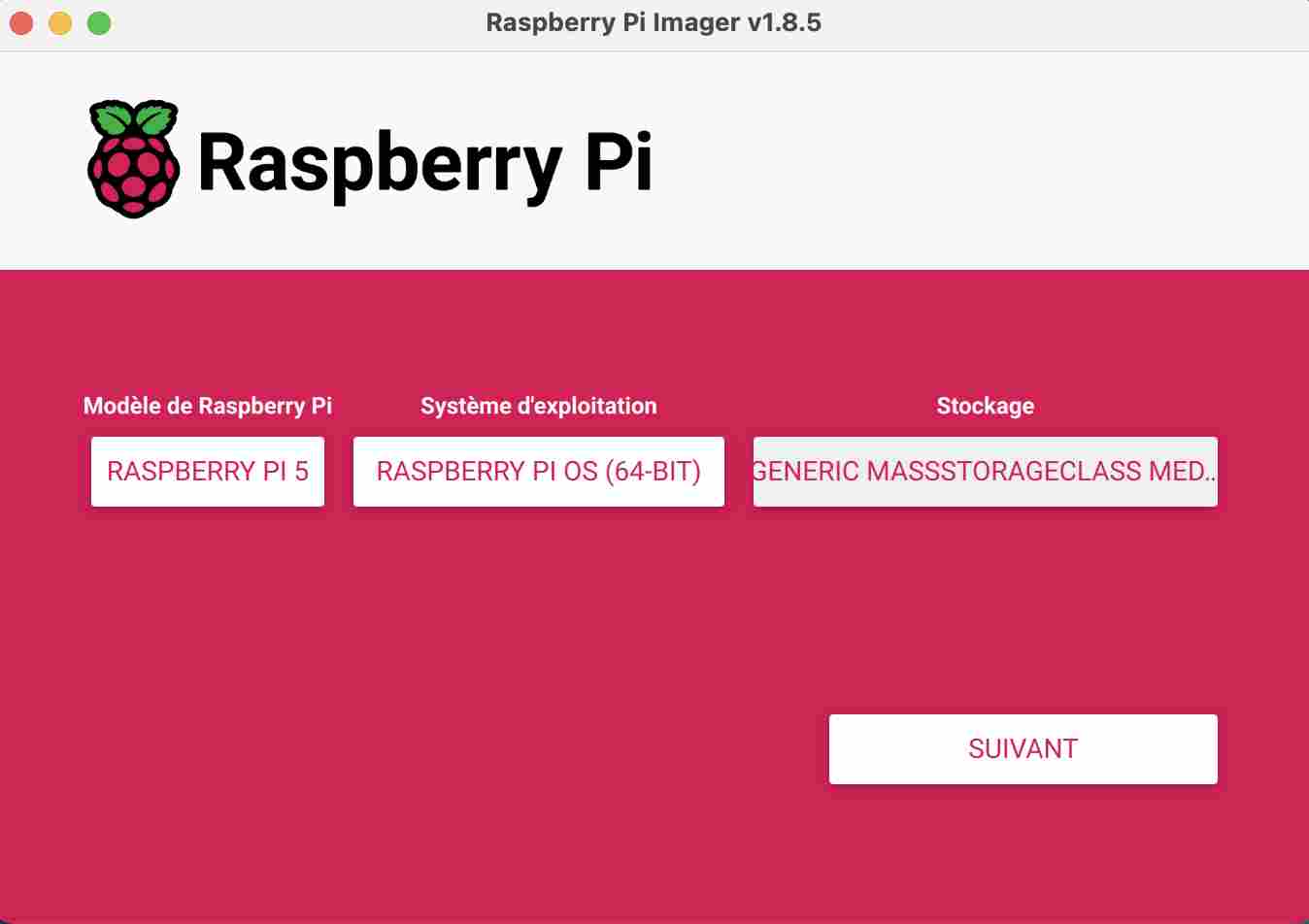
It's fairly simple to use, you just need to connect the raspberry sd card to your computer and go through the steps one by one. First, we select the model of raspberry we're using, in my case the Raspberry pi 5.
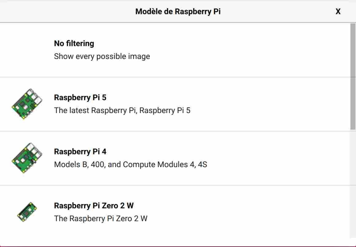
We then select the operating system we are going to use, in my case I used the one that was recommended which is the Pi OS 64bits.
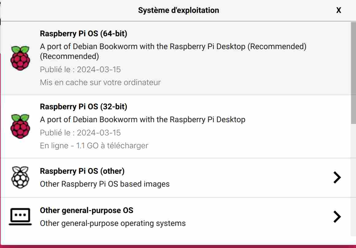
All that remains is to select our storage device and then we can proceed with customisation.
First, we'll choose the host name and user, and configure the wifi and local settings.
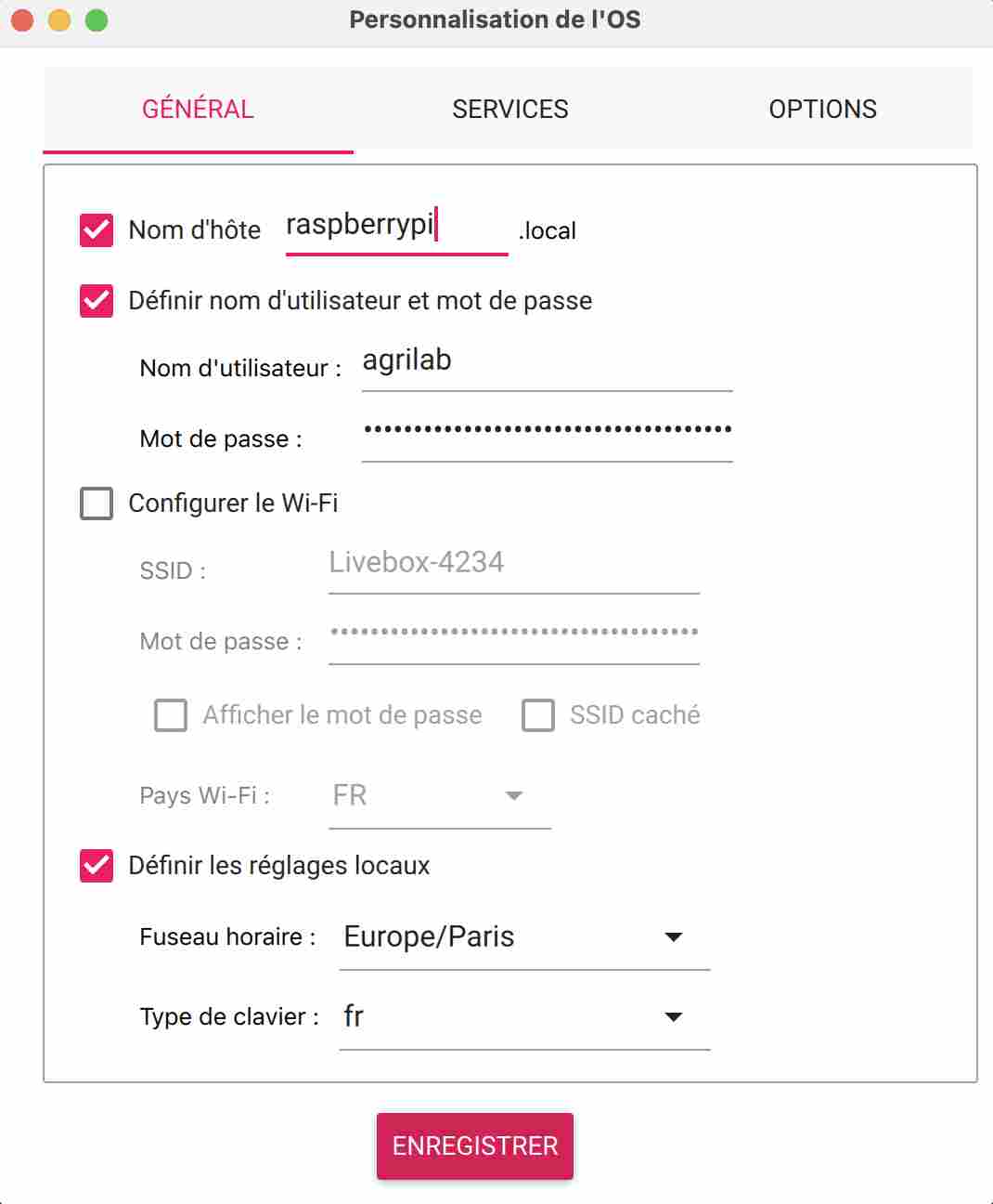
You can then choose to activate an ssh key and select certain options. We can then exit and choose to install the custom settings. Installing the OS doesn't take very long, and once it's finished you can put the micro SD card back in your Raspberry.
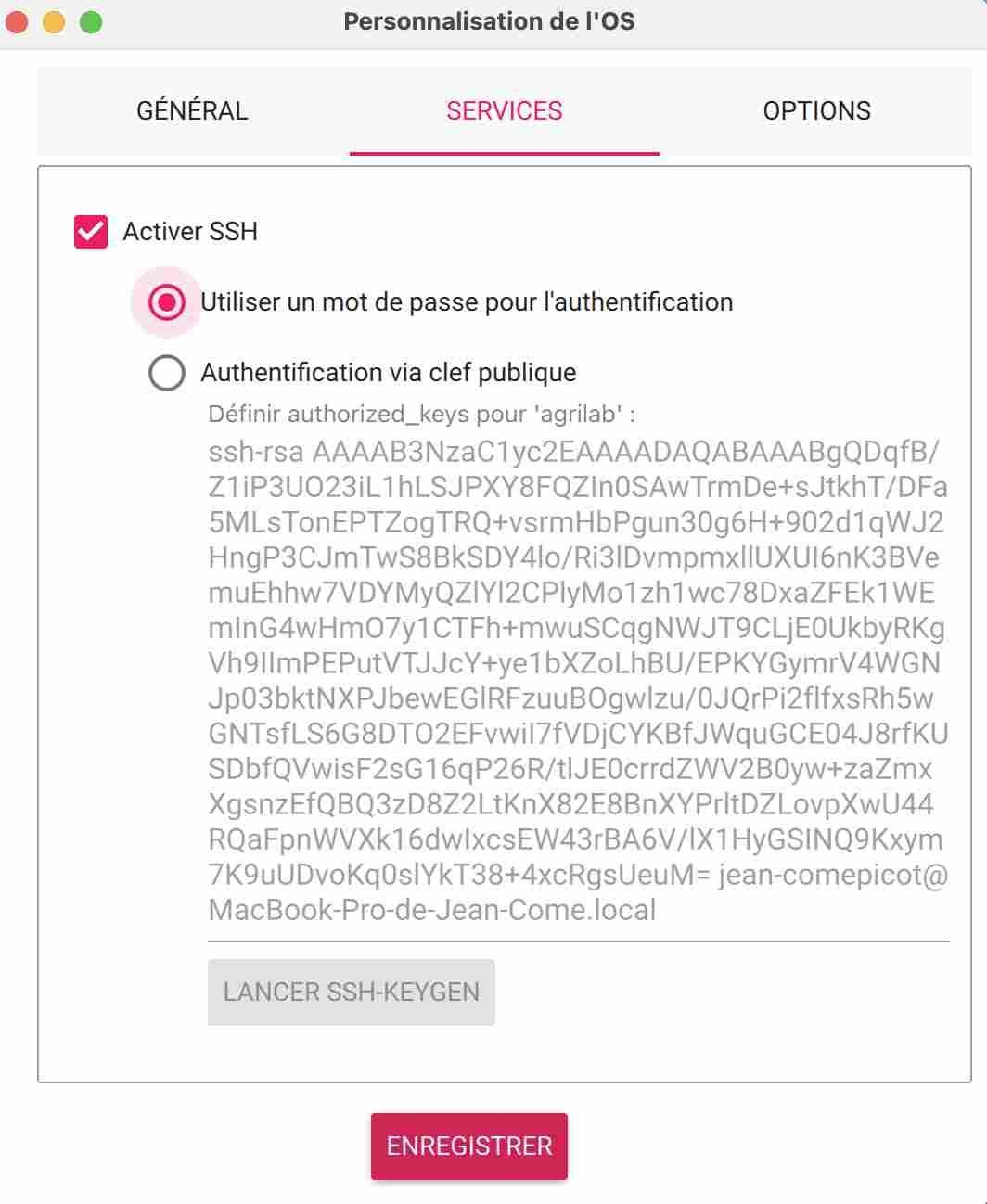
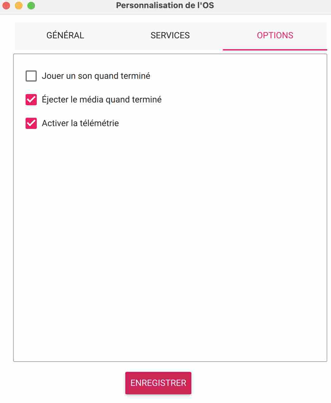
OpenCV
OpenCV (Open Source Computer Vision Library) is an open-source library specialising in image processing and computer vision. It offers a wide range of functions for capturing, processing, analysing and manipulating images and videos in real time. OpenCV is written in C++ and provides interfaces for the most common programming languages such as Python, Java and MATLAB. It is widely used in a variety of fields, including facial recognition, object detection, machine vision, augmented reality and robotics. Thanks to its open-source nature and active community, OpenCV is constantly being enhanced with new features and improvements.(Description from ChatGPT)
OpenCV installation
Installing the library wasn't easy, I had problems with the different methods being so diverse and varied that I found myself lost in all the online documentation. It was a discovery for me, both in terms of Linux and how to use it, and in terms of the raspberry pi. Initially, I used this tutorial from Qengineering. It's quite long and very well informed, but I got lost as I went along, no doubt entering the wrong commands. The tutorial explained how to download in python as well as in C++. Being fairly familiar with the C++ language, I initially wanted to choose this method. But then I realised that there was much more extensive documentation in Python, so I opted for that language again. So I gave up and reformatted my SD card so as not to create conflicts between the different versions of openCV that I had installed.
On my second attempt, I usedthis tutorial from RaspberryTips. It was much simpler to download openCV and all you had to do was enter the following command line in the terminal:
sudo apt install python3-opencv
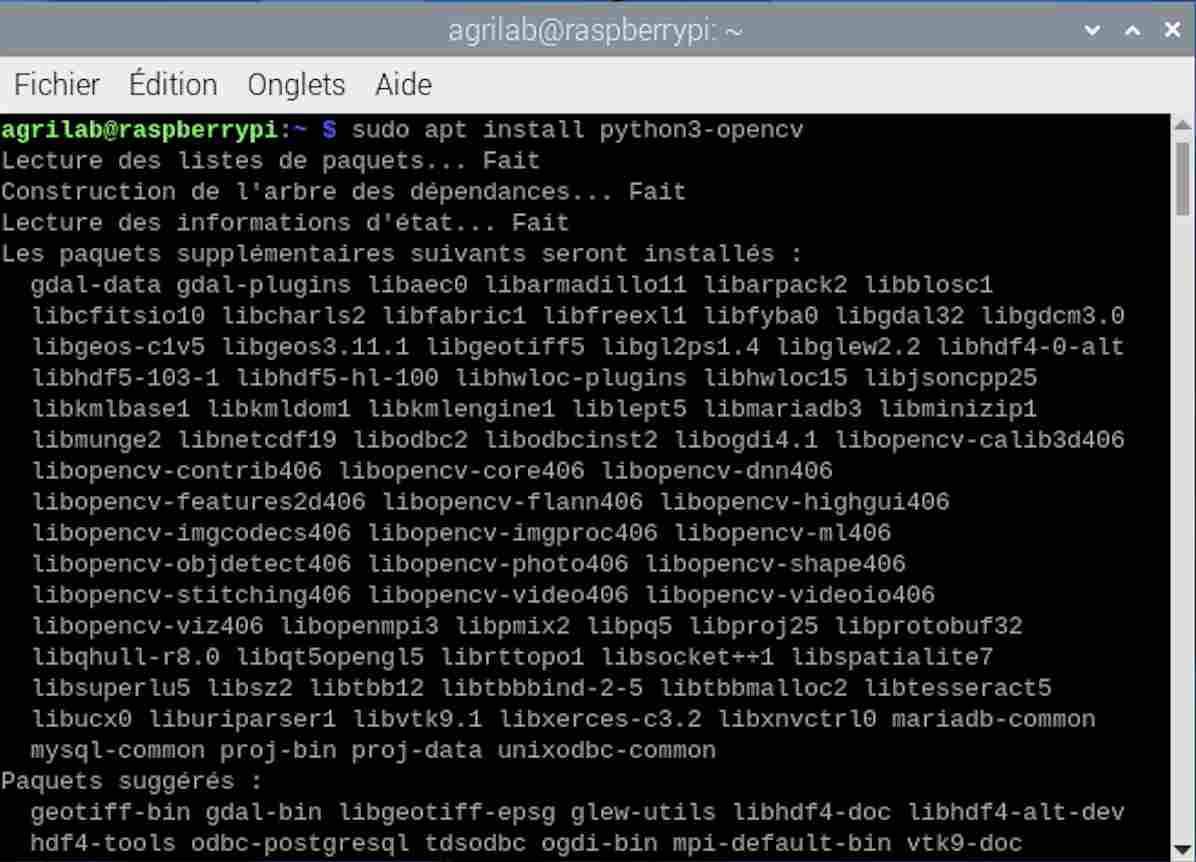
I then continued to follow the tutorial to test whether the installation had been successful by entering the following command lines.
										import cv2
										cv2.__version__
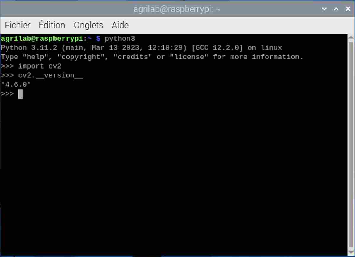
You can see that the installation was successful and that in my case I have the version 4.6.0 of OpenCV. You can enter these command lines directly in the terminal, as I did by calling python first, or by entering them in Thonny, which is installed by default in the OS.
Vision with Raspberry Cam
For try the vision with Raspberry camera, I tried to follow this tutorial from Framboise 314(french). I didn't get very far in pursuing it because it was the first time we'd used a Raspberry PI 5 with the camera at Agrilab and we didn't manage to connect it because the ribbon that connects the camera to the Raspberry isn't the same as on older generations, so I wasn't able to try using the Raspberry with the camera and had to resort to using photos from the web in the meantime. I may also try other tutorials such as this one.
Roboflow trial
I then tried to test an already pre-trained model on the roboflow site using this model which is trained on 271 images of crows. However, to install it I had to create a virtual environment to avoid any problems between different versions of the software.
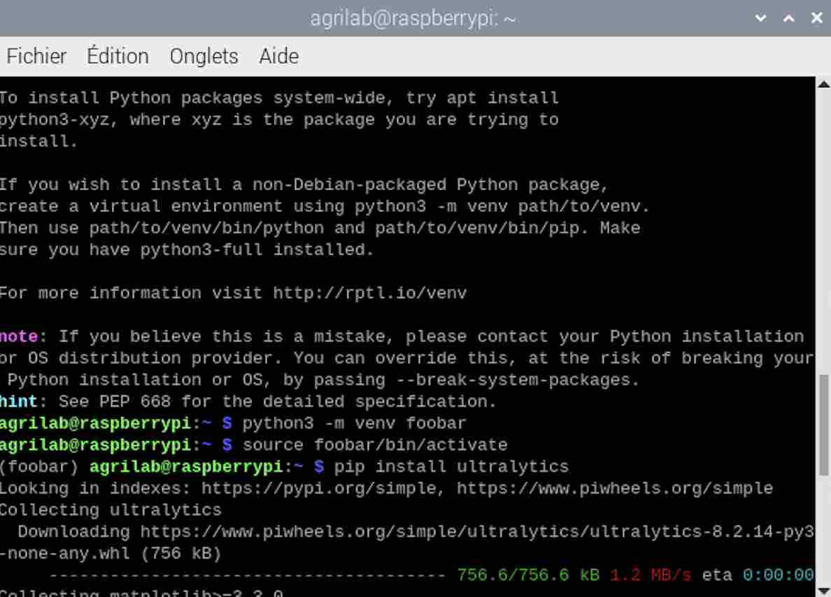
Once I had my virtual environment here called foobar I first entered this command in my monitor:
pip install inference-sdk
I then tried this code in thonny and an image downloaded from the Internet.
from inference_sdk import InferenceHTTPClient

CLIENT = InferenceHTTPClient(
    api_url="https://detect.roboflow.com",
    api_key="API_KEY"
)

result = CLIENT.infer(your_image.jpg, model_id="cigritous/1")
The result was a failure and it didn't work. I think the fact that the tool was downloaded in a virtual environment makes it more complex to use. I saw in this tutorial that it is possible to disable the security that forces the creation of a virtual environment by entering this command line in the terminal:
sudo mv /usr/lib/python3.11/EXTERNALLY-MANAGED /usr/lib/python3.11/EXTERNALLY-MANAGED.old
Spaces of colors
I then looked to see if there were other systems using OpenCV to determine whether they were crows or not and I came across this scientific article which tests two methods by comparing Tensorflow and OpenCV. I tried to follow it, but I tried different codes because I was having trouble downloading new libraries and using them in my virtual environment. So I used this tutorial to analyse the different colour spaces in a photo of a raven. To do this I started by trying to determine the HSV (Hue, Saturation, Value) space of my image. To do this I used the following code:
import cv2
img = cv2.imread("/home/agrilab/Desktop/original.jpg", cv2.IMREAD_UNCHANGED)
hsv = cv2.cvtColor(img, cv2.COLOR_BGR2HSV)
cv2.namedWindow('hsv', cv2.WINDOW_NORMAL)
cv2.imshow('hsv', hsv)
cv2.waitKey(0)
cv2.destroyAllWindows()
The result was quite satisfactory and was as follows:
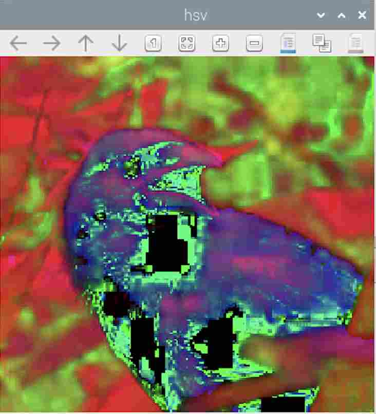
I then tried transforming the image into greyscale, using the following code
import cv2
img = cv2.imread("/home/agrilab/Desktop/original.jpg", cv2.IMREAD_UNCHANGED)
gray = cv2.cvtColor(img, cv2.COLOR_BGR2GRAY)
cv2.namedWindow('gray', cv2.WINDOW_NORMAL)
cv2.imshow('gray', gray)
cv2.waitKey(0)
cv2.destroyAllWindows()
I obtained the following result:
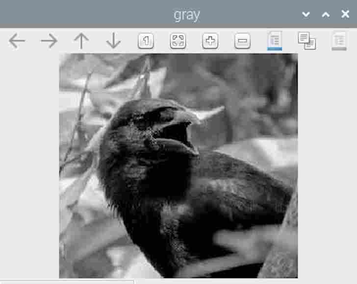
I then tried a code that separates the objects in an image, the code was as follows:
import cv2
import numpy as np
img=cv2.imread ("/home/agrilab/Desktop/original.jpg");
hsv = cv2.cvtColor(img, cv2.COLOR_BGR2HSV)
h,s,v= cv2.split(hsv)
ret_h, th_h = cv2.threshold(h,0,255,cv2.THRESH_BINARY+cv2.THRESH_OTSU)
ret_s, th_s = cv2.threshold(s,0,255,cv2.THRESH_BINARY+cv2.THRESH_OTSU)
#Fusion th_h et th_s
th=cv2.bitwise_or(th_h,th_s)
#Ajouts de bord à l'image
bordersize=10
th=cv2.copyMakeBorder(th, top=bordersize, bottom=bordersize, left=bordersize, right=bordersize, borderType= cv2.BORDER_CONSTANT, value=[0,0,0] )
#Remplissage des contours
im_floodfill = th.copy()
h, w = th.shape[:2]
mask = np.zeros((h+2, w+2), np.uint8)
cv2.floodFill(im_floodfill, mask, (0,0), 255)
im_floodfill_inv = cv2.bitwise_not(im_floodfill)
th = th | im_floodfill_inv
#Enlèvement des bord de l'image
th=th[bordersize: len(th)-bordersize,bordersize: len(th[0])-bordersize]
resultat=cv2.bitwise_and(img,img,mask=th)
cv2.imwrite("im_floodfill.jpg",im_floodfill)
cv2.imwrite("th.jpg",th)
cv2.imwrite("resultat.jpg",resultat)
contours, hierarchy = cv2.findContours(th,cv2.RETR_TREE,cv2.CHAIN_APPROX_SIMPLE)
for i in range (0, len(contours)) :
    mask_BB_i = np.zeros((len(th),len(th[0])), np.uint8)
    x,y,w,h = cv2.boundingRect(contours[i])
    cv2.drawContours(mask_BB_i, contours, i, (255,255,255), -1)
    BB_i=cv2.bitwise_and(img,img,mask=mask_BB_i)
    if h >15 and w>15 :
        BB_i=BB_i[y:y+h,x:x+w]
        cv2.imwrite("BB_"+str(i)+".jpg",BB_i)
The result wasn't very satisfactory, as I got a lot of images that didn't necessarily display what I was looking for, such as the following:

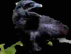


As I couldn't copy the principle of using the page any further, I finally decided not to go any further in this tutorial.
Open CV bird détectection algorythm
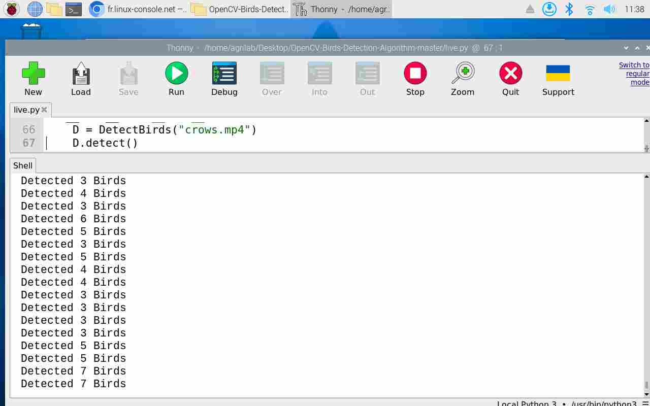
I then found this Github deposit which allows you to do bird recognition with openCV. So I cloned the github repository and tried it out on my raspberry. To do this, I went to the folder and opened the file in python then ran it, the result on the demonstration video was not very satisfactory, it took birds into account during flight but no longer detected them once they had landed, as can be seen below. It also counted the number of birds with completely inaccurate values.
So I tried testing it with other videos by adding them to the folder and replacing a line in the code with the name of the example video. I used this recording from a youtube vidéo to see how the algorithm behaved when faced with a crow, then I tried, with Luc's advice, to take a video that had nothing to do with birds and even less with animals. So I also tried a test video of the week5 or I pour water into a glass to see if the algorithm is reliable enough.
As you can see from the videos, the result is not really satisfactory. In the video of the crows, we can see that the algorithm does detect the presence of animals, but it's very random and not very effective. In the case of the second video we can see that the algorithm really doesn't work, we don't see any moving objects or animals and we see squares being displayed when there's no reason for them to be, so this test wasn't a very good lead. As for the test with the video of the crows, you can also see that the number of crows counted in the serial monitor has nothing to do with the real number of birds. I don't know why, but the video was inverted when it was processed by the algorithm.
Sources codes
-Test HSV
-Test grey
-Object cutting test
System integration
During my system integration week, I wanted to work on and highlight the various points on which I had worked and on which I still had progress to make. I particularly worked on the sizing of my motors, and you can find the different stages below.
Motor Sizing
We are quickly approaching the submission of our final project, and it is time to make some very important choices. This week, I decided on the motors I would use to operate my robot. The calculations I performed were quite random since each value is estimated and not an exact value. To proceed with calculating the different parameters of my motors, I used a tutorial provided by the website DFRobot that I followed step by step.
First, I needed to calculate the system parameters. For this, I estimated my robot’s weight to be 20kg, although I am not sure of the final weight, and it will probably be higher rather than lower than these 20kg. Regarding friction, I need to be able to roll in very difficult conditions in the fields, so I found this website. To take maximum precautions, I used the most difficult conditions proposed, a friction factor of 0.7, which corresponds to clean sound rock. I also needed to determine the acceleration. In my case, I chose a value of 7km/h over a duration of 5 seconds, as in the tutorial, which is almost 2m/s.
| Factor | Value |
|---|---|
| Robot weight | 20kg |
| Friction factor | 0.7 |
| Acceleration | 2m/s in 5s |
I then performed the following calculations:
N = 20 kg X 9.8 N/kg = 196 N
Ffriction = 0.7 X 196 N = 137.2 N
I then calculated the acceleration using the formula Facceleration=m(mass) X a(acceleration) and obtained the following results
a = (2 m/s) / 5 s = 0.4 m/s²
Facceleration = 20 kg X 0.4 N/kg = 8 N
F = Ffriction + Facceleration = 137.2 N + 8 N = 145.2 N
We therefore obtain a total force of our robot of 145.2N. I then needed to determine the diameter of the wheels I would use. In my case and in the context of my robot concept, I chose to have very large diameter wheels, which implies a very high force requirement. To ensure the bottom of my robot does not damage the crops, I chose a radius of 55cm. With these values, I was able to determine the torque(τ) and the number of wheel rotations per minute(rpm).
τ = (142 N X 0.55 m) / 2 = 39.93 Nm
n = (2 m/s X 60 s) / (2π X 0.55 m) ≈ 34.68 rpm
To ensure safety, the tutorial recommends oversizing with a factor of 1.5 to 2. In my case, already having a very high torque, I chose to oversize with only a factor of 1.5, which gives me the following result:
τ final = 39.93 Nm X 1.5 = 59.895 Nm
Therefore, I would need motors with a torque of 60Nm each, which is quite significant and implies using large motors or using a gear motor. Once these values were determined, we can look at the consumption of our motors. For this, I first considered 24V motors, then switched to 12V motors. The calculations were as follows:
ω = (34.68 rpm * 2π) / 60 ≈ 3.6 rad/s
P = 59.895 Nm * 3.6 rad/s ≈ 215.6 W
I = 215.6 W/12V = 17.96 A
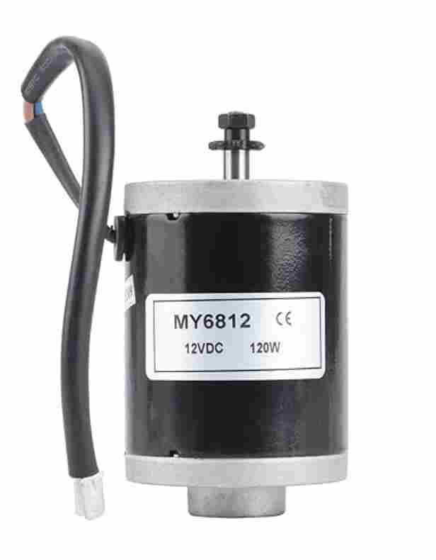
The values we can find as a result are very high and correspond to fairly expensive motors. We checked the calculations with Luc, and the results seem consistent, so we decided to opt for another type of motor with properties not exactly matching those calculated. For the sake of delivery speed and cost, we opted for MY6812 type electric motors, which are widely used for electric bikes and scooters. These still have good power, are highly developed, so they are inexpensive and can be delivered quickly. Using these motors with a very fast RPM (3500rpm) will, however, require a device to multiply the force exerted by my motor to have enough torque.
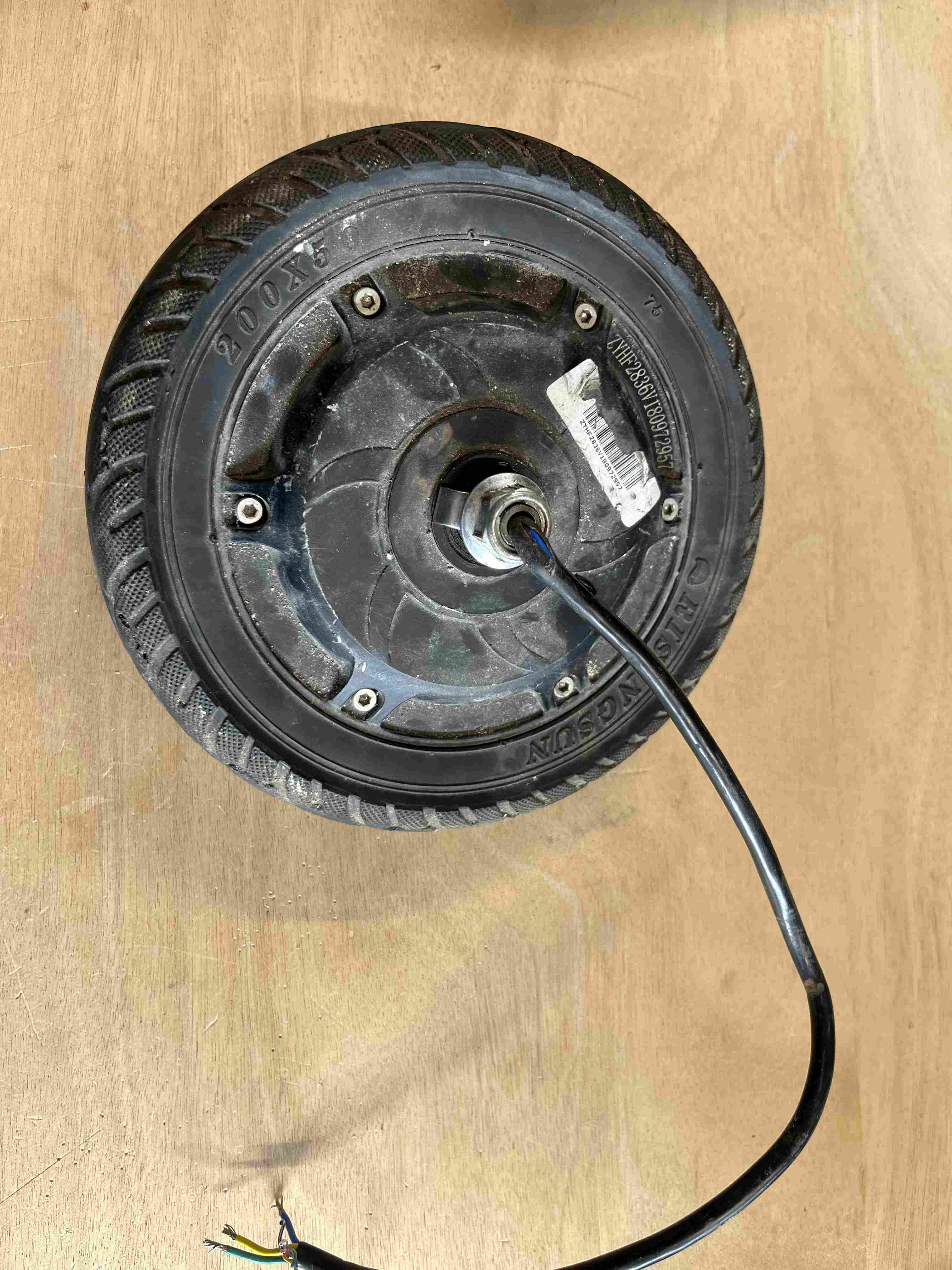
During my motor research, I also tried to test a brushless electric motor from a damaged electric scooter that was at agrilab. I tried to get the brushless motor to work but couldn't, and gave up when I realized that we only had one scooter after all, and that there was no need to waste any more time with this solution.
Battery
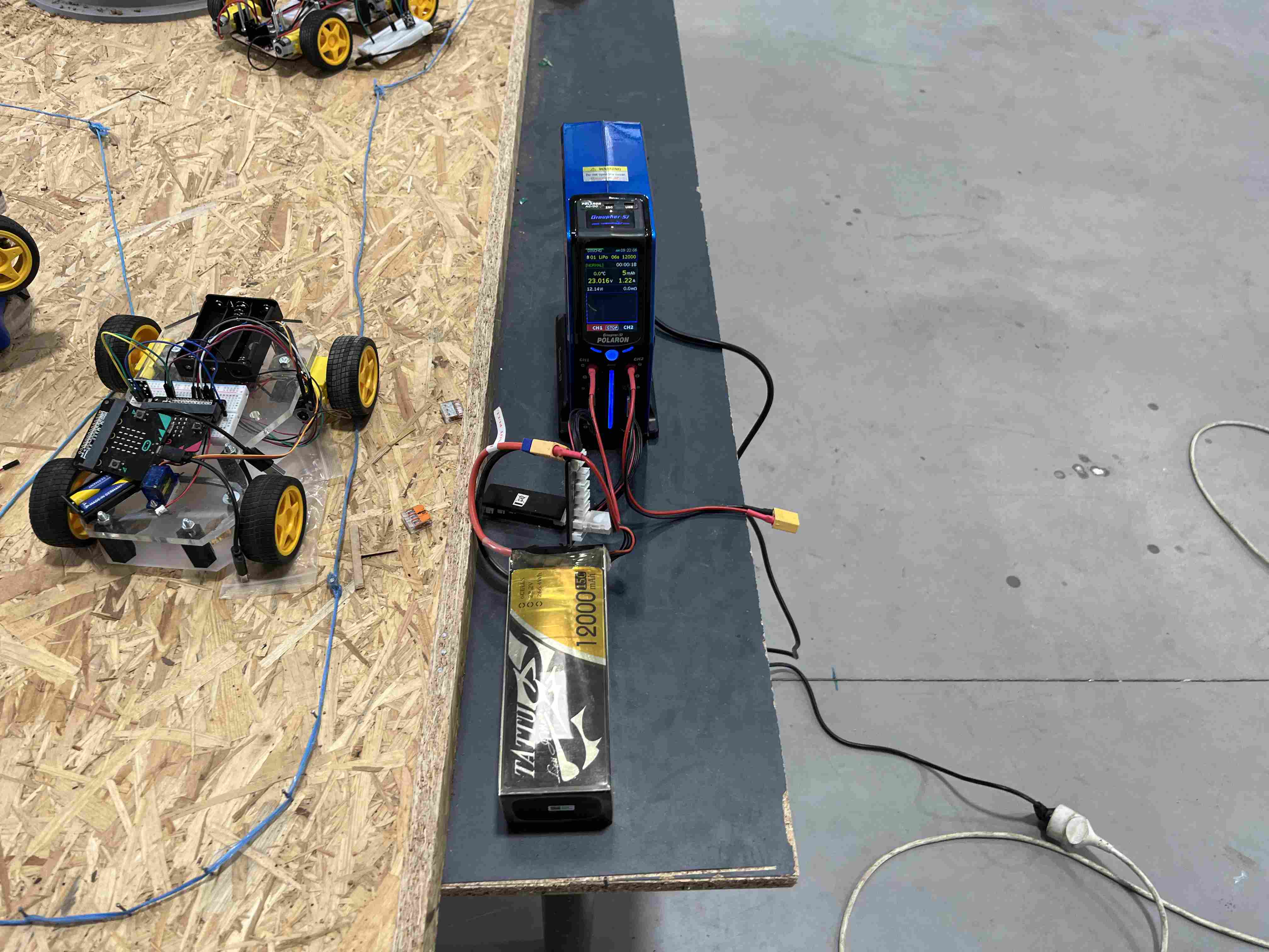
I haven't yet made up my mind about batteries. On the one hand, because prices are extremely high and it's necessary to size their characteristics properly. In order to test, and perhaps as a final solution, I took a drone battery with its charger so that I could use my robot. The drone in which it was housed sputtered, so we first tried charging it to determine whether it was functional or not.
PCB Mounting/ Wire Routing
To have the simplest possible circuit, I tried to put female connectors on my PCB so that I could directly connect my drivers to it. I did the same with the UART for the GPS and with the I2C to have a screen. Adding this involves having more tracks on the PCB but simplifies the connection and use of the different elements.
I still have progress to make regarding wire routing. I am well aware that for now the system is not very optimized. As can be seen from my first mock-up, the result is not very satisfactory, and you can see wires everywhere. Of course, the fact that all these components are concentrated in a small space accentuates this disordered effect, but I plan to further optimize this assembly in my final project by using fasteners to properly group the wires together and arranging the cables so that they have the exact length for each component and do not go in all directions.
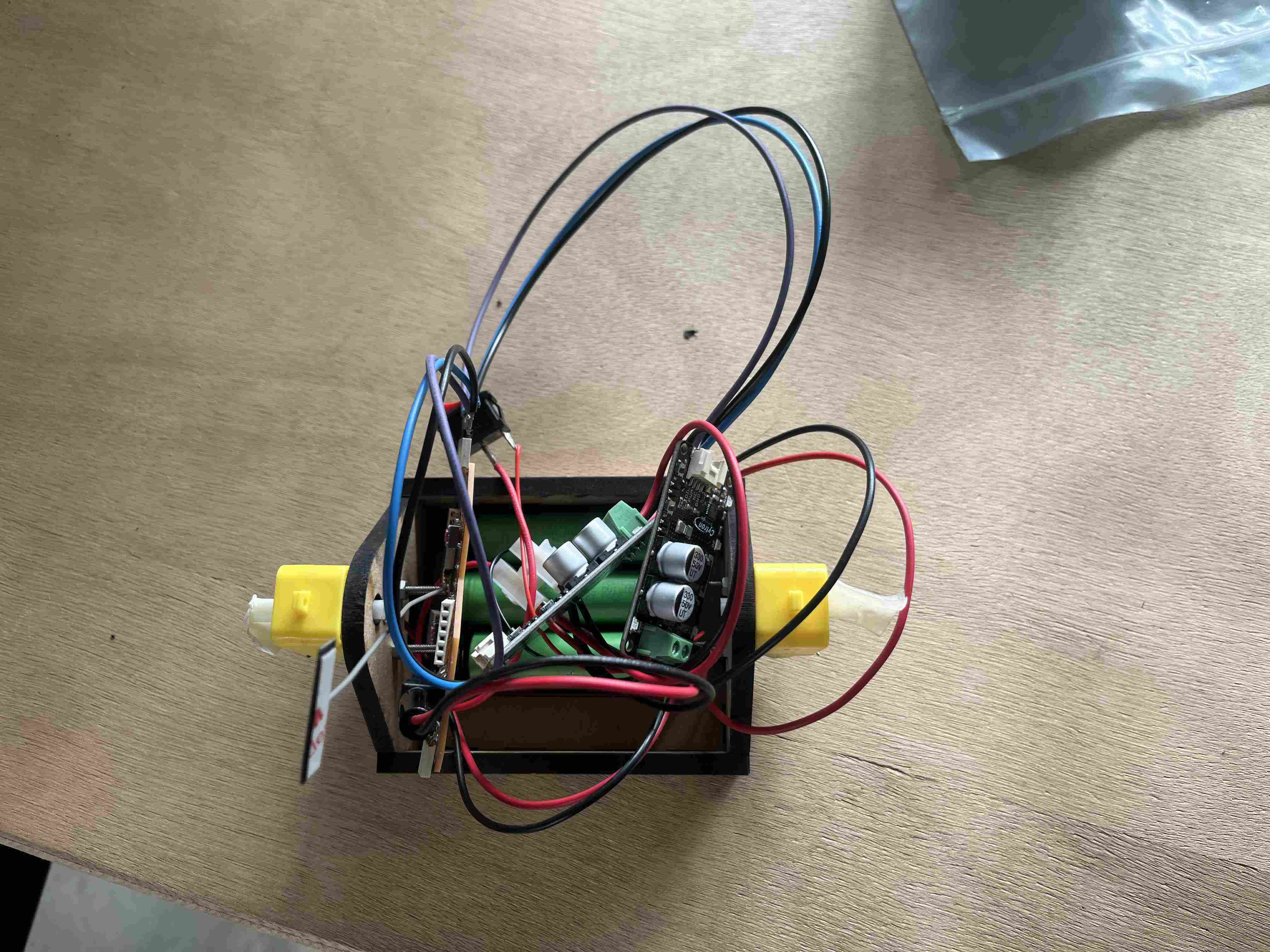
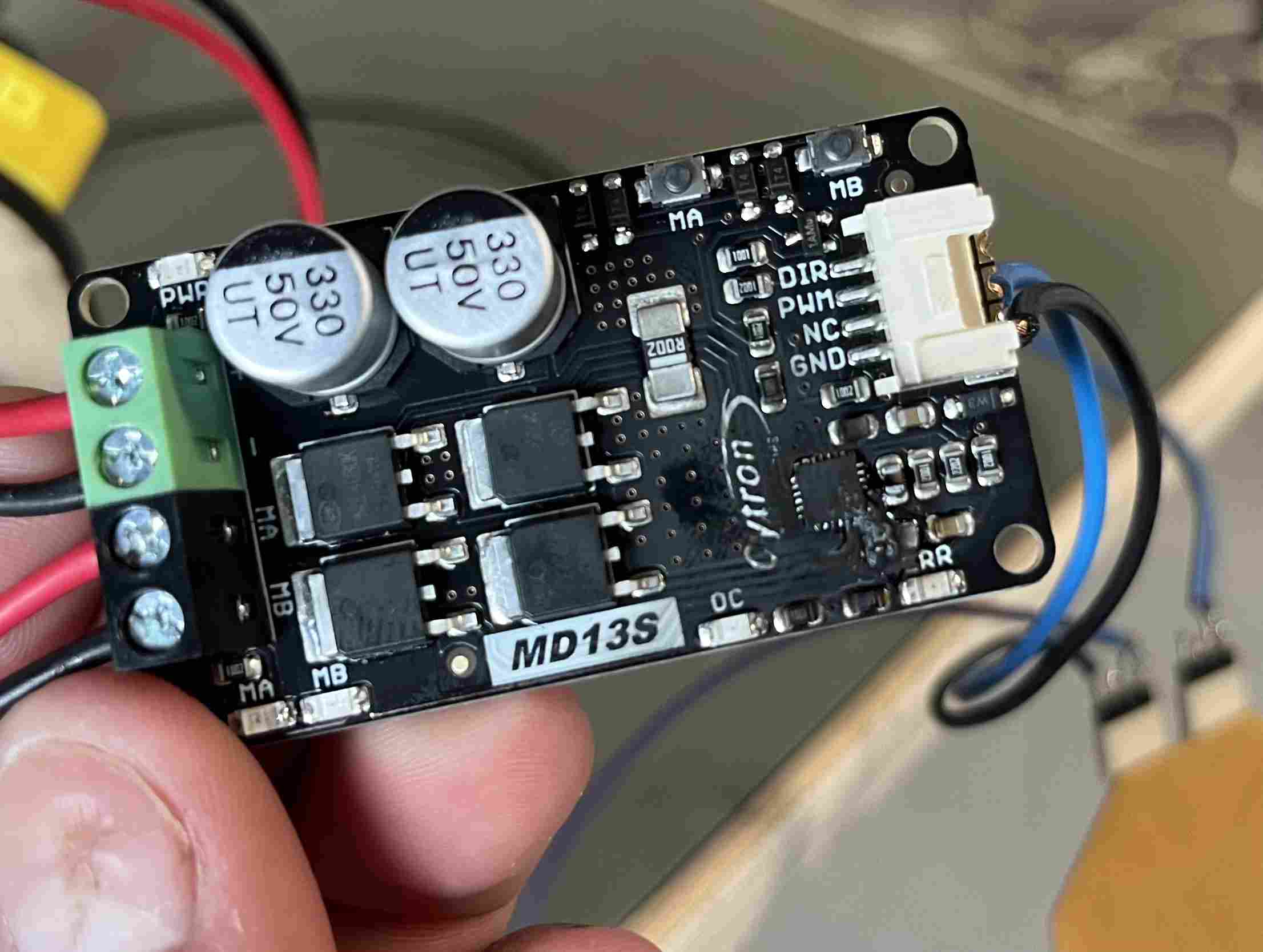
When I tried to test my circuit, all the cables were poorly insulated and touched several places. I probably made a short circuit that burned out one of my two motor drivers.
Of course, from a general point of view, I'm also planning to do a few essential things, such as creating a BOOM to present my project and clearly document the various steps I've taken to get to this end result.
Test with a miniature robot
To test my code, I made a miniature of my robot. To do this, I made a small mdf box, PLA wheels and bars for my MDF wheels. The various designs are shown below in f3D format.
For bars and wheel supports here and for the case here
The motors I used werethis type of motors, the rest of the components are the same I use for my final robot with drivers cytron MD13S, and my PCB to control it all. I had 3 lithium 3.3v batteries connected in series to power my robot. This is what the robot looked like:
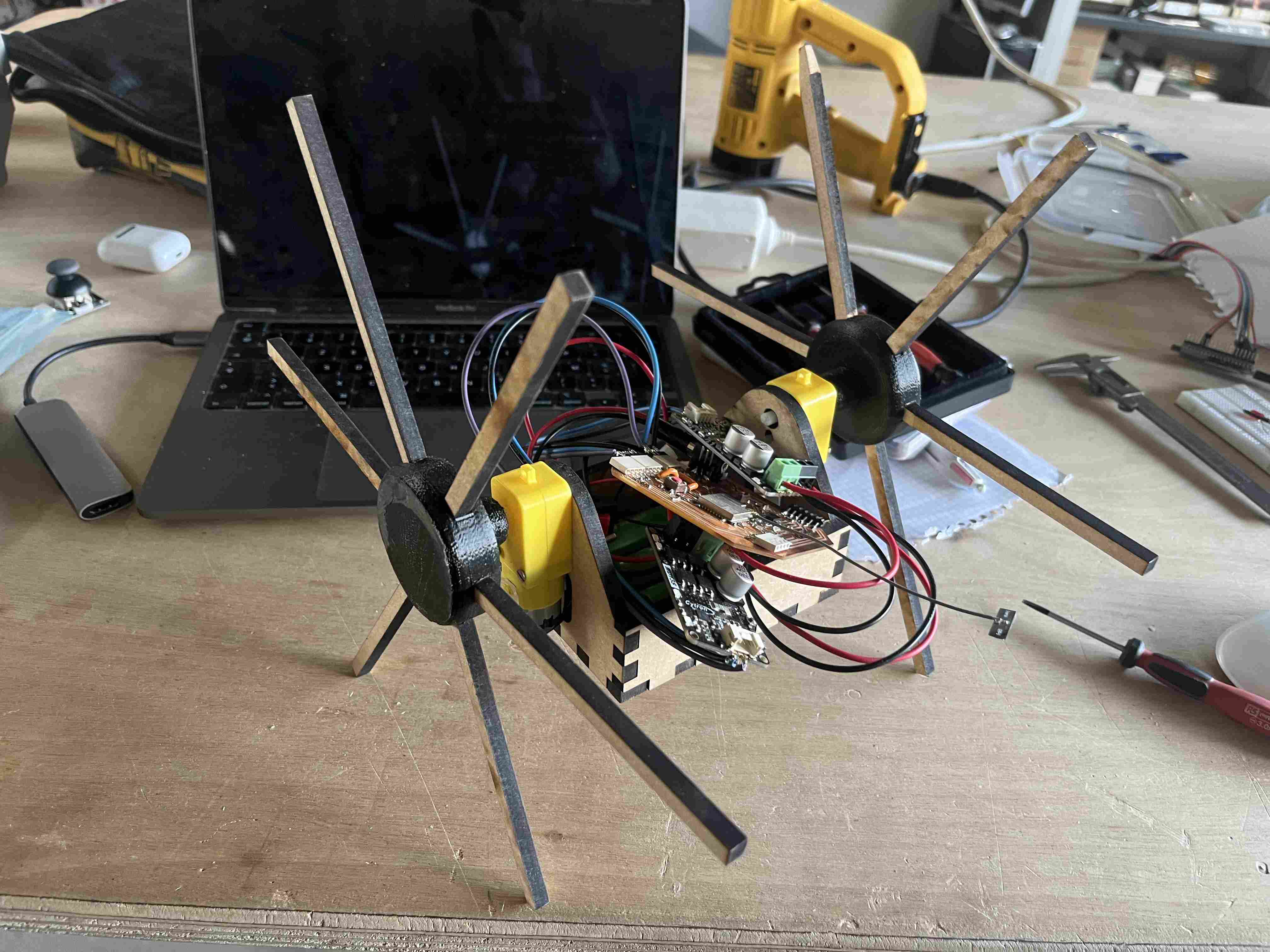
I carried out multiple tests to check my code and whether the different principles worked well. I had good results without the wheels, but when they were fitted, the motors didn't have enough torque. I had put all my electronics in a mess in the box, and this was a bad idea as nothing was well insulated, and during my tests, two wires probably touched, creating a false contact and leading to the ignition of one of the drivers.

Unfortunately, I didn't have time to take a video of my prototype working before burning the driver. As I was nearing the end, and my code was working, I decided not to dwell on the tests with my little robot, but to move on to the realization of my final robot.
Final version
Electronic part
As far as the electronics are concerned, I've made a support plate so I can fix all my components in place and avoid short-circuit problems like I've had in the past. You can find the f3d file here.
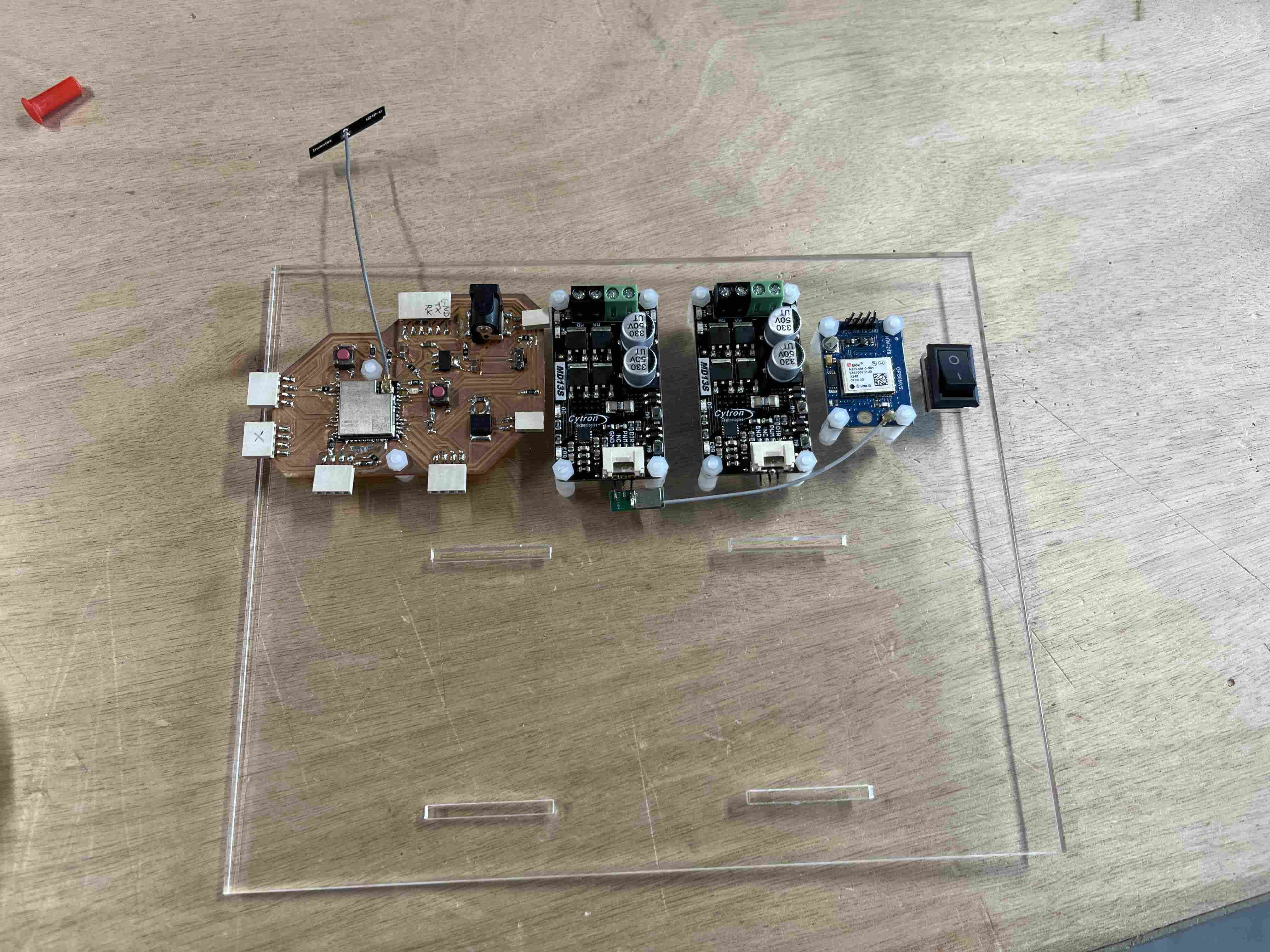
In order to link all the cables together, I made connectors with the right number of poles, which will connect to the drivers on the one hand, and to my PCB on the other. I used riselan to hold the wires so that each set is firmly attached, to avoid having wires running off in all directions.
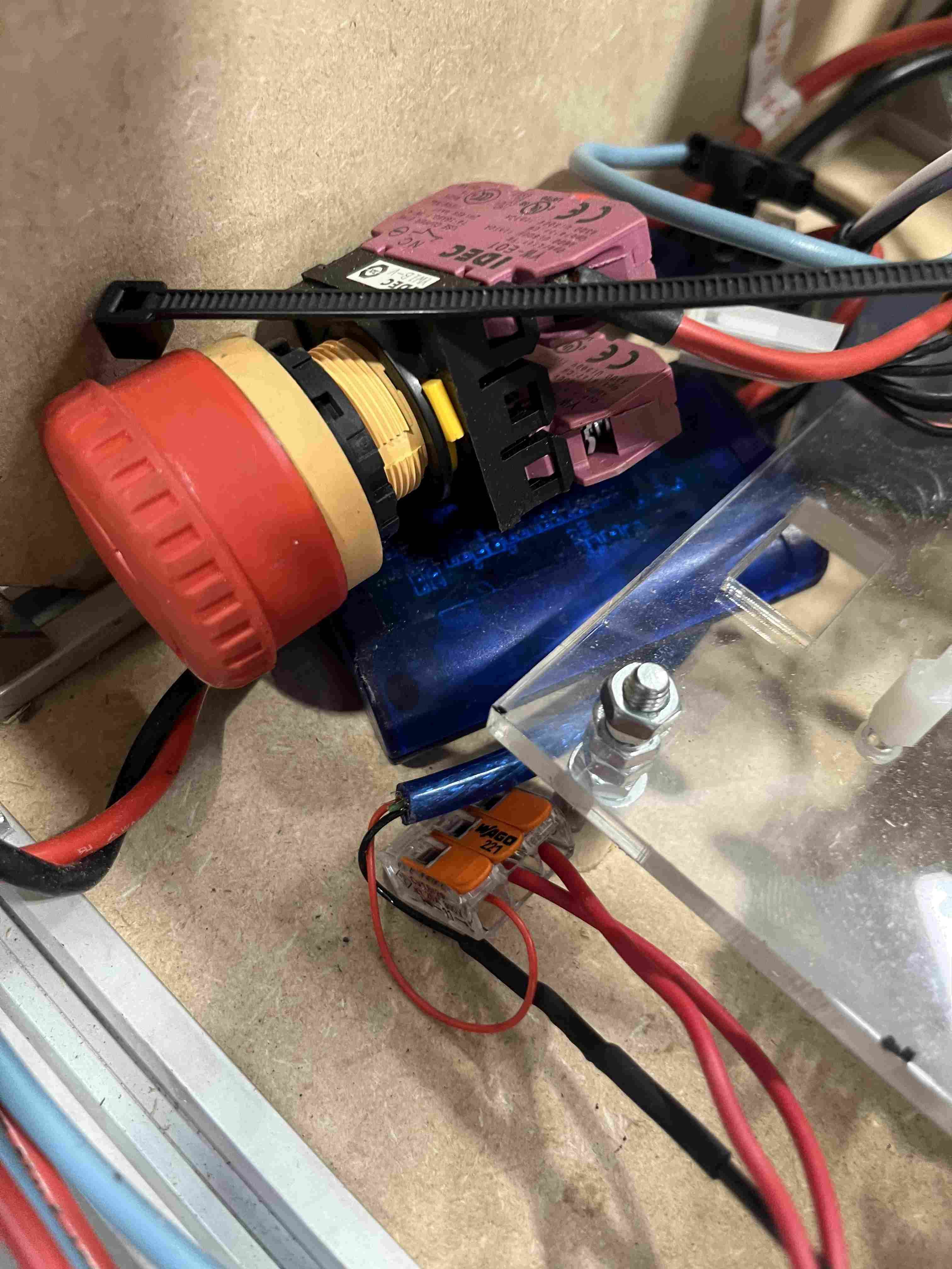
Then I chose to use two different power supplies to simplify voltage management and avoid wasting a lot of energy on a regulator. So I had two electrical installations. The first was the drone battery running on 24V, which I used to power my drivers. I created a circuit with a plug that could be connected to the drone battery, which was then connected to wagos to send the current to the two drivers. I also added an emergency stop button to this circuit, so that the robot could be switched off. I had originally fitted a simple switch, but it probably melted inside because I couldn't turn it off.
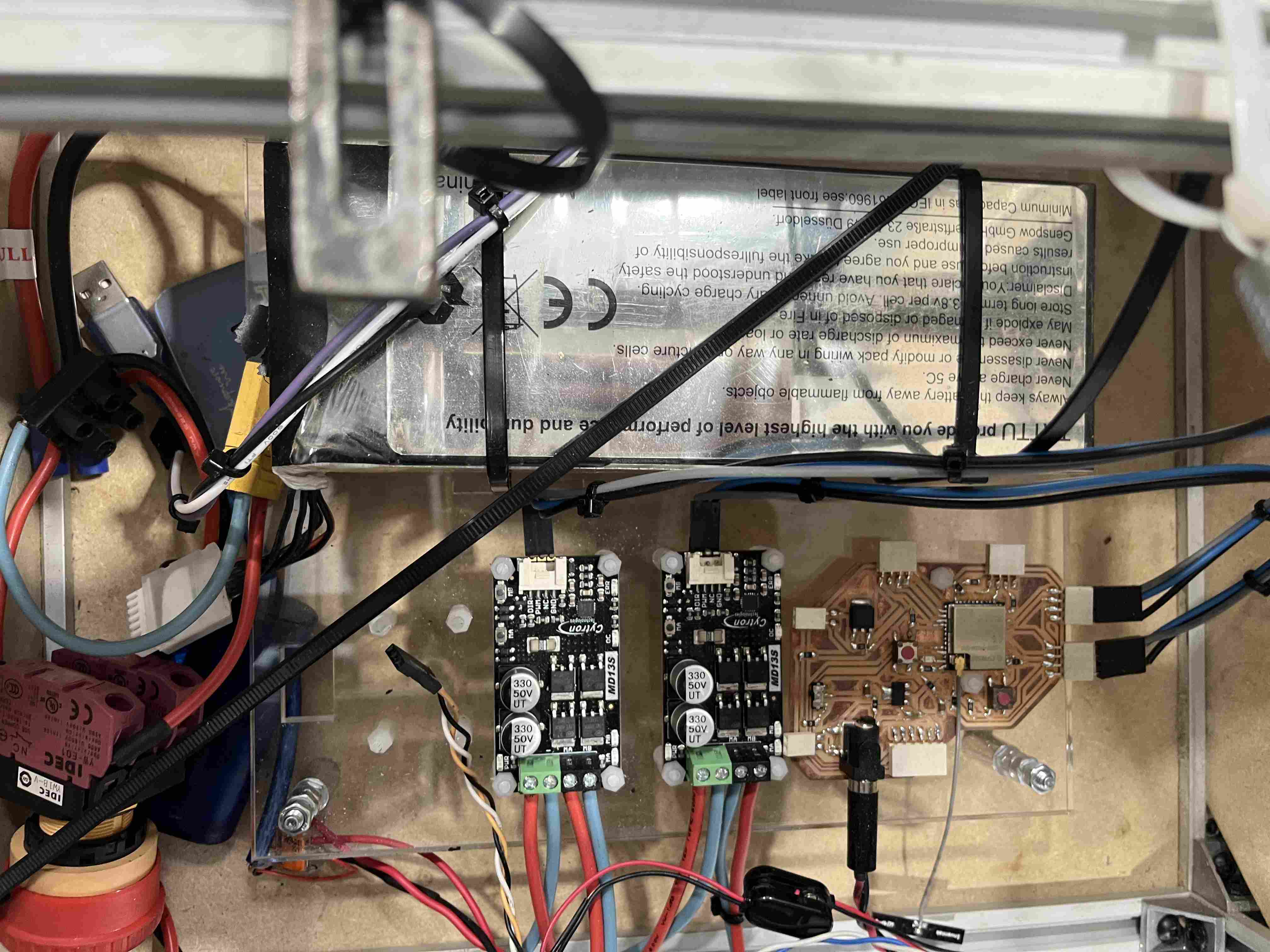
The second power source was an external battery powering my PCB, which is a 5V output, so the regulator simply has to lower the voltage by 1.7V.
Frame section
I then started to make a frame with 20mm profiles assembled with screws and angle brackets, using 6mm MDF which can be fitted into the slots of the profiles, thus eliminating the need for fasteners. To make the MDF pieces, I created a parametric drawing that I was able to adjust according to the different parts by simply modifying the dimensions of the internal gap between my profiles. You can find the file here.
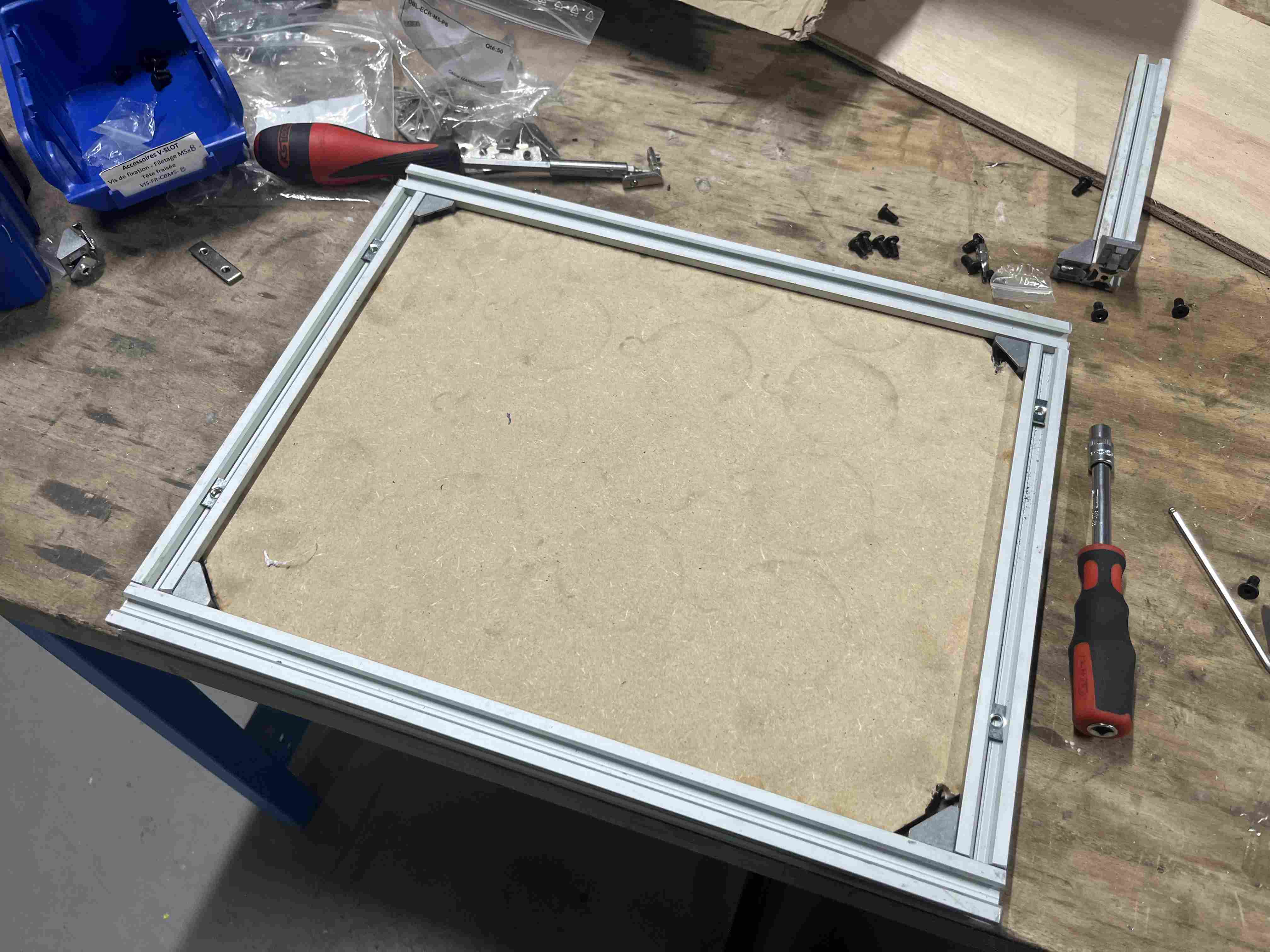
As for the dimensions of the profiles, I made them from scratch, without using CAD, and based on the dimensions of the brackets on my electronics and the length of the axles I used to fit the wheels, which measured a total of 27cm. As for the length of my profiles, they are as follows:
| Length | 389 mm |
|---|---|
| Width | 269 mm |
| Height | 171 mm |
| Motor and bearing crossbar | 349 mm |
I'd like to point out that the width and length dimensions are the same on both the bottom and the top of the frame. I fastened the top and bottom frames with self-drilling screws and then assembled the rest with hammer nuts, angle brackets and 8mm M5 pan-head screws.
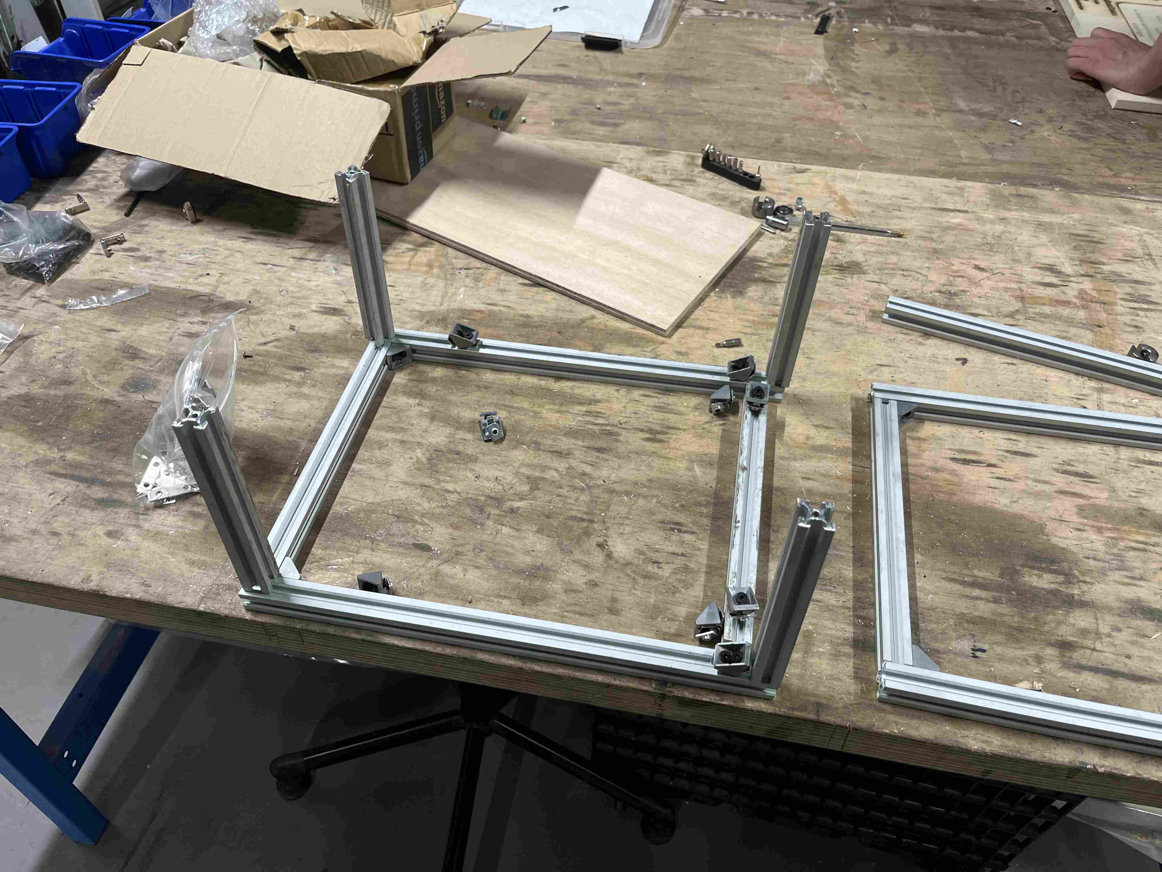
To support my motors, I made a support out of 3mm steel. You can find the different DXF files below:
- frame side section here
-the part where the motor is mounted here
-reinforcing brackets on the sides here.
You can also find the f3D file here.
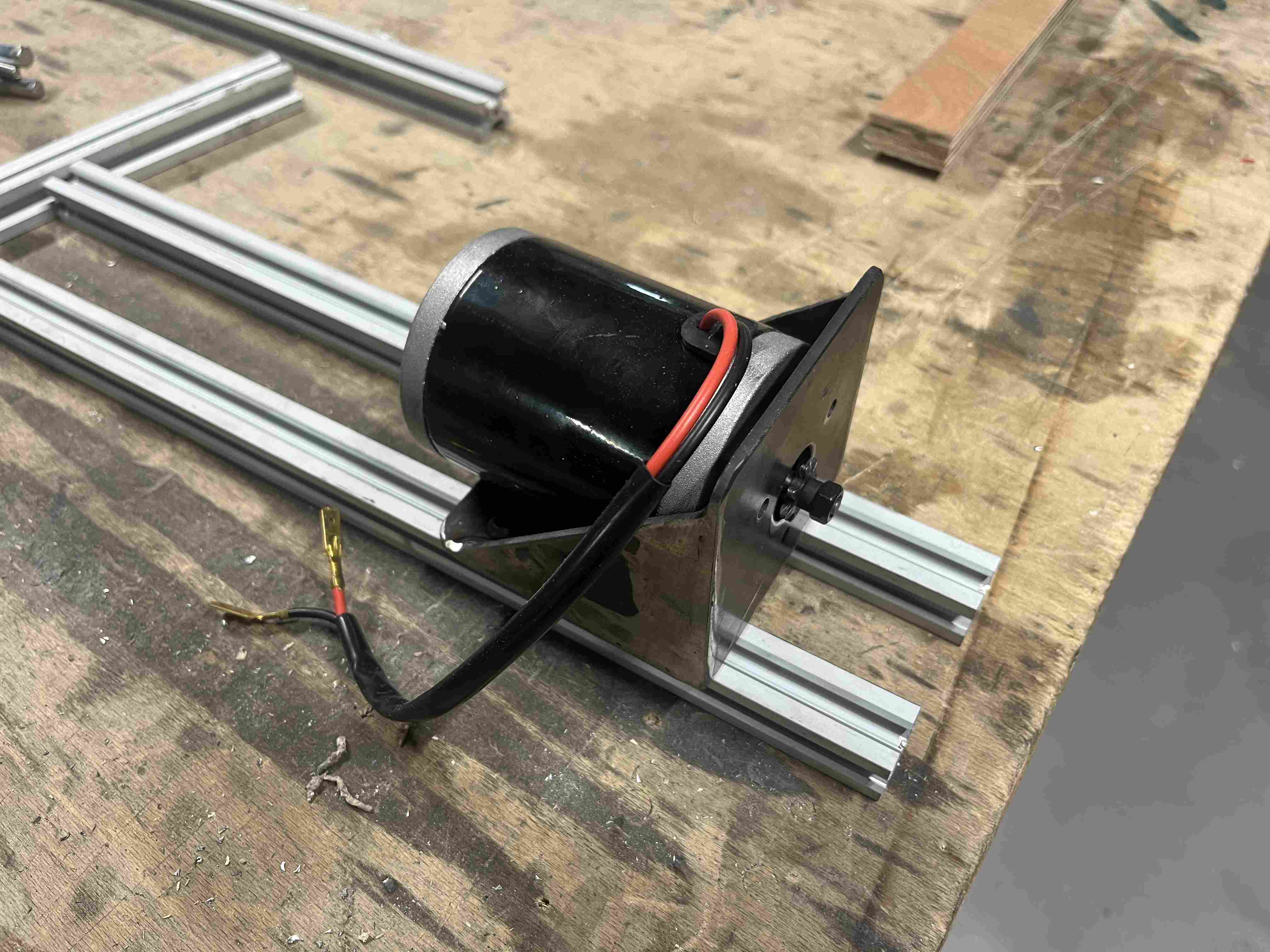
You may notice that on the various files, the hole size is 1.5mm and not the size of an M5 screw, i.e. 5mm. The diameter used makes it possible to simply point the various holes with the plasma cutter and then drill them more cleanly with a drill bit, since plasma cutting, although very useful, doesn't give a perfect result.
The axes
Having moved my drive part away from my wheel part, I made an axle system with bearings to hold it and at the end of which the wheels were fixed.
As far as the axle part was concerned, at Agrilab we used stainless steel bars 10mm in diameter and 27cm long. The advantage of these bars was that they were sufficiently rigid and had bearings that fitted perfectly into them, with an external diameter of 30mm. A locking system was integrated on both sides of the bearings to prevent them from slipping out of place. puissent se déplacer sur l'axe.
Bearings
As far as the bearings were concerned, I had to go back to the drawing board several times. The first solution I considered was to print them in nylon reinforced with carbon fiber. At agrilab, we have a printer Markforged mark two which is capable of printing these materials. After many attempts, the results were always disappointing and I always had my nozzle clogging up, stopping the print. Nylon is a very complex material to print and doesn't tolerate humidity very well, so I imagine that it had been poorly preserved, which made printing it so disappointing.
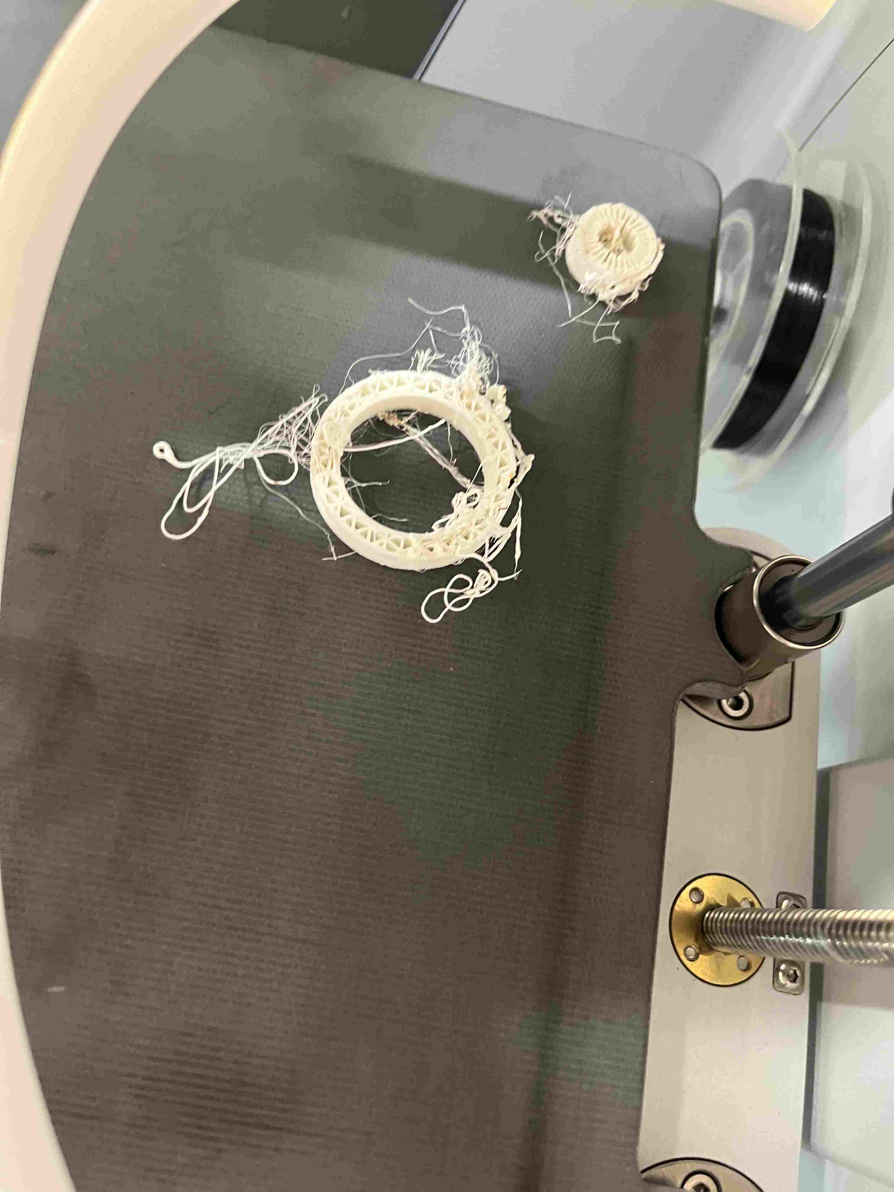
The second solution I envisaged was to make PETG bearings. I therefore used the prusa printer, using the parameters recommended in this website and the results were quite satisfactory. In the first version, I'd put the holes on my print so as not to have to drill them, but when I printed them, they didn't fit properly and weren't centered. On top of that, the pasta on the sides didn't fit the tray. So I made a second attempt by adding glue to my tray and removing the holes from my design, and the result of the printing was much more satisfactory. The final design is here
However, when I tried to drill the holes manually with the drill press, I found that my prints cracked and were therefore not resistant to drilling. Despite the use of PETG, reputed to be stronger than PLA, the choice of 3D printing was not a good solution.
The last solution tested, and the one finally chosen for the final project, was the manufacture of steel bearings, stronger than plastic, on which the bearings are directly welded. To make these bearings, I used 5mm-thick pieces of steel. I made a 3D model, which you can find here. here. I made a large daylight on the mounting brackets to adjust the position of the bearings from front to rear in relation to the chassis, so as to be able to adjust the transmission tension in this way. The two parts making up the bearing were sanded and MIG welded, then the bearings were welded into the bearing.
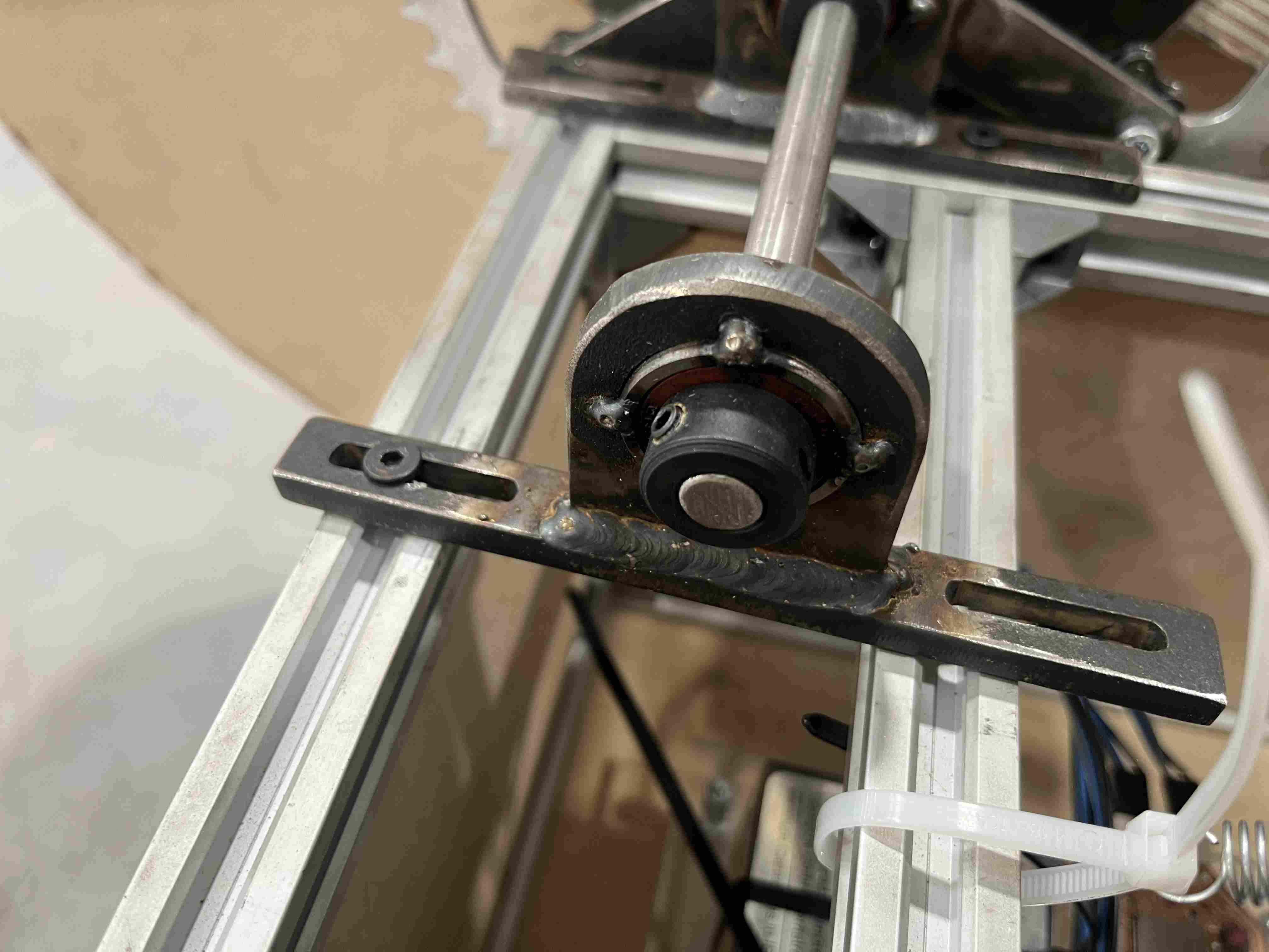
Training
I knew when I bought the motors that they wouldn't have the torque to drive such large wheels, so I had to find a solution to reduce the force exerted by them. At first, I thought of creating a gearbox that I could adapt to my motor, but I was discouraged by the complexity of the thing and the high risk of breakage with 3D-printed parts. So I tried to multiply the force using bicycle parts. I went to a store that sold bicycle parts and bought two pinions of the smallest size (11 teeth) and two crowns of the largest size I could find (53 teeth). Using this method allowed me to reduce the force, but only with a ratio of 4.8, which is still far too low.
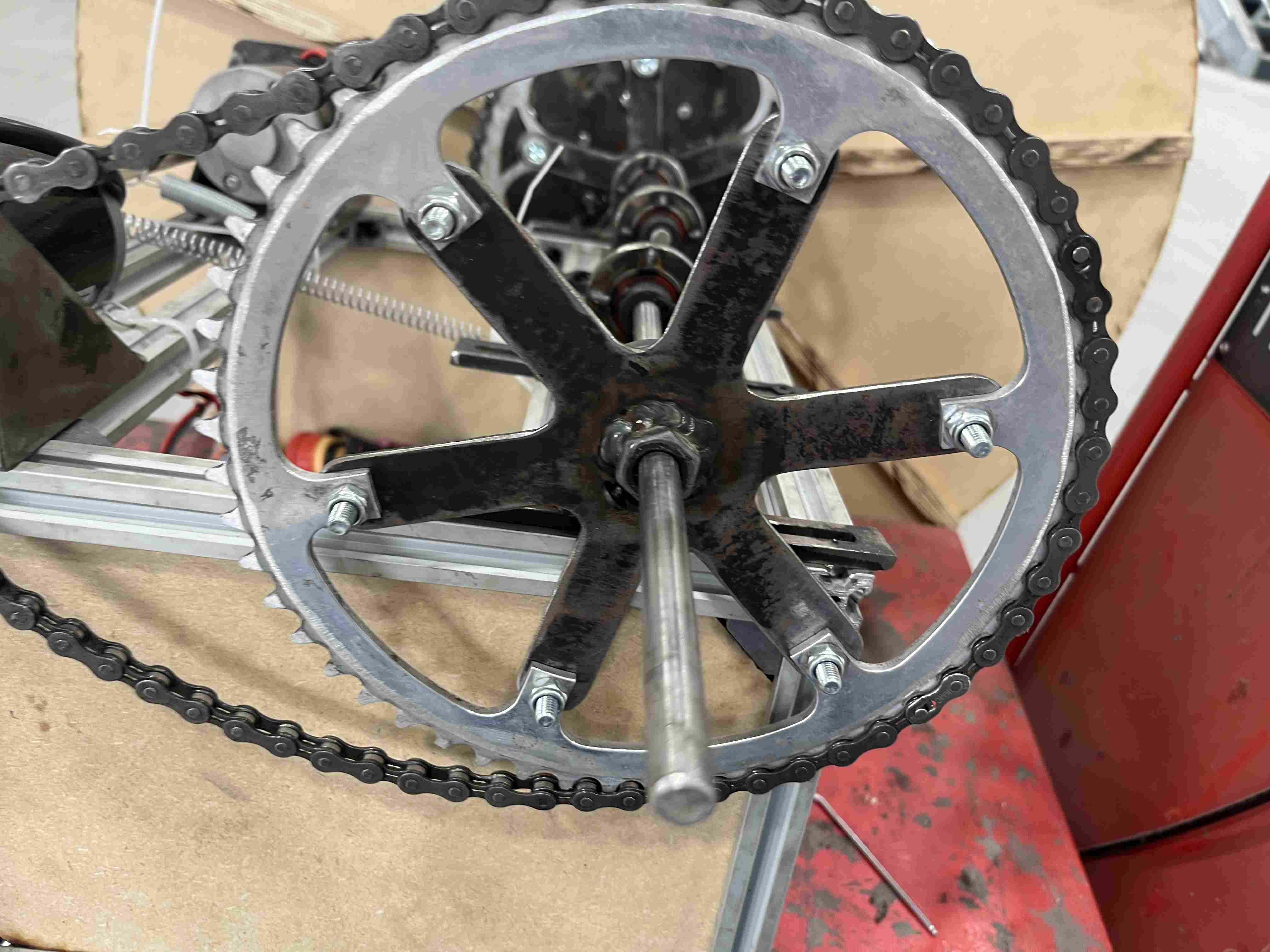
My motor already had a drive pinion, but in a very small standard size that didn't correspond at all to a bicycle standard. The original pinion already fitted to the motor had a flat metre that provided a good drive. To avoid having to create a part with a flat metre like the original pinion, I simply used the plasma cutter to create a washer corresponding to the inside diameter of the pinion, with a central hole slightly larger than the axis of my motor. As a result, I was able to weld my bike pinion to the washer, as well as the netrainer pinion, so as to make the link between the two. You'll find here the f3d file of the puck.
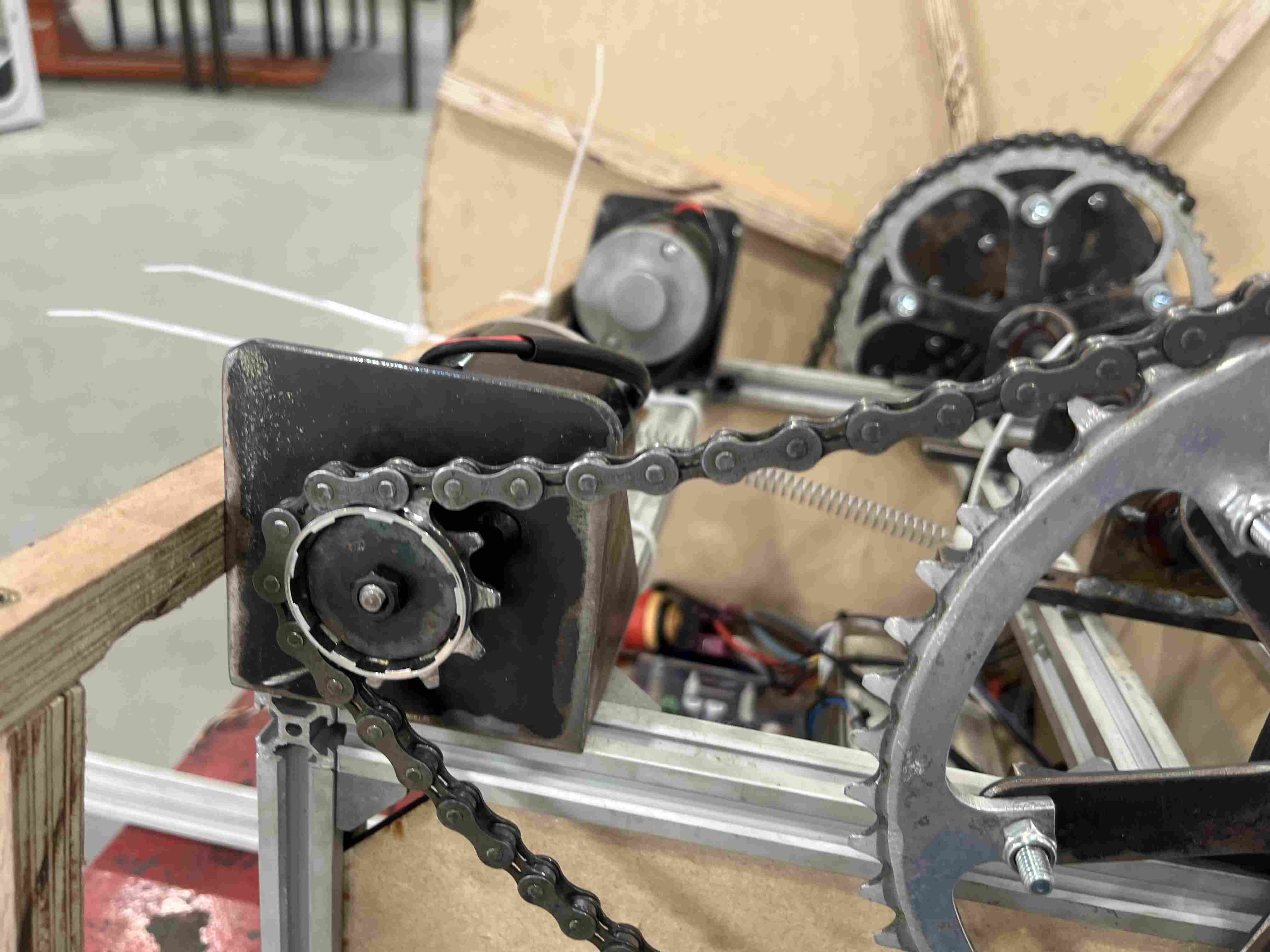
As for the wheel part, I also made a steel adapter to link the bicycle crowns to my wheel axles. To do this, I created a fused part that mates with the bike's original mounting holes and is drilled in the center to allow the motor axle to pass through.
I also used a nut drilled and tapped on the side to maintain good adhesion between the wheel arch and the ring gear. Once the nut was primed, all that remained was to weld it onto the adapter.
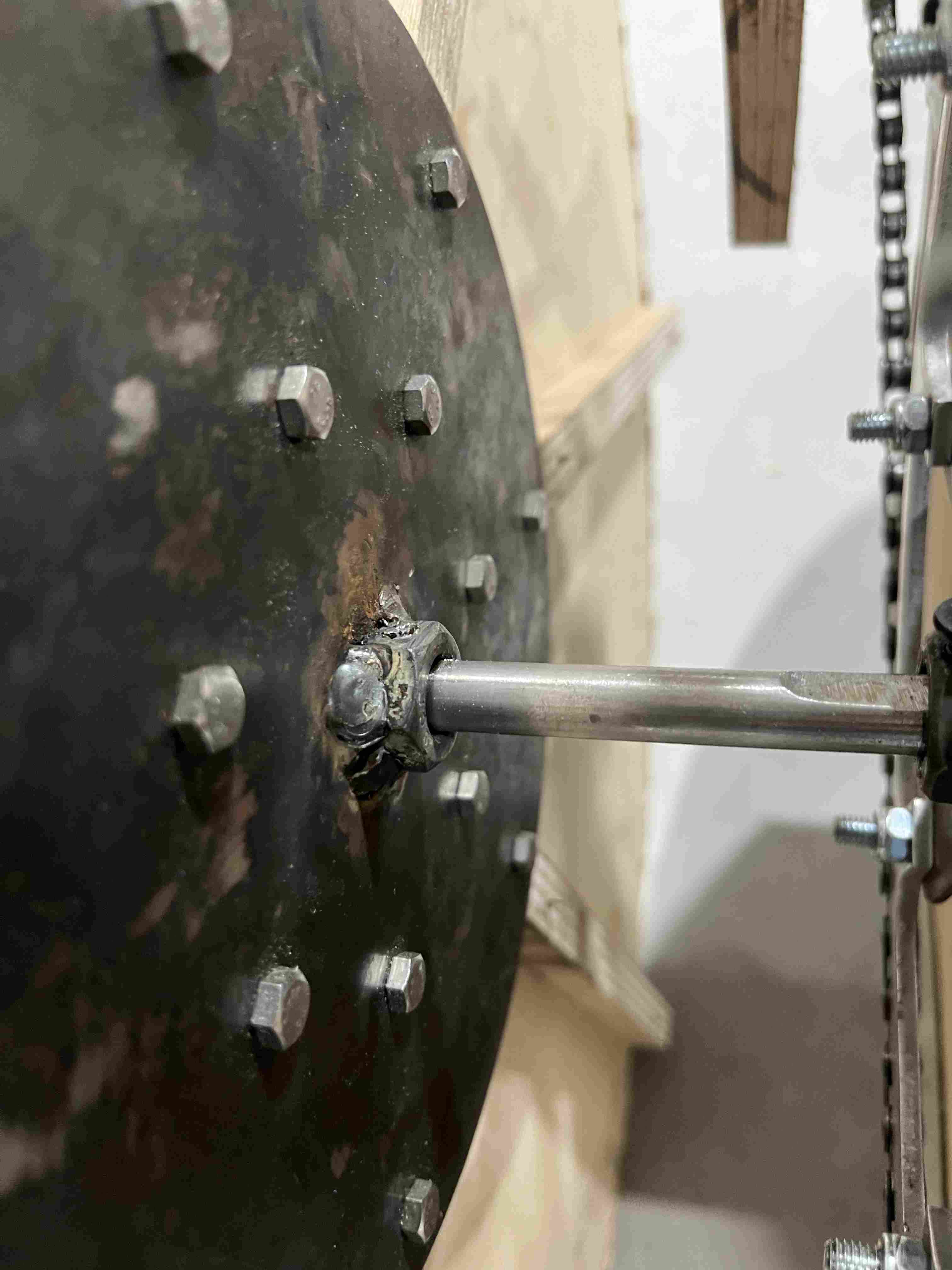
Having bought my crowns in a second-hand store, I couldn't find two identical crowns, so they have the same properties (number of teeth, diameters) but they don't have the same fixings, so I had to create two different designs, the first here and the second here.
In order to connect my crowns to the pinions, all I needed was a chain to make the trnasmission. The chain would sometimes go off the rails, and this proved to be quite dangerous, so I added a piece of wood held in place by springs. It's very poorly made and not worth a real turnbuckle, but it's functional and considerably reduces the moments when the chain will go off the rails.
Once I'd finalized my drive system, I was able to test it and the crown wheels were turning around the axles because the presence of the nut wasn't enough. So I used a grinder to sand down my axles to create a flat surface so that my nuts could make good contact, and it worked.
Wheels
To create my wheels, I first created a parametric fusion design so that I could simply modify either the length of my poles or the number on the wheel, or other parameters. You can download the f3D file here. I then plasma cut my patinas from 3mm steel. I made a mistake in choosing to cut my two plates directly and identically on the plasma cutter. The machine is reliable, but not perfect. The punching holes I made, once drilled, didn't fall exactly opposite each other on the two different plates, so I had to make a second drilling by clamping them together so that all the holes fell opposite each other. When I made the second wheel, I only drilled one plate, and on the second one I only drilled the hole in the center where the axle is supposed to go through, so I could drill both plates at once and get holes that were right opposite each other.
To hold my plates on the axles, I added nuts to the center hole, drilled them and tapped them across so I could screw in an M5 screw. The nuts were then welded to the plate.
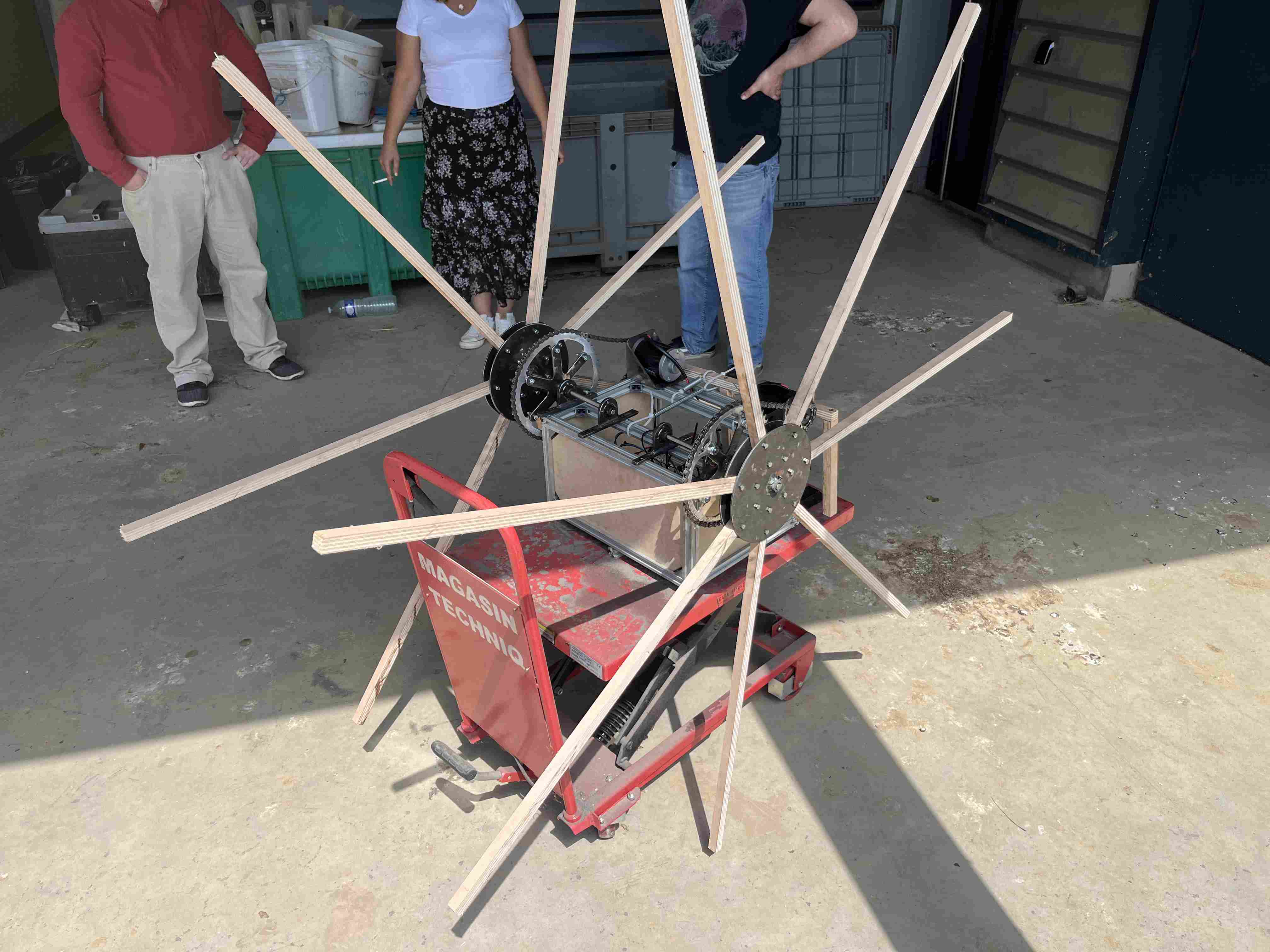
Once my turntables were finished, I turned my attention to the construction of the poles, with various possibilities open to me, starting with different materials. I mainly chose wood or aluminum for their solidity and lightness. For the first version, I chose wood because it's much less expensive than aluminum.
To make the poles, I cut 18mm-thick plywood into 18mm-wide sections using the circular saw. Once all the poles had been cut, I used the drill press to make holes for the screws.
Robot control
To control my robot, I used the communication protocol ESPNOW. With the help of a ESP32 Dev KitC v4 which I had connected to a Joysick, I transmitted the information to my PCB, which also worked with an esp32 microcontroller. In this way, I was able to control its progress like a remote-controlled robot. The robot was initially intended to have an automatic mode in addition to the manual mode, but given the difficulties encountered in developing the robot, I couldn't go as far as making the manual mode a reality.
Master
In our context, the master will be controlled by the esp32 dev kit. Connected to a joystick, it will continuously send joystick positioning information to our master. We made the following connections:
| Pin ESP32 | GND | 5V | 34 | 35 |
|---|---|---|---|---|
| Pin joystick | GN | Vin/5V | 34 | 35 |
The code I then used was the one below, and you can see how I made it during my week. Networking and communication.
#include "esp_now.h"
#include "WiFi.h"
#include "esp_wifi.h" // only for esp_wifi_set_channel()


// Global copy of slave
esp_now_peer_info_t slave;
#define CHANNEL 1
#define PRINTSCANRESULTS 0
#define DELETEBEFOREPAIR 0
//uint8_t broadcastAddress[] = {0xC4, 0xDE, 0xE2, 0xC0, 0x7E, 0xB9}
uint8_t broadcastAddress[] = {0xAC, 0x67, 0xB2, 0x75, 0x31, 0xD5};

//uint8_t data = 0; //valeur envoyee
//uint8_t data[3] = {0, 0, 0}; //valeur envoyee
const int buttonPin = 2;
const int axisY = 34;
const int axisX = 35;
int buttonState = 0;
int button;
int avance=0;
int direction=0;
int test=0;
typedef struct joystick_data {
  int button;
  int axisY;
  int axisX;
} joystick_data;


// Init ESP Now with fallback
void InitESPNow() {
  WiFi.disconnect();
  if (esp_now_init() == ESP_OK) {
    Serial.println("ESPNow Init Success");
  }
  else {
    Serial.println("ESPNow Init Failed");
    // Retry InitESPNow, add a counte and then restart?
    // InitESPNow();
    // or Simply Restart
    ESP.restart();
  }
}

// Scan for slaves in AP mode
void ScanForSlave() {
  int16_t scanResults = WiFi.scanNetworks(false, false, false, 300, CHANNEL); // Scan only on one channel
  // reset on each scan
  bool slaveFound = 0;
  memset(&slave, 0, sizeof(slave));

  Serial.println("");
  if (scanResults == 0) {
    Serial.println("No WiFi devices in AP Mode found");
  } else {
    Serial.print("Found "); Serial.print(scanResults); Serial.println(" devices ");
    for (int i = 0; i < scanResults; ++i) {
      // Print SSID and RSSI for each device found
      String SSID = WiFi.SSID(i);
      int32_t RSSI = WiFi.RSSI(i);
      String BSSIDstr = WiFi.BSSIDstr(i);

      if (PRINTSCANRESULTS) {
        Serial.print(i + 1);
        Serial.print(": ");
        Serial.print(SSID);
        Serial.print(" (");
        Serial.print(RSSI);
        Serial.print(")");
        Serial.println("");
      }
      delay(10);
      // Check if the current device starts with `Slave`
      if (SSID.indexOf("Slave") == 0) {
        // SSID of interest
        Serial.println("Found a Slave.");
        Serial.print(i + 1); Serial.print(": "); Serial.print(SSID); Serial.print(" ["); Serial.print(BSSIDstr); Serial.print("]"); Serial.print(" ("); Serial.print(RSSI); Serial.print(")"); Serial.println("");
        // Get BSSID => Mac Address of the Slave
        int mac[6];
        if ( 6 == sscanf(BSSIDstr.c_str(), "%x:%x:%x:%x:%x:%x",  &mac[0], &mac[1], &mac[2], &mac[3], &mac[4], &mac[5] ) ) {
          for (int ii = 0; ii < 6; ++ii ) {
            slave.peer_addr[ii] = (uint8_t) mac[ii];
          }
        }

        slave.channel = CHANNEL; // pick a channel
        slave.encrypt = 0; // no encryption

        slaveFound = 1;
        // we are planning to have only one slave in this example;
        // Hence, break after we find one, to be a bit efficient
        break;
      }
    }
  }

  if (slaveFound) {
    Serial.println("Slave Found, processing..");
  } else {
    Serial.println("Slave Not Found, trying again.");
  }

  // clean up ram
  WiFi.scanDelete();
}

// Check if the slave is already paired with the master.
// If not, pair the slave with master
bool manageSlave() {
  if (slave.channel == CHANNEL) {
    if (DELETEBEFOREPAIR) {
      deletePeer();
    }

    Serial.print("Slave Status: ");
    // check if the peer exists
    bool exists = esp_now_is_peer_exist(slave.peer_addr);
    if ( exists) {
      // Slave already paired.
      Serial.println("Already Paired");
      return true;
    } else {
      // Slave not paired, attempt pair
      esp_err_t addStatus = esp_now_add_peer(&slave);
      if (addStatus == ESP_OK) {
        // Pair success
        Serial.println("Pair success");
        return true;
      } else if (addStatus == ESP_ERR_ESPNOW_NOT_INIT) {
        // How did we get so far!!
        Serial.println("ESPNOW Not Init");
        return false;
      } else if (addStatus == ESP_ERR_ESPNOW_ARG) {
        Serial.println("Invalid Argument");
        return false;
      } else if (addStatus == ESP_ERR_ESPNOW_FULL) {
        Serial.println("Peer list full");
        return false;
      } else if (addStatus == ESP_ERR_ESPNOW_NO_MEM) {
        Serial.println("Out of memory");
        return false;
      } else if (addStatus == ESP_ERR_ESPNOW_EXIST) {
        Serial.println("Peer Exists");
        return true;
      } else {
        Serial.println("Not sure what happened");
        return false;
      }
    }
  } else {
    // No slave found to process
    Serial.println("No Slave found to process");
    return false;
  }
}

void deletePeer() {
  esp_err_t delStatus = esp_now_del_peer(slave.peer_addr);
  Serial.print("Slave Delete Status: ");
  if (delStatus == ESP_OK) {
    // Delete success
    Serial.println("Success");
  } else if (delStatus == ESP_ERR_ESPNOW_NOT_INIT) {
    // How did we get so far!!
    Serial.println("ESPNOW Not Init");
  } else if (delStatus == ESP_ERR_ESPNOW_ARG) {
    Serial.println("Invalid Argument");
  } else if (delStatus == ESP_ERR_ESPNOW_NOT_FOUND) {
    Serial.println("Peer not found.");
  } else {
    Serial.println("Not sure what happened");
  }
}

void setup() {
  Serial.begin(115200);
  //Set device in STA mode to begin with
  WiFi.mode(WIFI_STA);
  esp_wifi_set_channel(CHANNEL, WIFI_SECOND_CHAN_NONE);
  Serial.println("ESPNow/Basic/Master Example");
  // This is the mac address of the Master in Station Mode
  Serial.print("STA MAC: "); Serial.println(WiFi.macAddress());
  Serial.print("STA CHANNEL "); Serial.println(WiFi.channel());
  // Init ESPNow with a fallback logic
  InitESPNow();
  // Once ESPNow is successfully Init, we will register for Send CB to
  // get the status of Trasnmitted packet
 //esp_now_register_send_cb(OnDataSent);
}

void loop() {
  // In the loop we scan for slave
  ScanForSlave();
  // If Slave is found, it would be populate in `slave` variable
  // We will check if `slave` is defined and then we proceed further
  if (slave.channel == CHANNEL) { // check if slave channel is defined
    // `slave` is defined
    // Add slave as peer if it has not been added already
    bool isPaired = manageSlave();
    if (isPaired) {
      // pair success or already paired
      // Send data to device
      sendData();
    } else {
      // slave pair failed
      Serial.println("Slave pair failed!");
    }
  }
  //else {
    // No slave found to process
  //}
joystick_data test;
    button=buttonPin;
    avance=analogRead(axisX);
    direction=analogRead(axisY);


  //// wait for 3seconds to run the logic again
  delay(100);

//  buttonState = digitalRead(buttonPin);
//  if (buttonState == HIGH) {
//    data[0] = 1;
//  }


}

// send data
void sendData() {
  const uint8_t *peer_addr = slave.peer_addr;
//  joystick_data test;
//  avance=analogRead(axisX);
//  direction=analogRead(axisY);
  Serial.print("Sending: "); Serial.println(test);
  //esp_err_t result = esp_now_send(peer_addr, (uint8_t *) &test.x, sizeof(test.x));//&data, sizeof(data));
  esp_err_t result = esp_now_send(
    broadcastAddress,
    (uint8_t *) &test,
    sizeof(joystick_data));

  Serial.print("Send Status: ");
  if (result == ESP_OK) {
    Serial.println("Success");
  //  test_struct = 0;
  } else if (result == ESP_ERR_ESPNOW_NOT_INIT) {
    // How did we get so far!!
    Serial.println("ESPNOW not Init.");
  } else if (result == ESP_ERR_ESPNOW_ARG) {
    Serial.println("Invalid Argument");
  } else if (result == ESP_ERR_ESPNOW_INTERNAL) {
    Serial.println("Internal Error");
  } else if (result == ESP_ERR_ESPNOW_NO_MEM) {
    Serial.println("ESP_ERR_ESPNOW_NO_MEM");
  } else if (result == ESP_ERR_ESPNOW_NOT_FOUND) {
    Serial.println("Peer not found.");
  } else {
    Serial.println("Not sure what happened");
  }
  delay(100);
}

// callback when data is sent from Master to Slave
void OnDataSent(const uint8_t *mac_addr, esp_now_send_status_t status) {
  char macStr[18];
  snprintf(macStr, sizeof(macStr), "%02x:%02x:%02x:%02x:%02x:%02x",
           mac_addr[0], mac_addr[1], mac_addr[2], mac_addr[3], mac_addr[4], mac_addr[5]);
  Serial.print("Last Packet Sent to: "); Serial.println(macStr);
  Serial.print("Last Packet Send Status: "); Serial.println(status == ESP_NOW_SEND_SUCCESS ? "Delivery Success" : "Delivery Fail");
   Serial.println(test);
   delay(1000);
}
Slave
The slave, the esp32, is located inside the robot and receives and interprets the data sent by the joystick to control the robot's progress. The connections are as follows:
| Pin ESP32 | 26 | 25 | 33 | 32 |
|---|---|---|---|---|
| Pin drivers | Direction driver 1 | PWM drvier 1 | Direction driver 2 | PWM drvier 2 |
Once these pins are connected, simply upload the following code to esp32 SLAVE.
#include "esp_now.h"
#include "WiFi.h"
// Define pins for steering control
const int DIR1 = 26;
const int PWM1_PIN = 25;
const int DIR2 = 33;
const int PWM2_PIN = 32;
int button;
int avance_value = 0;
int direction_value = 0;

int test=0;
typedef struct joystick_data {
  int button;//première ligne du struct n'est pas lu est attribue directement la valeur 0
  int avance;
  int direction;
} joystick_data;

#define CHANNEL 1

// Init ESP Now with fallback
void InitESPNow() {
  WiFi.disconnect();
  if (esp_now_init() == ESP_OK) {
    Serial.println("ESPNow Init Success");
  }
  else {
    Serial.println("ESPNow Init Failed");
    // Retry InitESPNow, add a counte and then restart?
    // InitESPNow();
    // or Simply Restart
    ESP.restart();
  }
}

// config AP SSID
void configDeviceAP() {
  const char *SSID = "Slave_1";
  bool result = WiFi.softAP(SSID, "Slave_1_Password", CHANNEL, 0);
  if (!result) {
    Serial.println("AP Config failed.");
  } else {
    Serial.println("AP Config Success. Broadcasting with AP: " + String(SSID));
    Serial.print("AP CHANNEL "); Serial.println(WiFi.channel());
  }
}

void setup() {
  Serial.begin(115200);
  Serial.println("ESPNow/Basic/Slave Example");
  //Set device in AP mode to begin with
  WiFi.mode(WIFI_AP);
  // configure device AP mode
  configDeviceAP();
  // This is the mac address of the Slave in AP Mode
  Serial.print("AP MAC: "); Serial.println(WiFi.softAPmacAddress());
  // Init ESPNow with a fallback logic
  InitESPNow();
  // Once ESPNow is successfully Init, we will register for recv CB to
  // get recv packer info.
  esp_now_register_recv_cb(OnDataRecv);

  //Driver
  pinMode(DIR1, OUTPUT);//direction
  pinMode(PWM1_PIN, OUTPUT);//speed
  pinMode(DIR2, OUTPUT);//direction
  pinMode(PWM2_PIN, OUTPUT);//speed

}

// callback when data is recv from Master
void OnDataRecv(const uint8_t *mac_addr, const uint8_t *data, int data_len) {
  char macStr[18];
  snprintf(macStr, sizeof(macStr), "%02x:%02x:%02x:%02x:%02x:%02x",
           mac_addr[0], mac_addr[1], mac_addr[2], mac_addr[3], mac_addr[4], mac_addr[5]);
  Serial.print("Last Packet Recv from: "); Serial.println(macStr);
  joystick_data* test =(joystick_data*) data;
  Serial.print("Last Packet Recv Data: Avancement= "); Serial.print(test->avance);
  Serial.print(", Direction=");Serial.println(test->direction);
  //Serial.print(", ");Serial.println(test->button);

  avance_value = test->avance;
  direction_value = test->direction;
}

void loop() {
  // Map avance_value from                                                                                       0-4095 to 0-250 for PWM control
  int value_pwm = map(avance_value, 0, 4095, 0, 250);

  // Set both directions initially to forward
  digitalWrite(DIR1, HIGH);
  digitalWrite(DIR2, HIGH);

  // Determine how much to adjust PWM for each wheel based on direction
  int pwm_adjustment = 0;
  if (direction_value < 2600) { // Turn left
    pwm_adjustment = map(direction_value, 0, 2600, -value_pwm, 0); // Decrease right wheel speed
  } else if (direction_value > 2700) { // Turn right
    pwm_adjustment = map(direction_value, 2700, 4095, 0, value_pwm); // Decrease left wheel speed
  }

  // Apply PWM adjustments to each wheel
  int left_pwm = value_pwm + pwm_adjustment;
  int right_pwm = value_pwm - pwm_adjustment;

  // Ensure PWM values are within range
  left_pwm = constrain(left_pwm, 0, 250);
  right_pwm = constrain(right_pwm, 0, 250);


  // Apply PWM values to control the speed of each wheel
  analogWrite(PWM1_PIN, left_pwm);
  analogWrite(PWM2_PIN, right_pwm);

  delay(100);
}
You can find the code files here Master and Slave.
Remote control
To carry out my tests, I simply used the joystick connected with dupont connectors. In order to integrate my system in a better way, I made a PLA printed box to put my esp32 and my joystick. To do so, I made a design on fusion 360 that you can download here. here . I made this case in two parts and assembled it with threaded inserts that I heated with a soldering iron to fit into their slots. I did the same to fix the joystick inside the case. The result was quite satisfactory and quite functional. One area for improvement would be to integrate a battery into the system. In my case, you have to hold it in your hand with the remote control, and that's not very functional.
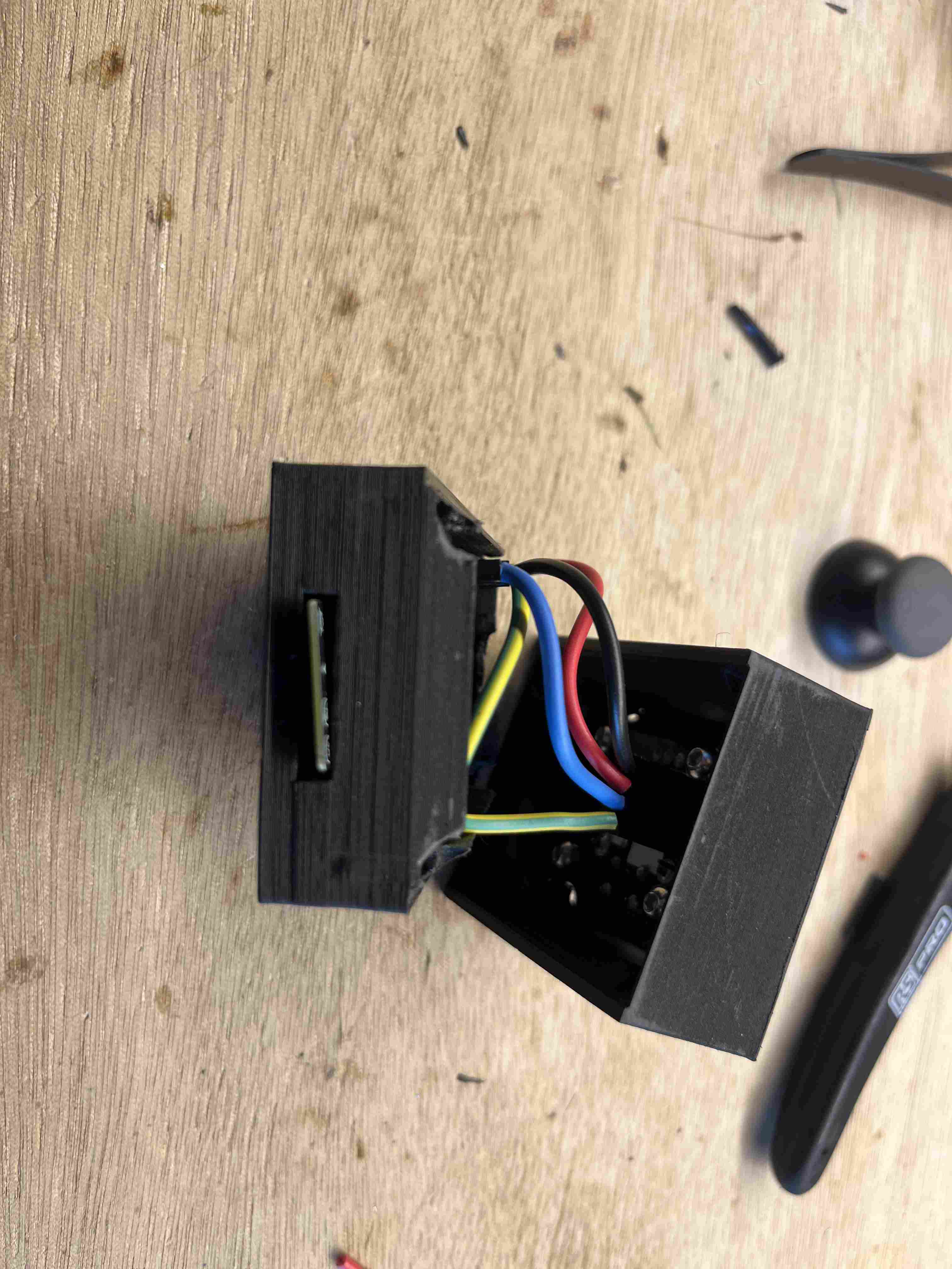
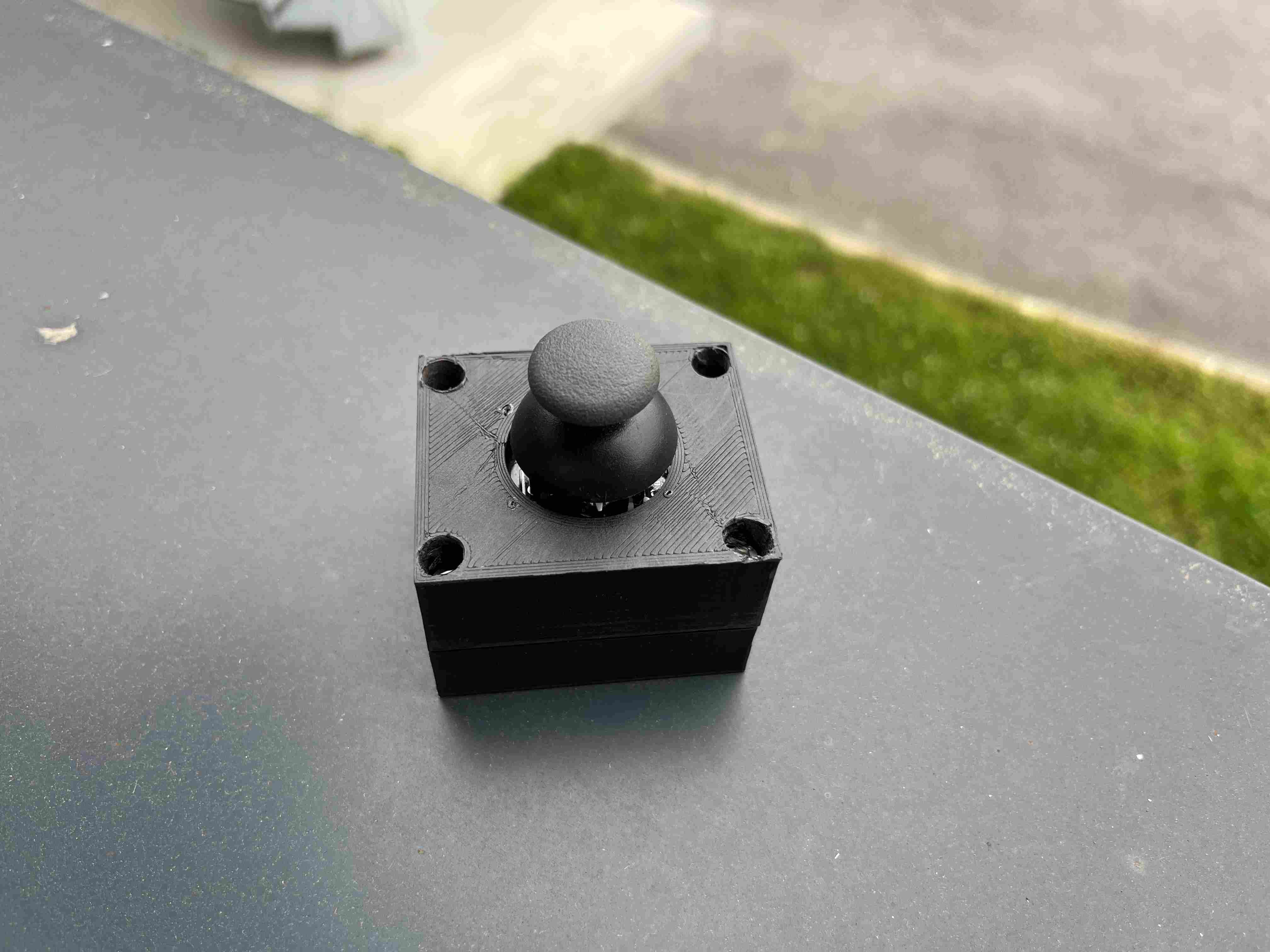
Stand
In order to hold the robot back so that it is not the robot frame that turns around the wheels, I had to find a solution. The first would have been to lower the robot's center of gravity by putting as much weight as possible on its lower part, so that the gravity would be greater than the force exerted by the wheels. This solution was risky, however, as the torque required to move the wheels forward was high, and there was a good chance that it wouldn't be effective. Another solution would have been to place a gyroscope high up on the robot. Using an IMU, we could then determine whether the robot was level and adapt its level by activating the gyroscope. This solution could probably be very effective, but would have required additional power consumption and time to set up. In order to carry out the tests, I therefore chose to use a final solution, putting a bar on the back to hold it in place. This isn't necessarily the best solution, but it proved effective.
BOOM
PCB
| Components | Quantity | Price | Remark |
|---|---|---|---|
| Micro-controller ESP32-WROOM-32UE | 1 | 2.50$ | |
| Button | 2 | 0,32$ each | |
| Regulator 3.3V 1A | 1 | 0.51$ | |
| vertical connector SMD 1x06 2.54mm | 1 | 0,93$ | |
| vertical connector SMD 1x04 2.54mm | 4 | 0,76$ each | |
| vertical connector SMD 1x02 2.54mm | 2 | 0,49$ each | |
| Resistor 10k Ohm | 5 | 0,10$ | |
| Resistor 500 Ohm | 1 | 0,10$ | |
| Resistor 0 Ohm | 7 | 0,10$ | |
| Led Green clear | 1 | 0,24$ | |
| Capacitor 10 µF | 1 | 0,6$ | |
| Capacitor 1 µF | 2 | 0,12$ | |
| Switch slide | 1 | 1,39$ | |
| Power connector jack | 1 | 1,80$ | |
| MOSFET N-CH 50V 16A TO252AA | 1 | 1,25$ | |
| Total | 15,42$ |
Electronic
| Components | Quantity | Prix | Remark |
|---|---|---|---|
| Batterie Lithium 12000mAh 6s 15C 22.2V | 1 | 180$ | Recovery from an old drone |
| Drivers MD13S CYTRON 13AMP DC MOTOR | 2 | 16.70$ each | |
| Cable USB | 1 | 4,13$ | |
| Wago 221, 3-pole | 1 | 1,10$ | |
| Emergency stop button | 1 | 16,30$ | |
| PLA | 45g | 1,86$ | |
| Cable | 1,5m | 9$ | |
| TOTAL | 229,09$ |
Mechanical part
| Components | Quantity | Price | Remark |
|---|---|---|---|
| Polycarbonate | 0,044m2 | 2,7$ | |
| MDF | 0,4m2 | 1.8$ | |
| Steel 3mm | 0,095m2 | 4,902$ | |
| Steel 5mm | 0,007m2 | 0,7$ | |
| hexagon socket head cap screw, M5 x 8mm | 66 | 13,22$ | |
| Hexagon socket screw, M5 x 10mm | 24 | 4,11$ | |
| Hammer nut M5 | 68 | 6,16$ | |
| Angle bracket for profiles | 24 | 16,68$ | |
| Aluminum profiles 20X20mm | 4,014m | 67,87$ | |
| Hexagonal head screws Stainless steel, M5 x 30mm | 28 | 12,83$ | |
| Brake nut M5 | 32 | 3,21$ | |
| Industrial swivel castor | 1 | 12,02$ | |
| Cylindrical head self-drilling screw | 8 | 1,51$ | |
| Allen screw, M6 x 20mm | 6 | 3,40$ | |
| Brake nut M6 | 1,65$ | ||
| Countersunk wood screws , 3mm x L 25mm | 31 | 1,56$ | |
| Threaded spindle Steel, M5 x 1m | 15cm | 0,65$ | |
| Motor MY6812 - 12 V - 120 W | 2 | 57,56$ | |
| Axis 10mm x L270mm | 2 | From recuperation | |
| Rangular contact ball bearing, ø int. 10mm, ø ext. 30mm | 4 | From recuperation | |
| Stop ring 10mm | 6 | From recuperation | |
| 53-tooth bicycle sprocket | 2 | 8,65$ both | From a local association |
| 11-tooth bicycle drive sprocket | 2 | 5,40$ both | From a local association |
| Bike chain | 2 | 8,65$ both | From a local association |
| Bike chain quick-release | 2 | 3,24$ both | From a local association |
| Ressorts | 2 | 3,24$ both | From a local association |
| Total | 180,712$ |
The first tests
The first tests turned out to be a failure. The risk I feared most turned out to be right: my motors didn't have enough torque to move my robot forward. Despite having sized them, we chose to buy smaller motors logically used to mount on electric bicycles, imagining that this would be sufficient, as these are logically capable of moving the weight of a human, and above all because they were less expensive. This decision was wrong and led to the robot's inability to move forward. In order to make it move anyway, we found the solution of using the laser cutter to cut a piece of MDF and then fixing it to the wheel bars to create a nice circle with a very small contact surface, which considerably reduced the torque required to move the robot.
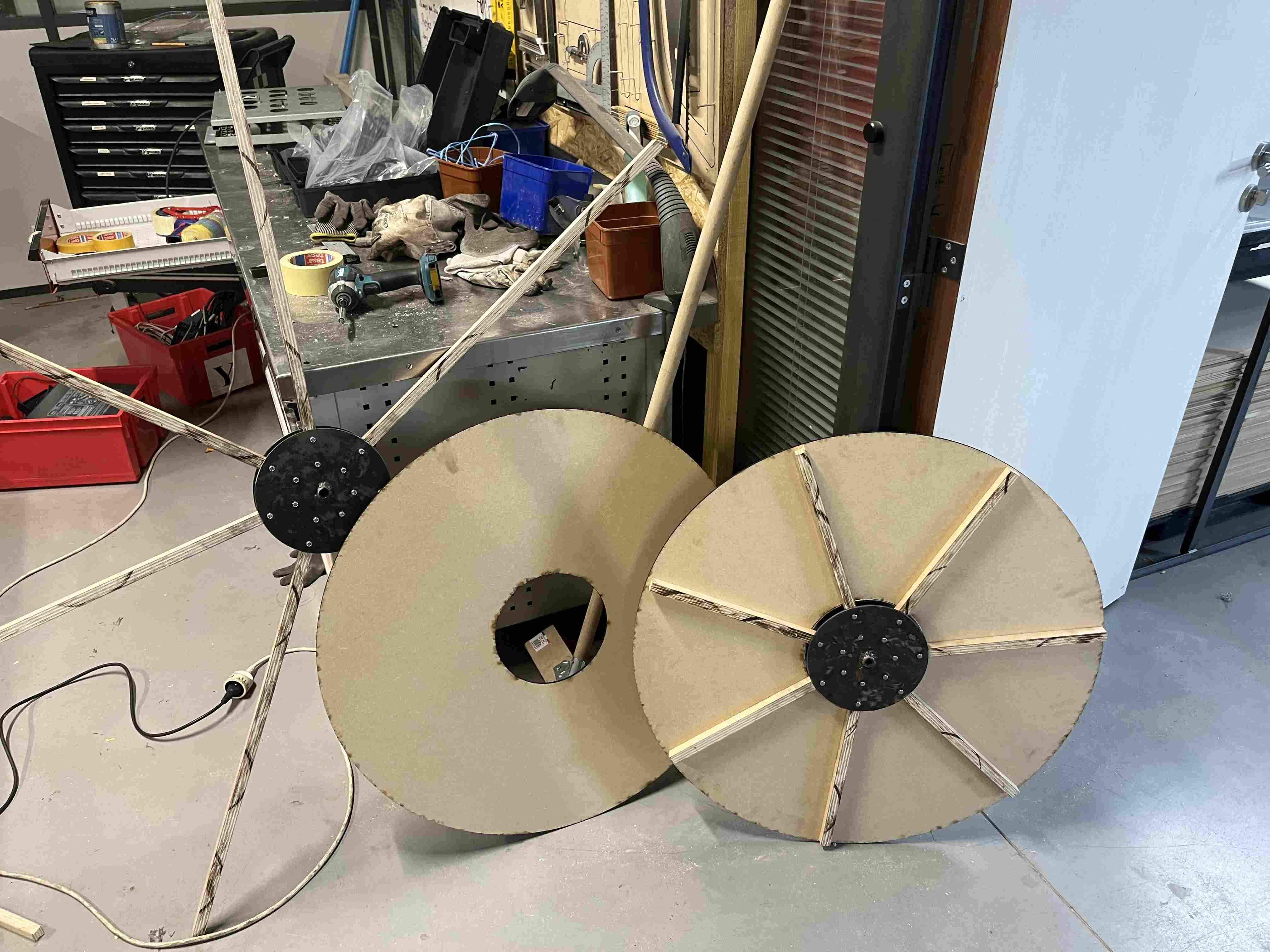
With this adaptation, the robot was able to launch itself and move forward on its own. However, it couldn't operate on fairly rigid surfaces, so it had to be on a smooth surface, like the agrilab floor for example, which is smooth concrete.
Once the wheels had been modified, the final version of the robot was as follows
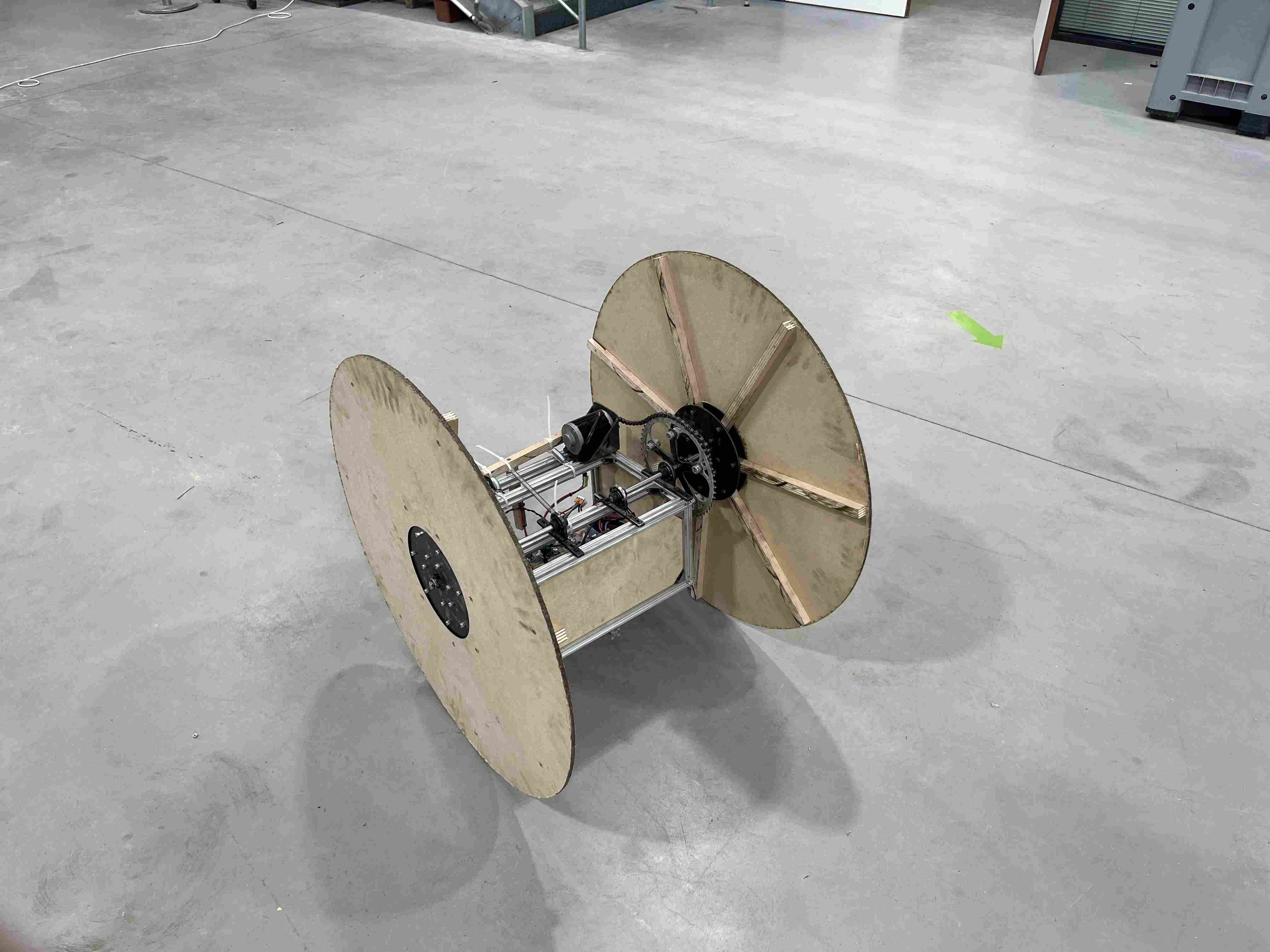
To get an overview of all these steps, you can find my presentation slide and video below.
