During this 6th week, we were particularly interested in programming and in particular the following assignments:
Group assignment:
Browse through the data sheet for your microcontroller
Compare the performance and development workflows for other architectures
Individual assignment:
write a program for a microcontroller development board that you made,
to interact (with local input &/or output devices)
and communicate (with remote wired or wireless devices)
extra credit: use different languages &/or development environments
extra credit: connect external components to the board
hero shoot
Group assignements
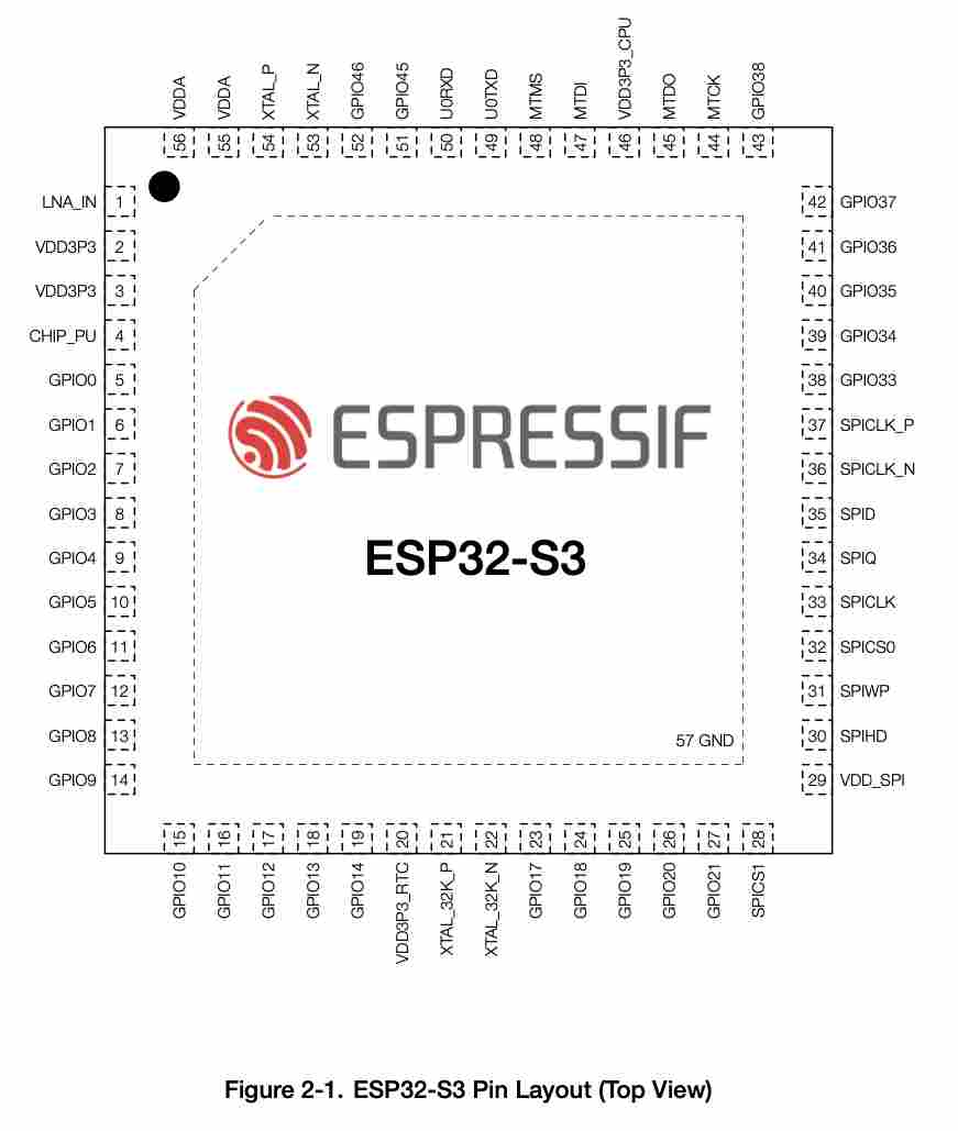
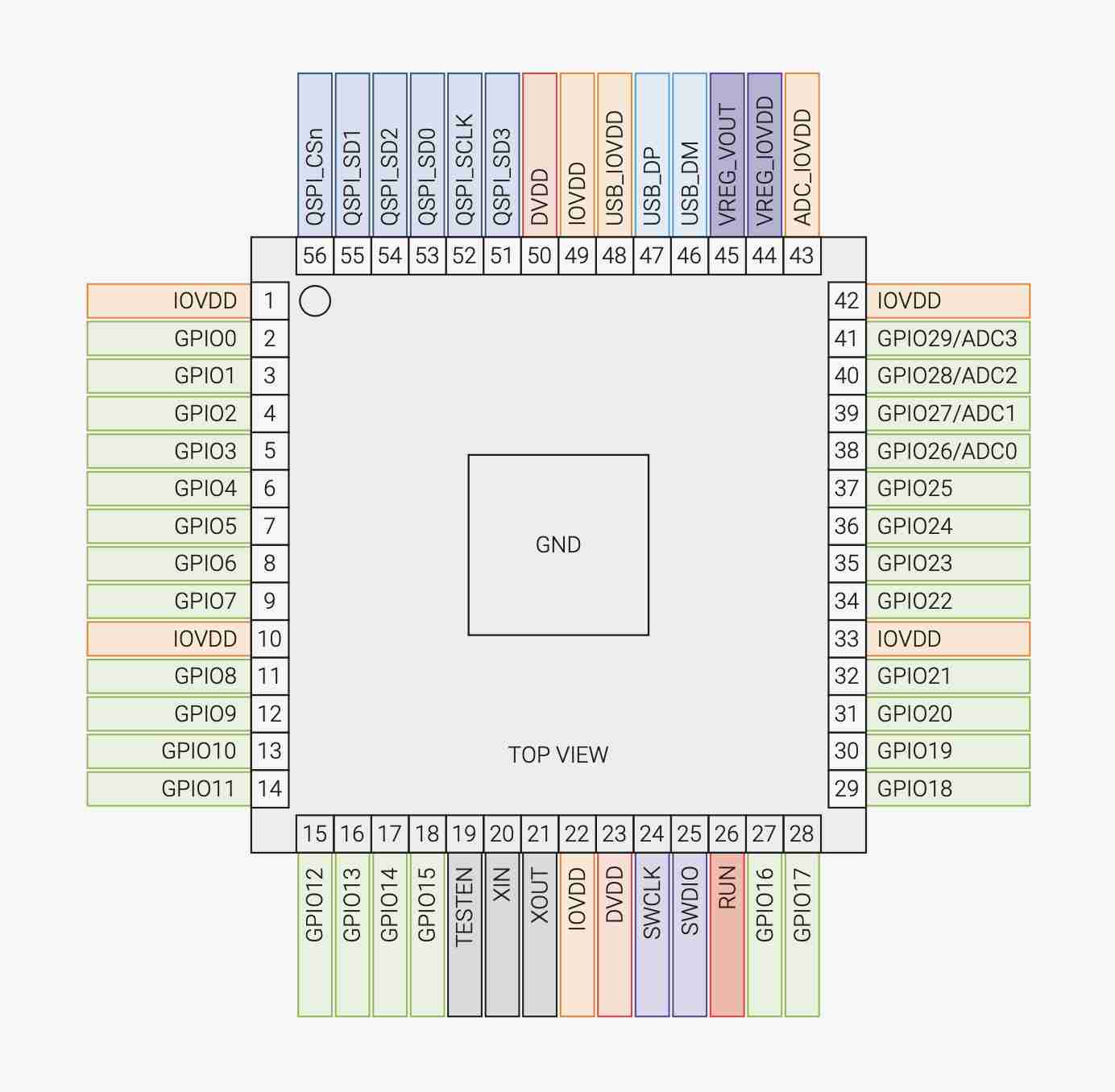
To make our group assignments, we looked at the datasheets of two different microcontrollers. The RP2040 was the obvious choice, as it was the one we used during the electronic production week, as well as this week with the Quentorres. The second one we've chosen to use is the ESP32 as we'll probably all be using it over the next few weeks and perhaps in our final projects. In order to provide the best possible documentation, we have put the various elements of the analysis in the form of a table.
| Feature | RP2040 | ESP32 - S3 |
|---|---|---|
| Processor | Dual-Core ARM Cortex MO+ | Dual-core Xtensa 32 LX7 bit |
| Clock speed | 133 Mhz | 2.4 GHz |
| Memory | 264kb SRAM & 2MB Flash | 512Kb SRAM & 384 Kb ROM |
| GPIO pins | 30 | 30 |
| Serial Interface | Brown-out Detect/Reset, DMA, I2S, LCD, POR, PWM, WDT | ADC, I2C, I2S, SDIO, SPI, PWM, UART |
| Analog inputs | 4 | 20 |
| Connectivity | None | Bluetooth 4.2 & WiFi 802.11b/g/n |
| Cost | 70ct | 1.85$ |
| Size | 7x7 mmm | 5x5 mm |
Comparing these two different microcontrollers, we can see that they are quite different, in many ways the ESP32 is better in every way, it works faster, it has more memory, more pins, it has wifi and bluetooth unlike the RP2040 which doesn't, and it's even smaller. On the other hand, it's twice as expensive. For simple projects like the ones we're doing, the RP2040 is more suitable, but if you need a more powerful microcontroller or Bluetooth and Wi-Fi functionality, you're better off using an ESP32..
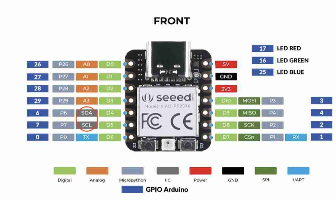
Vous pourrez également retrouver leurs shéma du PIn layout ci dessous
You can find all of our group assignments on the Agrilab page of the week
Individual assignements
In order to validate my custom assignments, I was first interested in making basic programs of the same type as blink.
Play with the button
I started by making a program where when I press the button, the 3 LEDs on the board go out and then come back on when I release the button. To do this I used the Arduino IDE that I'd used before. To help me write the code, I also used ChatGPT, which has served me well in discovering new functions.
First of all, the setup function is executed at the start of the code in order to declare the various outputs of the RP2040, in particular the button which is an input and the 3 LEDs which are outputs. Next comes the loop function, which will run continuously to perform the actions required for my code. You can find the detailed code below with explanations of the use of each function.
	const int button = 27;//declaration of the "button" constant
	 void setup() {
	  // initialize digital pin LED_BUILTIN as an output.
		pinMode(button, INPUT);
		pinMode(26, OUTPUT);//Led
		pinMode(0, OUTPUT);//Led
		pinMode(1, OUTPUT);//Led
		pinMode(LED_BUILTIN, OUTPUT);
		}
		// the loop function runs over and over again forever
		void loop() {
			int statebutton = digitalRead(button);//read whether the knob is in the open or closed position

			if (statebutton == LOW) {//is used to set a conditio
			digitalWrite(26, HIGH);  // turn the LED on (HIGH is the voltage level)
			digitalWrite(0, HIGH);  // turn the LED on (HIGH is the voltage level)
			digitalWrite(1, HIGH);  // turn the LED on (HIGH is the voltage level)
			delay(100);//action execution time (in milliseconds)

			} else{//is used to set a condition
			digitalWrite(26, LOW);   // turn the LED off by making the voltage LOW
			digitalWrite(0, LOW);   // turn the LED off by making the voltage LOW
			digitalWrite(1, LOW);   // turn the LED off by making the voltage LOW
			Serial.println(statebutton);//displays in the Arduino monitor whether the button is in the open or closed position
			delay(100);//action execution time (in milliseconds)
			}
		}
Compiling and uploading is the same process as for the week 4,select the card to which you want to send the code and press the button with the arrow to send it. Here's how the code works on the Quentorres:
I then created a small variation by making an extra LED light up each time I press the button, then when all three are lit, they reset to zero. To do this, I've kept the same code as before, adding the switch function which allows you to have different situations, and I've also created variables to store data so that the card knows where it is in terms of how many LEDs it has lit up.
// the setup function runs once when you press reset or power the board
 const int button = 27;//27
 const int led1 = 26;
 const int led2 = 0;
 const int led3 = 1;

 int buttonstock = HIGH;
 int statebutton = HIGH;
 int ledon = 0;
 void setup() {
  // initialize digital pin LED_BUILTIN as an output.
  pinMode(button, INPUT);
  pinMode(26, OUTPUT);//Led
  pinMode(0, OUTPUT);//Led
  pinMode(1, OUTPUT);//Led

  //pinMode(LED_BUILTIN, OUTPUT);
}

// the loop function runs over and over again forever
 void loop() {
  //define the numner of ledd on
  int statebutton = digitalRead(button);
  if (statebutton == LOW && buttonstock == HIGH) {
    ledon++;
    if (ledon > 3) {
      ledon = 0;
    }
  }
//switch on or off depending of the situation
  switch (ledon) {
    case 0:
      digitalWrite(led1, LOW);
      digitalWrite(led2, LOW);
      digitalWrite(led3, LOW);
      break;
    case 1:
      digitalWrite(led1, HIGH);
      break;
    case 2:
      digitalWrite(led2, HIGH);
      break;
    case 3:
      digitalWrite(led3, HIGH);
      break;
  }
  buttonstock = statebutton;
}
Here's a video of the result
Joystick and sevromotor
I wanted to try out different sensors, so I took a joystick and tried to read its information. In the case of my joystick, I had a fairly wide amplitude with a minimum of 5 and a maximum of 1023. Initially I was able to read the values on the Arduino IDE serial monitor and then I was able to read the values. I then wanted to use this joystick and these values to control a small servomotor. To do this, simply include the my servo library, which is normally already present on the IDE. We can then use the values read by the joystick to map them back to the servomotor. You can find the complete code below.
#include "Servo.h"//add the servomotor library
const int pinY = A3;
const int pinX = A2;
const int led1 = 26;
const int led2 = 0;
const int servo =2;
Servo myServo;

void setup() {

  Serial.begin(9600);
  pinMode(26, OUTPUT);//Led
  pinMode(0, OUTPUT);//Led
  pinMode(1, OUTPUT);//Led
  myServo.attach(servo);


}

void loop() {
  //read the joystick values
  int xvalue=analogRead(pinX);
  int yvalue=analogRead(pinY);
  Serial.print("X: ");
  Serial.print(xvalue);
  Serial.print("\t Y: ");
  Serial.println(yvalue);
  delay(100); // Délai pour éviter les lectures trop fréquentes
int servoAngleX = map(xvalue, 5, 1023, -180, 180);//mapping for have a good relation between the servo and the joystick

//switch on the led if x>900
if (xvalue>900){
  digitalWrite(led1, HIGH);

}else{
  digitalWrite(led1, LOW);
}
if (yvalue>900){
  digitalWrite(led2, HIGH);
}else{
  digitalWrite(led2, LOW);
}
//move the servo with the x value
myServo.write(servoAngleX);
}
LCD screen
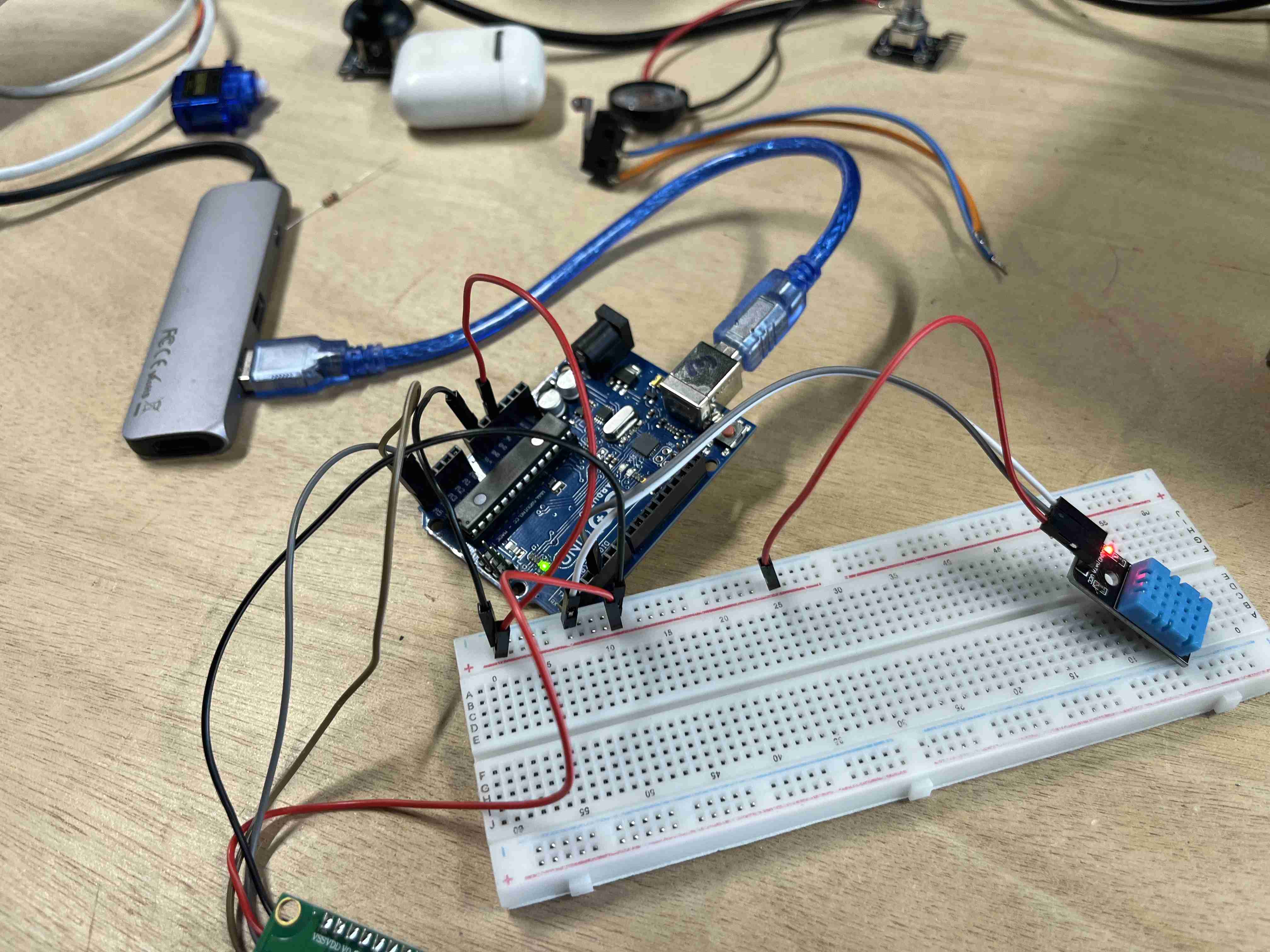
I then wanted to use an LCD screen because I think it can be very useful for programming anything, so I first looked at adocumentation about the wiring, so that it can be connected properly. By default, this type of screen is connected to analogue pins 4 and 5. Unfortunately, on our RP2040, we only go up to three, or at least I thought it was impossible. So I left my Quentorres behind and got an Arduino Uno to make the task easier. I then had to download the LiquidCrystal_I2C.h library to be able to control the LCD screen, the commands we're going to use are fairly simple, once we've defined the screen we want to tile, all we have to do is initialise it, switch on the backlight, and finally ask to display what we want on the desired screen. To get started I did a simple hello world, to see if it worked.
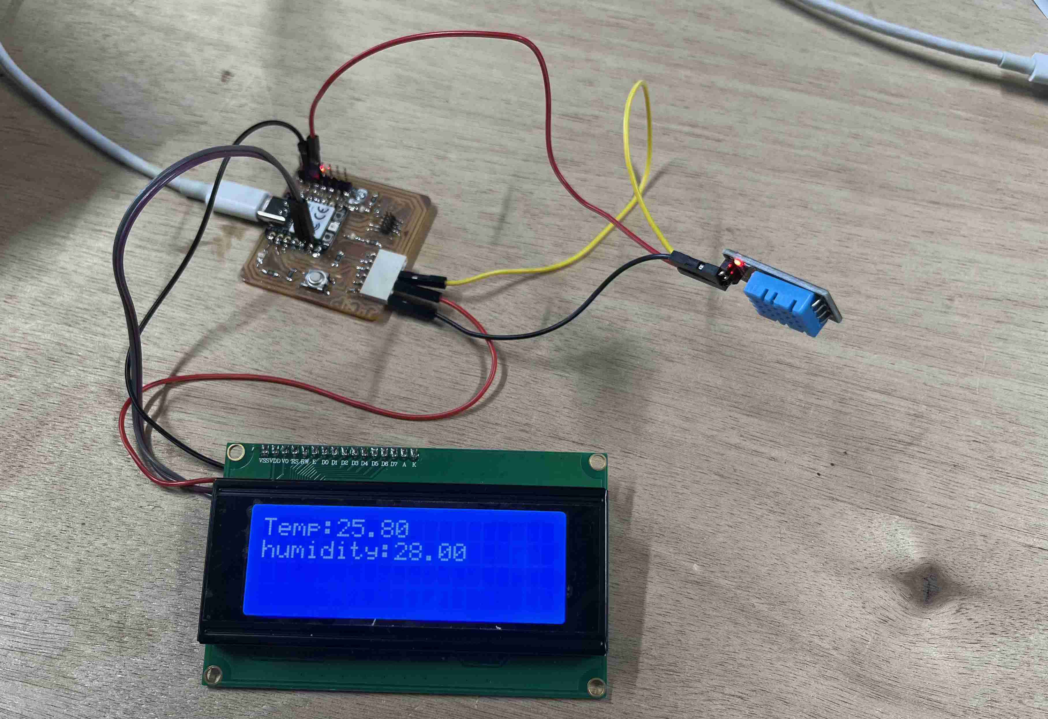
Once I'd got to grips with the screen, I found a DHT11 humidity and temperature sensor, which integrates both data. In order to use it, I downloaded theDHT Sensor Library, from Adrafruit, which makes it even easier to use these sensors. It's the same principle as for conventional sensors: we declare them, then read the data and finally display them on the screen. You can find the final code below, I haven't just put the one with the screen because the one with the sensor also includes all the data.
#include "LiquidCrystal_I2C.h"//includes the liquidcrystal library
#include "DHT.h"//Includes the DHT library
LiquidCrystal_I2C LCD(0x27, 20, 4); // defines the type of 16 x 2 lcd screen
#define DHTPIN 28//defines the pin used
#define DHTTYPE 11//defines the type of DHT
DHT dht(DHTPIN, DHTTYPE);

void setup() {
  Serial.begin(9600);
  LCD.init(); // display initialisation
  dht.begin();//start reading
}

void loop() {
  float temp = dht.readTemperature();//assigns the temp variable to the DHT11 value
  float humidity = dht.readHumidity();//assigns the humidity variable to the DHT11 value
   if (isnan(temp) || isnan(humidity)) {//sends a message if it cannot read the values
    Serial.println("Error reading DHT11 sensor !");
    return;
  }
   //. LCD screen management
 LCD.backlight();//turns on the screen backlighting
//sends values to the serial monitor
  Serial.print("température:");
  Serial.println(temp);
  Serial.print("Humidité:");
  Serial.println(humidity);
  Serial.print("%");
//Displays the values on the screen
 LCD.setCursor(0, 0);//choice of line
 LCD.print("Temp:");
 LCD.print(temp);
 LCD.setCursor(0,1);
 LCD.print("humidity:");
 LCD.print(humidity);
delay(1000);
}
Here's what the circuit looks like when assembled and in operation. You can see that it's working well: when I place my hand on the sensor, the temperature and humidity increase significantly.
I had problems using the LCD screen, even though I'd coded everything correctly and plugged it into my Arduino, the screen had power because I could see the backlight come on but nothing was displayed. I found a library on the internet called I2CScanner and which can be used to determine which type of I2C device is connected to our board. To scan it, simply download the library and follow the path below:

Once the sketch is open, simply upload the programme to the card and open the serial monitor. This will display the results of the analysis. In my case, I realised that my screen had a problem because I had the following message:
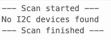
I found the same screen in stock and tried it, it worked straight away so my LCD screen was broken.
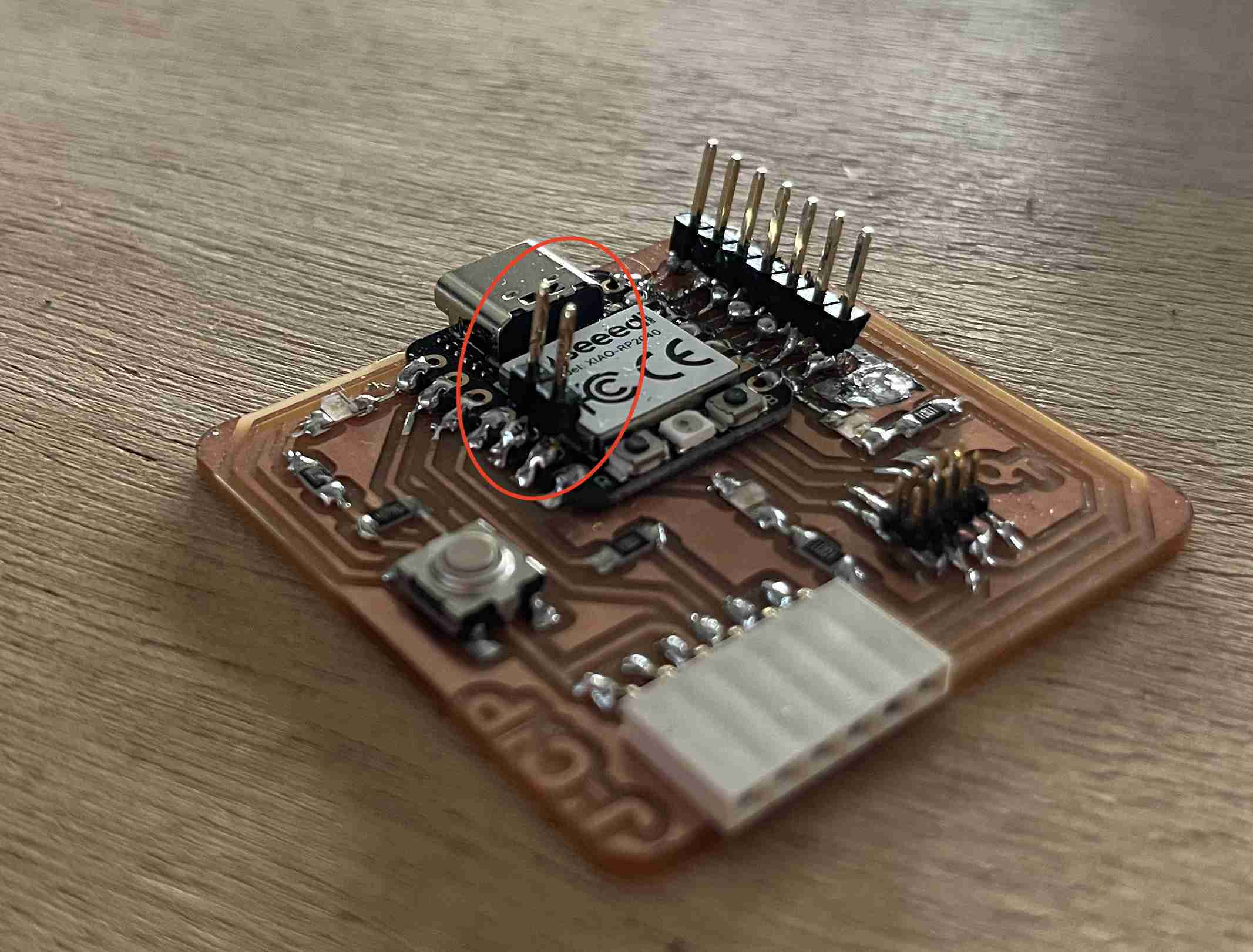
Concerning my change of board to an Arduino, this choice wasn't necessarily necessary, my instructor assured me that it's perfectly possible to connect an LCD screen. So I went back to look at the board's documentation and realised that two pins were dedicated to the SDA (Serial Data Line) and SCL (Serial Clock Line) respectively. I tried again on my RP2040, but these two pins weren't connected to anything according to the board assembly, so I soldered on these pins and fitted a connector, allowing me to connect my LCD screen.
I redid my connections, and put the programme on the card and it was effortless to get a result.
Codes used
-Button and led 1
-Button and led 1
-Joystick and servo
-Test sensor DHT11