Welcome to my machine week page. If you would like to see the entire creation of the machine, please refer to our documentation on our Agrilab group page.
During this tenth week, we're looking at mechanical design and machine design. Our assignments were as follows for the mechanical design part:
Group assignments:
- design a machine that includes mechanism+actuation+automation+application
- build the mechanical parts and operate it manually
- document the group project and your individual contribution
For the machine design part, the assignments were as follows:
Group assignments:
- actuate and automate your machine
- document the group project and your individual contribution
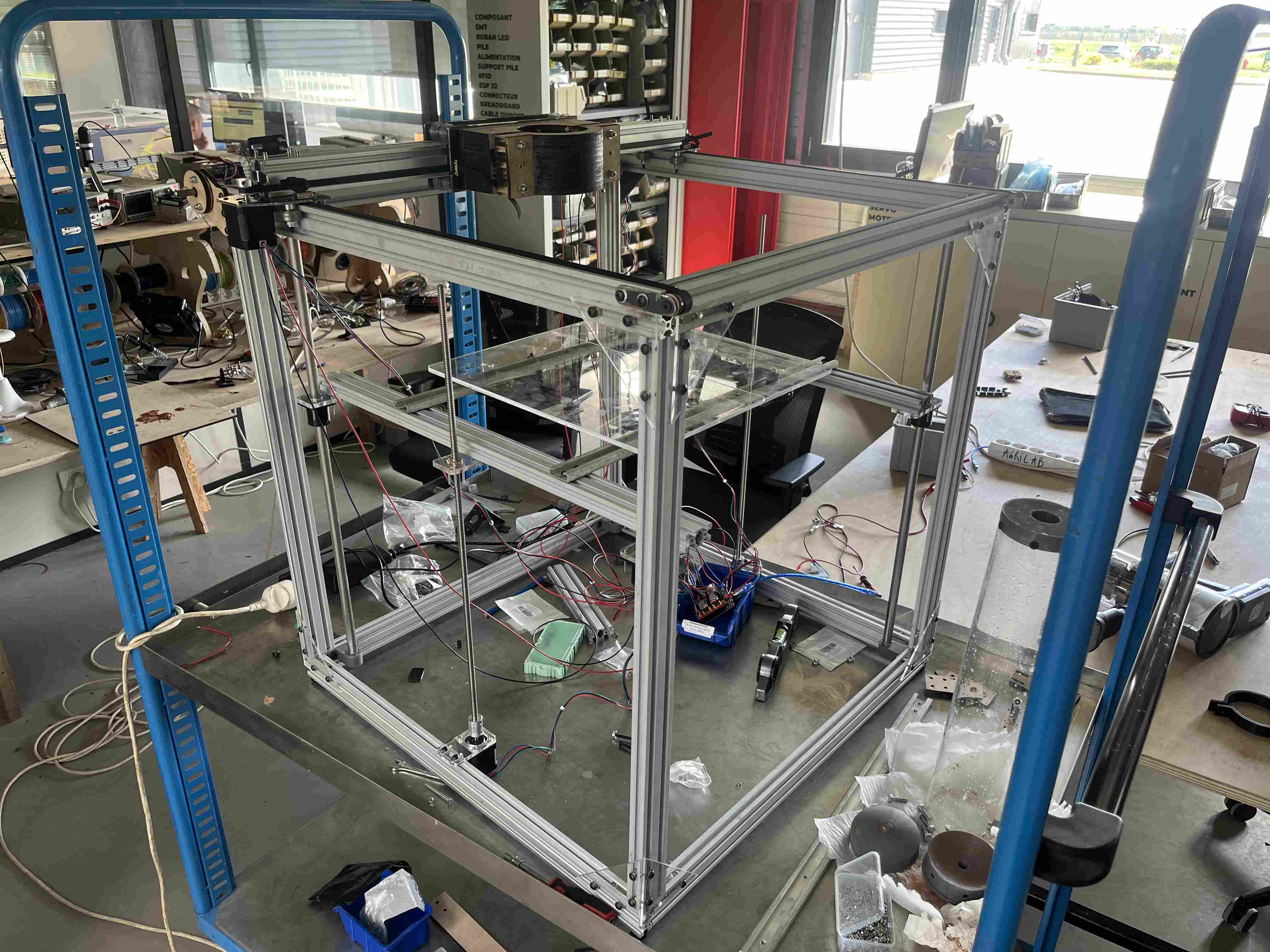
So this week was mainly about group work. We had to agree on the machine we wanted to make together. After thinking about the different types of machine we could make, we decided to make a ceramic 3d printer. It's a classic 3d printer with a few differences. We're printing clay, not plastic, so the platen doesn't need to be heated, and neither does the extruder. On the other hand, the weight carried by the whole system is greater than on a conventional 3D printer.
In order to divide up the tasks and work efficiently, while following each other's work and exchanging our opinions, we decided to each specialise in a specific area. It's important to point out that we chose to make a Cartesian-type printer with the platen rising from top to bottom for the Z axis, to avoid shaking our print. Alexis was in charge of making the platen and the Z axis, Pol-Emile was in charge of making the clay extrusion system and I was in charge of moving the X and Y axes at the top of the machine.
X and Y axis design
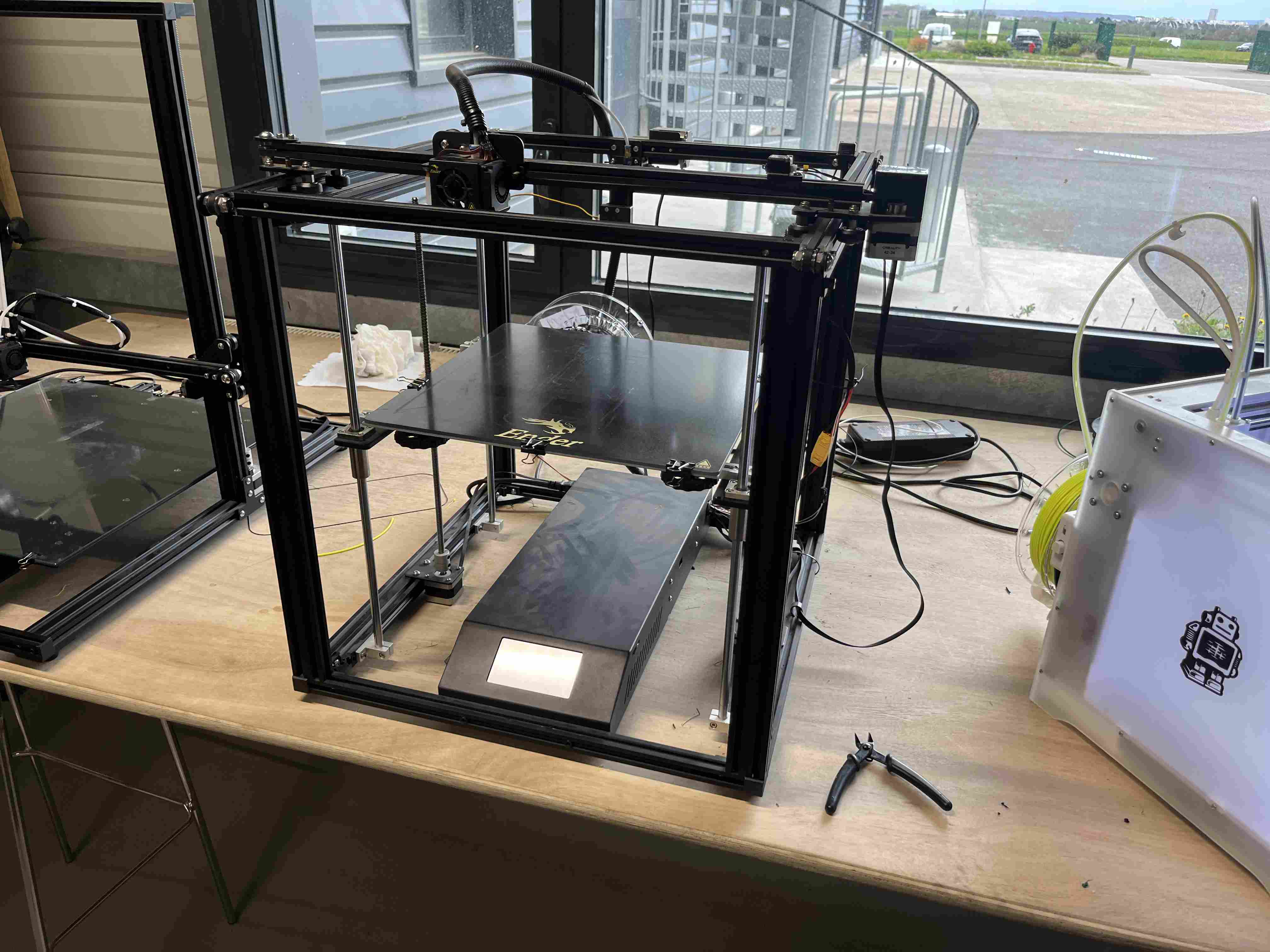
So as not to launch ourselves into the unknown, we decided to take our inspiration from the only printer with a rising platen at Agrilab, the Creality Ender 5 plus. You will therefore notice that a large proportion of our designs are directly inspired by its operation, with adaptations of course to better suit our material, which is clay.
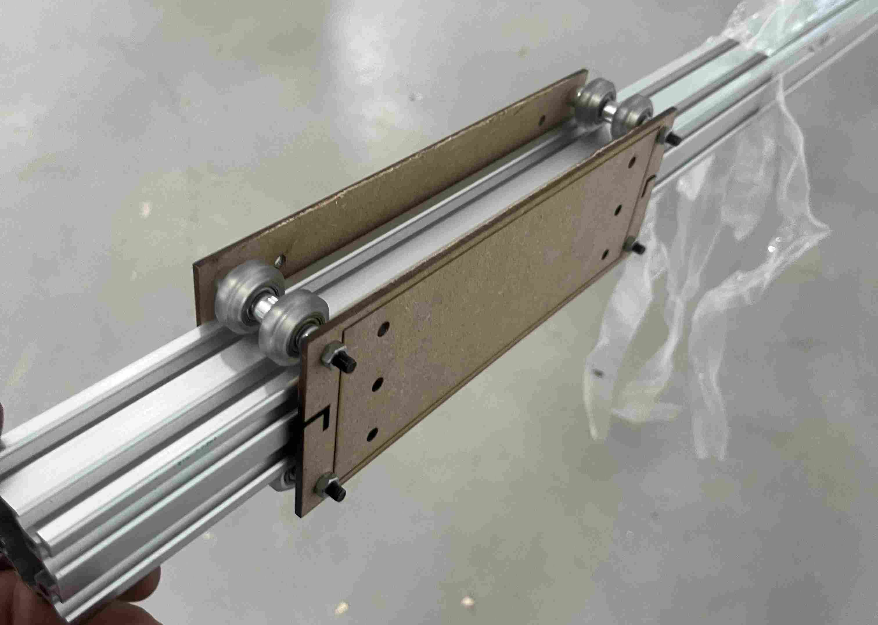
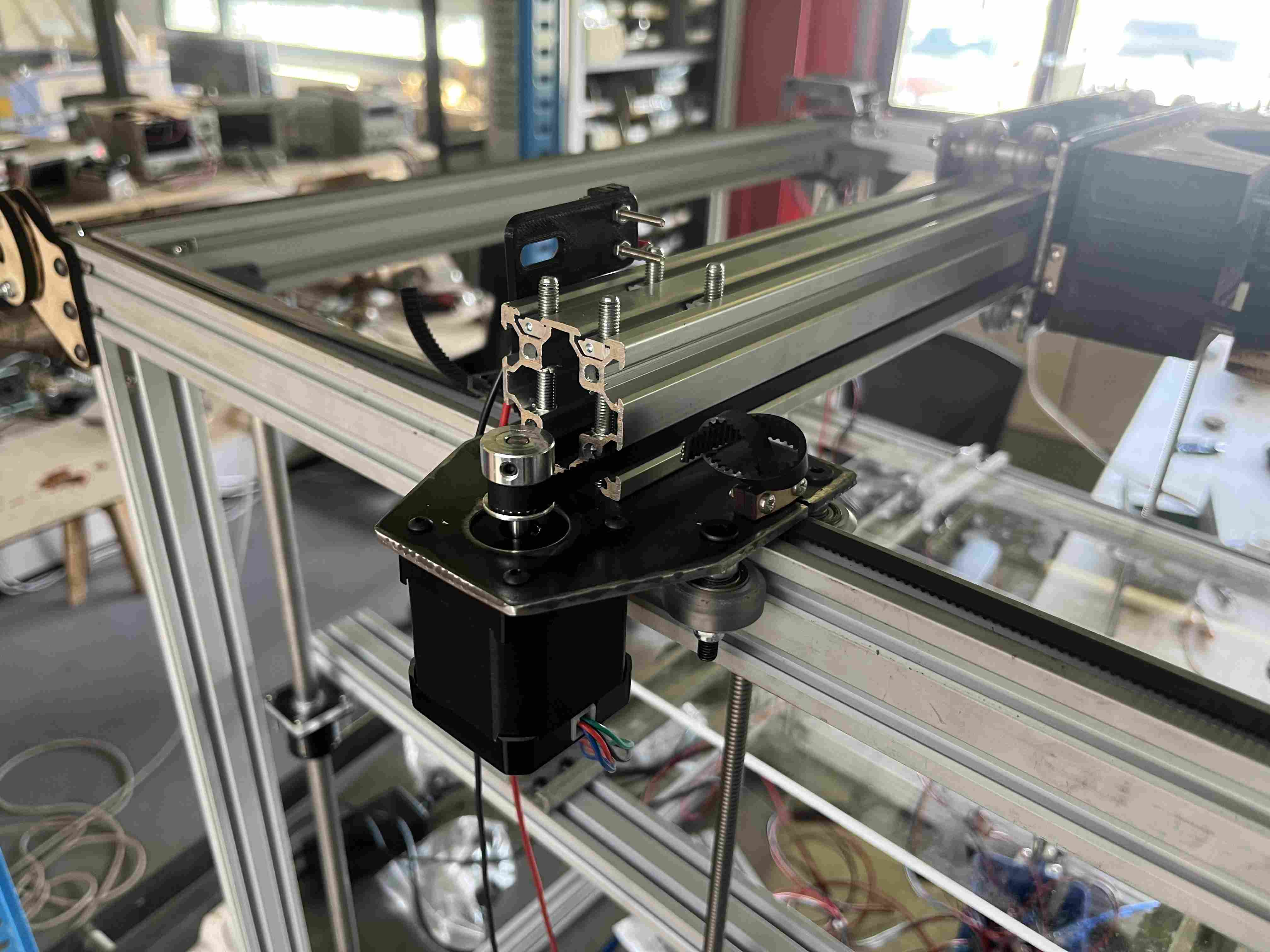
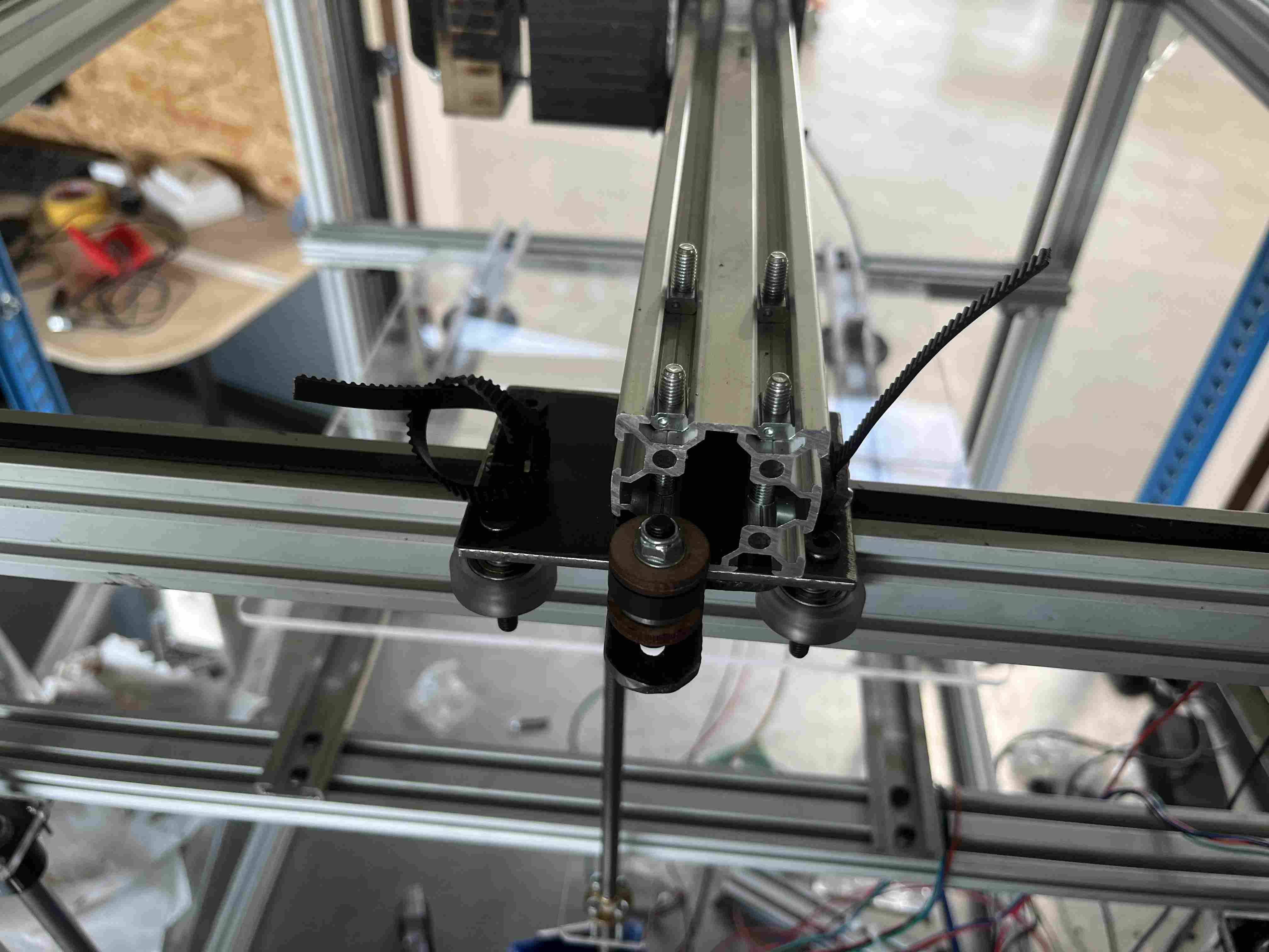
To get started, I created some designs on Fusion 360 In order to create my plates for the X and Y axis supports, I came up with different designs, taking into account the spacing of the castors so that they pass on either side of the profiles.
I've carried out this operation on various parts, including the carriage supporting the extruder and various motor and tensioner supports.
Once I'd modelled my turntables, I started by cutting them out of 3mm MDF. I chose this material because it's fairly solid and is the same thickness as the steel I used later. I had to make a few adaptations in order to solve problems that I hadn't considered at the design stage, and that's where the great advantage lies in carrying out initial tests in wood before moving on to steel, which is more expensive and takes longer to work on. I was right to carry out the initial tests in wood because to case each part, I had to make modifications, which saved me a lot of time.
Once I had a design that looked good in mdf, I was able to make the metal finishes. To do this, we used the plasma cutter during fabacademy's machine week in 2022.
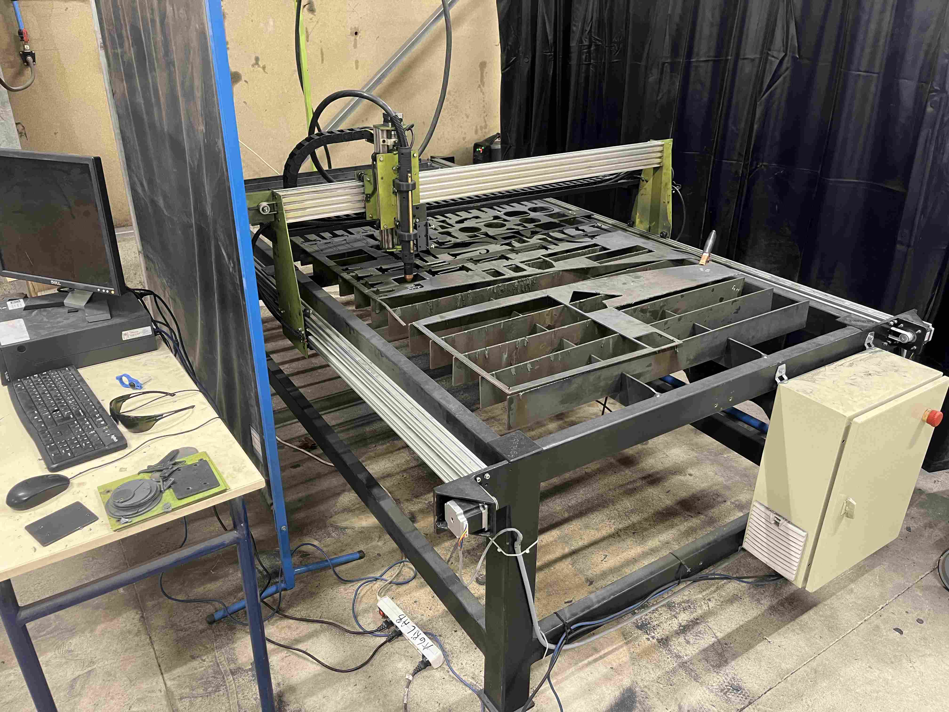
To prepare the file for plasma cutting, I reduced the size of all the holes to 1.8mm, because the machine is constantly being improved and can't yet cut as precisely and cleanly as with a drill.
To use the laser cutter, we have a computer running the Linux operating system. First, we prepare the dxf files with the Sheetcam which generates a gcode in . tap format that we can then open with the software Linux CNC which controls the cutting machine. Find out more about how to use our cutting machine here and here.
Once my parts were cut out, I took the drill press and drilled the various diameters I needed (3.5, 5, 7) as well as a step drill for the 22.5mm holes where the motors would fit.
Once I'd made all my holes, I was able to sand the edges and drill exits to get a smoother, less sharp result.
Once I'd made my pieces, I could move on to the assembly stage, for which I used various materials that you'll find in the list below.
| Composant | Number |
|---|---|
| wheels | 16 |
| screw M5 60mm | 8 |
| screw M5 50mm | 11 |
| screw M5 7mm | 12 |
| Precision washers 1mm | 24 |
| brake nuts m5 | 24 |
| hammer nuts | 20 |
| eccentric spacer m5 | 8 |
| 6mm spacer | 8 |
| 9mm spacer | 4 |
| 40mm spacer | 4 |
| Steel 3mm | |
| MDF 6mm | |
| MDF 2mm | |
| bearings 16mm | 6 |
| bearings 30mm | 1 |
| gt2 belts | 2 |
| 8mm steel axle | 1 |
| Stepper motor Nema 17 | 2 |
| gt2 8mm gear | 2 |
| gt2 5mm gear | 1 |
| 5mm threaded rod | 1 |
| washers | 16 |
| profile 40X40mm | 730mm |
| profile 20X40mm | 2,6m |
Once all these different elements were assembled, we were able to mount them together. In my case, my designs were only fixed using castors.
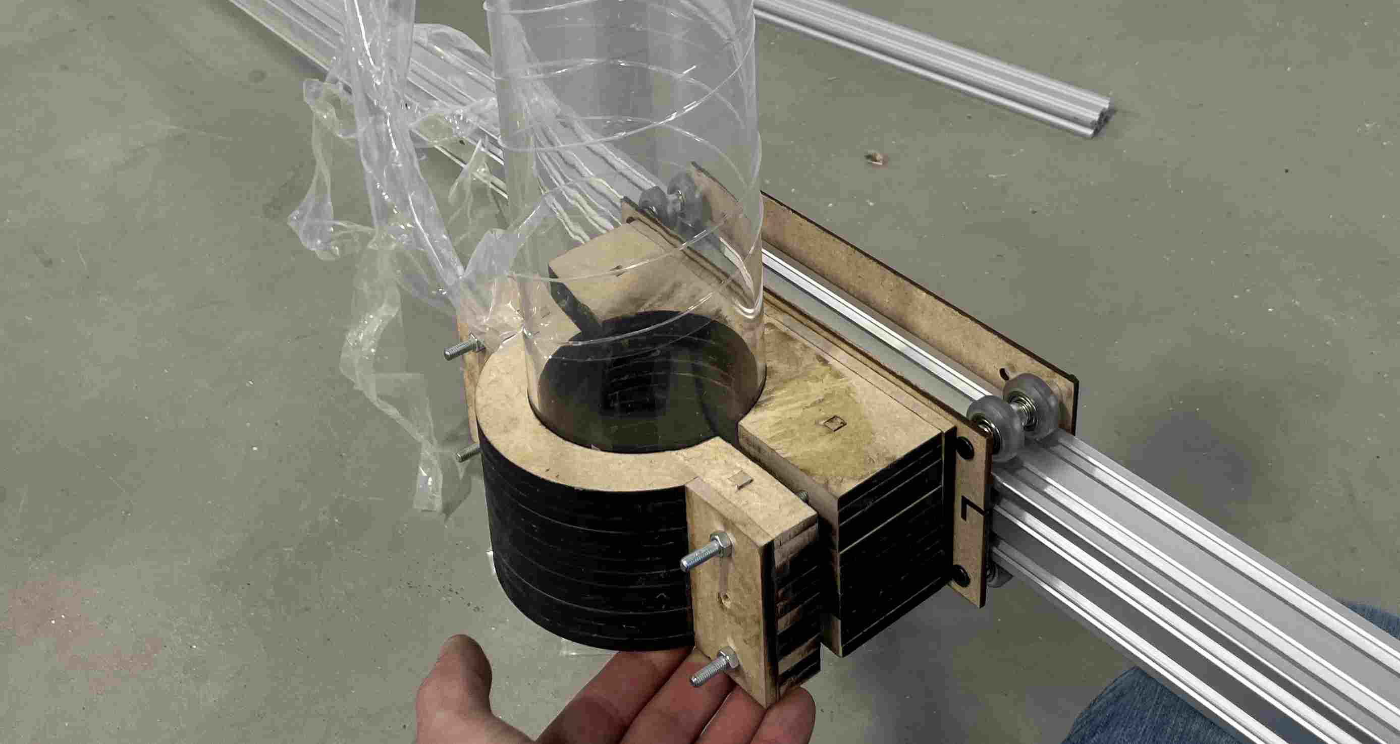
Tube support
To hold our clay tank, I made a support to hold our tube firmly on our X-axis carriage. As the tubes we have have a large diameter, we had to make a fairly long carriage that takes up a lot of space. The support is also very large. I produced a design on Fusion 360 to hold our tube on our support. As for the height of our concption, I based it on the height of the patina. As the part was very important, it required 20 hours of printing time, and as I didn't have the time, I decided to cut it into slices and cut it with the laser cutter in 6mm MDF, which saved me precious time. To prevent the layers coming unstuck during drilling and clamping, I replaced the last parts of the flat faces with a piece in the opposite direction.
If you would like to reproduce any of the pieces, you can do so by clicking on the following links
| Localisation | Components |
|---|---|
| Y axis | Single trolley |
| Y axis | Motor X trolley |
| Y axis | Support plate |
| Y axis | Motor plate |
| Y axis | Bearing support |
| Y axis | Bearing support |
| Y axis | Tensioner |
| X axis | Extruder trolley |
| X axis | tensionner |
| Belts | tensionner |
| Extrudeur | Tube support |
Electronics
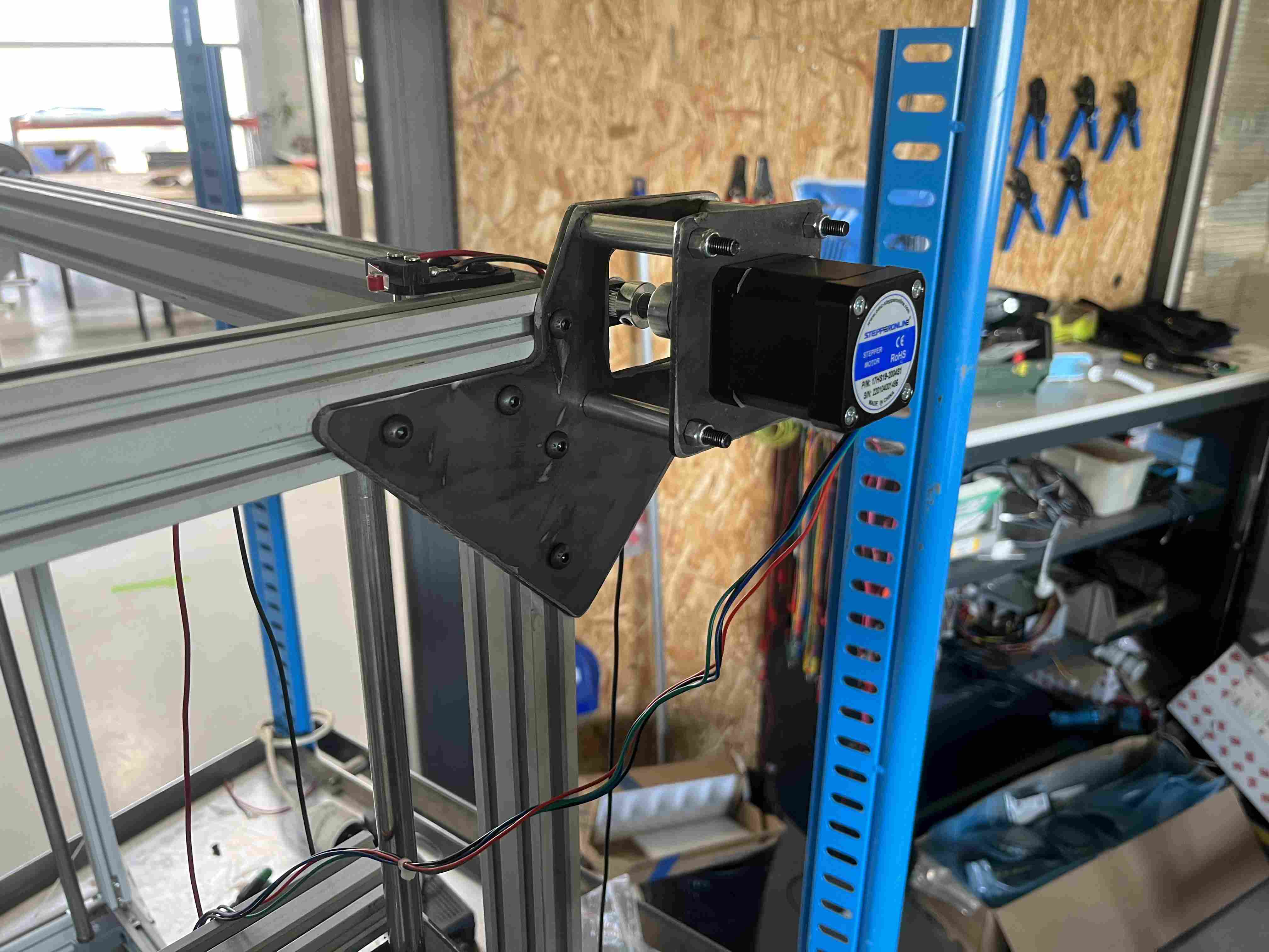
In order to control our printer, we have chosen to use nema 17 stepper motors from stepper online for controlling the X, Y and Z axes of our printer. For the extrusion part, we chose to use a larger motor in order to have enough force to push the clay.
In order to test all the engines by activating them, I used the code below which I found on this page We carried out the usual assembly except for the Z axis, where we added an extra driver to control the second Z axis motor. In order to control the drivers A4988, we're using a shield connected to an Arduino UNO.
The code I used to test the stepper motors is as follows:
const int enPin=8;
const int stepXPin = 2; //X.STEP
const int dirXPin = 5; // X.DIR
const int stepYPin = 3; //Y.STEP
const int dirYPin = 6; // Y.DIR
const int stepZPin = 4; //Z.STEP
const int dirZPin = 7; // Z.DIR
int stepPin=stepYPin;
int dirPin=dirYPin;
const int stepsPerRev=200;
int pulseWidthMicros = 100; 	// microseconds
int millisBtwnSteps = 1000;
void setup() {
 	Serial.begin(9600);
 	pinMode(enPin, OUTPUT);
 	digitalWrite(enPin, LOW);
 	pinMode(stepPin, OUTPUT);
 	pinMode(dirPin, OUTPUT);
 	Serial.println(F("CNC Shield Initialized"));
}
void loop() {
 	Serial.println(F("Running clockwise"));
 	digitalWrite(dirPin, HIGH); // Enables the motor to move in a particular direction
 	// Makes 200 pulses for making one full cycle rotation
 	for (int i = 0; i < stepsPerRev; i++) {
 			digitalWrite(stepPin, HIGH);
 			delayMicroseconds(pulseWidthMicros);
 			digitalWrite(stepPin, LOW);
 			delayMicroseconds(millisBtwnSteps);
 	}
 	delay(1000); // One second delay
 	Serial.println(F("Running counter-clockwise"));
 	digitalWrite(dirPin, LOW); //Changes the rotations direction
 	// Makes 400 pulses for making two full cycle rotation
 	for (int i = 0; i < 2*stepsPerRev; i++) {
 			digitalWrite(stepPin, HIGH);
 			delayMicroseconds(pulseWidthMicros);
 			digitalWrite(stepPin, LOW);
 			delayMicroseconds(millisBtwnSteps);
 	}
 	delay(1000);
}
Thanks to this code, I was able to control the operation of my motors and make them work.
Calculating VREF
Our motor drivers have a potentiometer for adjusting this. But you have to calculate it first. To do this, I've found the following formula:VREF = Maximum motor current(Amps) * 8 * Potentiometer resistance(Ohms)
| Parameter | Value |
|---|---|
| maximum curent | 2A |
| Resistor | 0,05 Ohms |
| VREF | 0.8V |
Using these values, not all the motors worked, some made noise and shook, so I adjusted the motors while they were running to determine the correct value. Once I had a working system I didn't change the values again.
GRBL
To make our printer work, we originally decided to use the Marlin which is very well known. However, we were running late and decided to use the printer with the GRBL much easier to use. Simply download the zip file, unzip it, open it and paste the folder grbl dans le dossier Arduino>libraries file on our computer. We can then go to the grbl > examples > grblUpload and open the .ino file with the Arduino IDE. You can then upload it to your Arduino UNO.
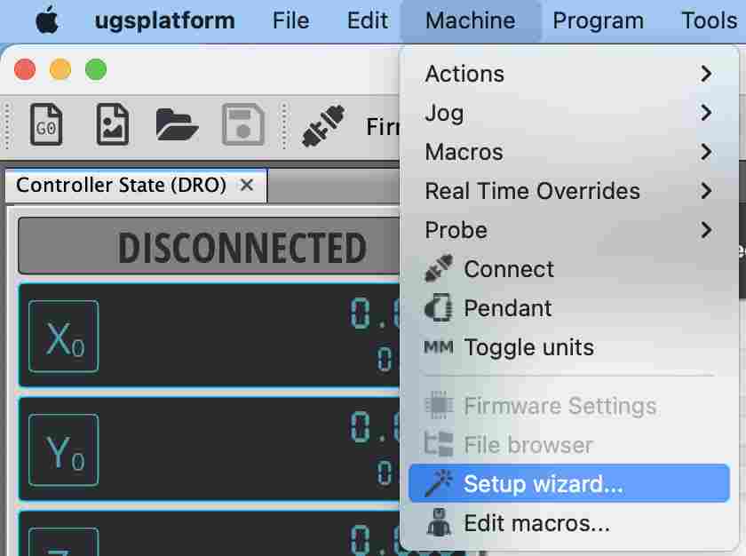
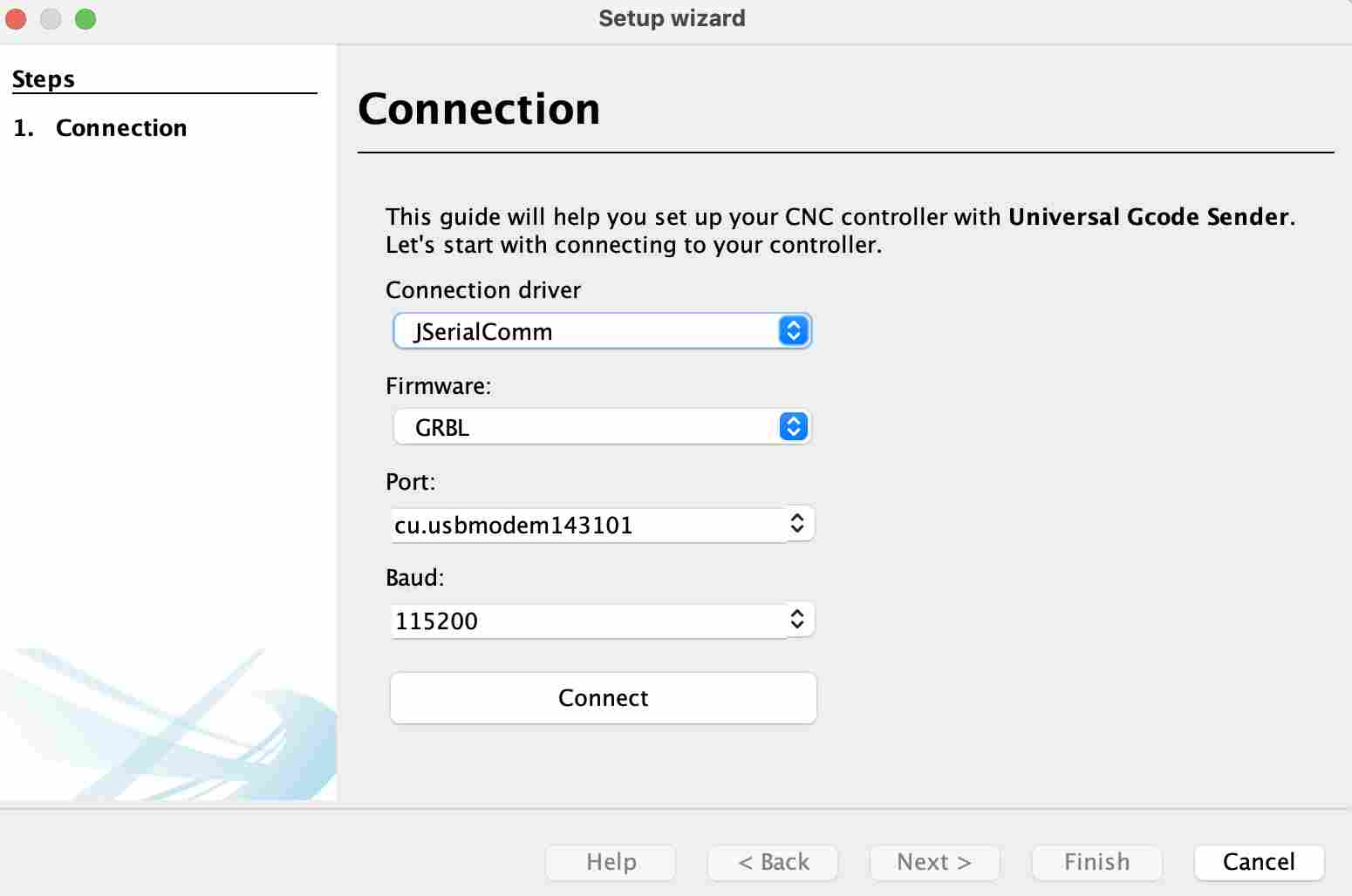
Once the arduino has been configured with grbl, you can download Universal GCode Sender which will allow us to control the printer. To use it, open it and go to tools then Setup wizard. A window will open where you can select different parameters and try to connect.
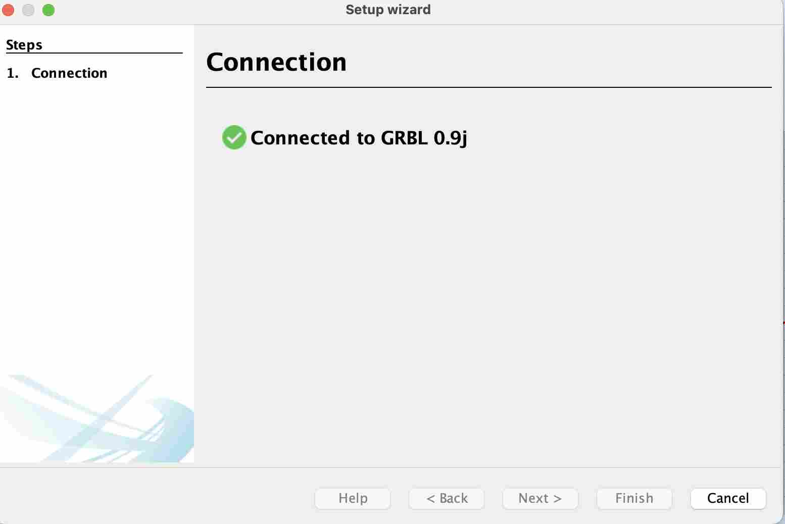
Once the contact has been made, we receive a message saying that it has been successfully connected and we can then start configuring the printer.
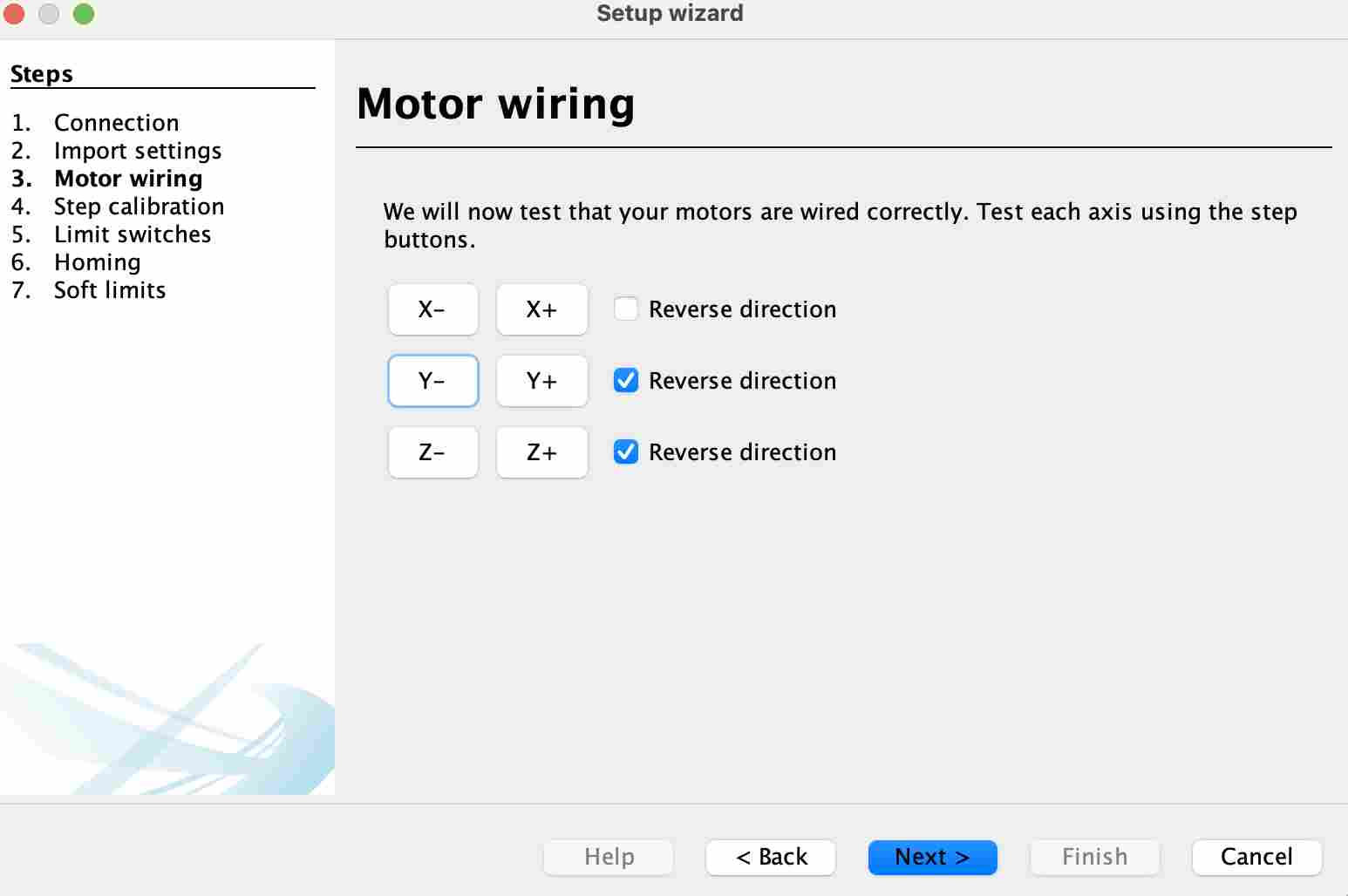
We can then check the engines by checking their direction and whether they move well or whether there are any electronic problems.
I then stopped for lack of time at the calibration stage, here are the values I had determined for our different axes:
| Axe | Number of motor steps per revolution | Number of thread/belt pitches per revolution | Value(step/mm) |
|---|---|---|---|
| X | 200 | 40 | 5 |
| Y | 200 | 40 | 5 |
| Z | 200 | 2 | 100 |
To arrive at these results, I used the following formula: Value(step/mm)=Number of motor steps per revolution/Number of thread or belt pitches per revolution