Week 10 - Mechanical design - Machine design
group assignment
- design a machine that includes mechanism+actuation+automation+application
- build the mechanical parts and operate it manually
- actuate and automate your machine
- document the group project and your individual contribution
Through our discussion, we decide to create a ceramic printer.
Hero shot
Planification (Group discussion)
First we read some documentation and watched videos about it. Anoush and Michelle shared us some links for inspiration :
- https://www.bryancera.com/cerastruder
- https://3dprinting.com/news/transform-your-3d-printer-into-a-versatile-paste-extrusion-add-on/
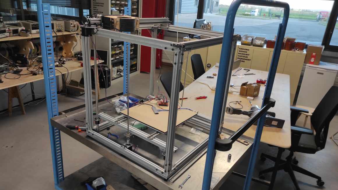
We first agreed on the general design of the machine, which is a Cartesian machine inspired by the Ender CR10S5 with a DirectDrive extrusion. Considering the presumed weight of the tank, a movable bed on the Z axis seemed more relevant to us to avoid overloading the motor. Then, we divided the tasks: Alexis took care of the bed and the overall structure of the machine, Jean-Come handled the motor programming and then worked on the X and Y axes, and Pol-émile worked on the extrusion system.
Alexis also contacted Adel Kheniche (maker, fabmanager and former Fabac student and instructor) he met last year in a FabLAb in Genneviliers, whose experimenting ceramic printing for about a year to share experiences whit it, advantages and inconvenients with the printer he uses…
Bed and overall structure (Alexis)
Bed first sketch
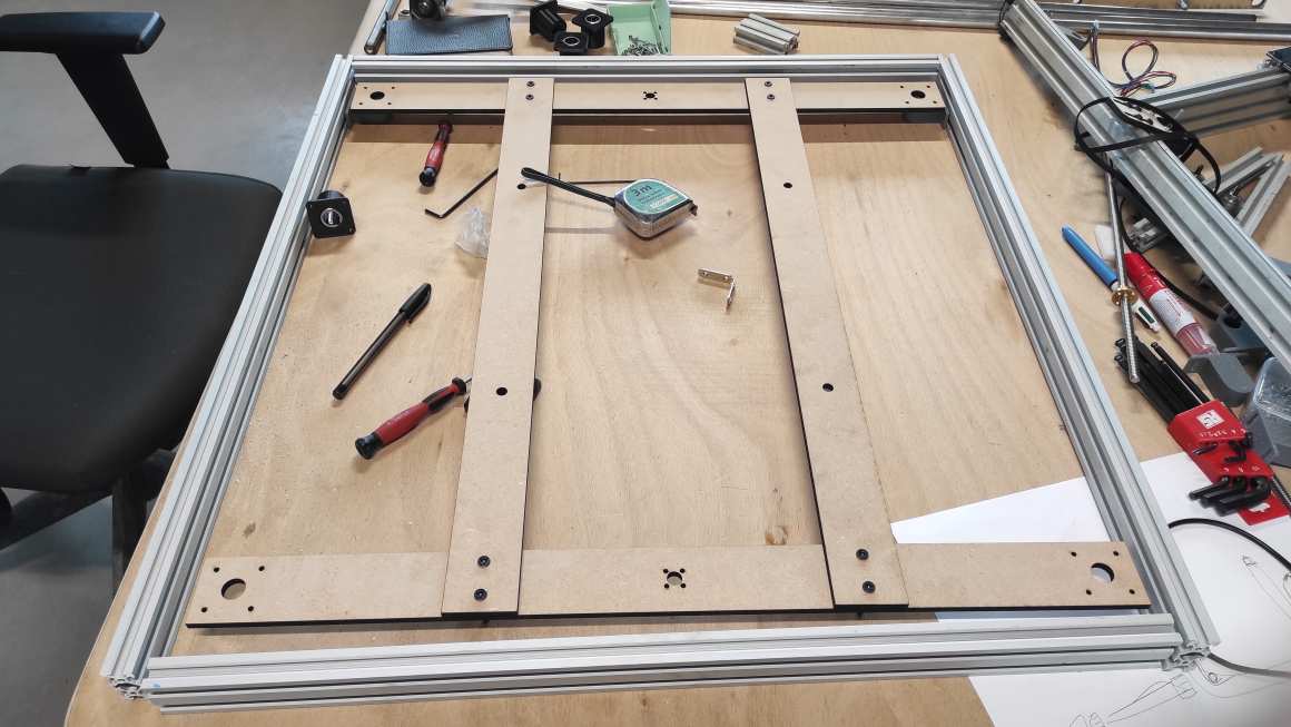
I took measurements of the potential oven that will be used to dimension the printing surface. The width is 39cm, the depth is 40cm, and the height is 44cm.

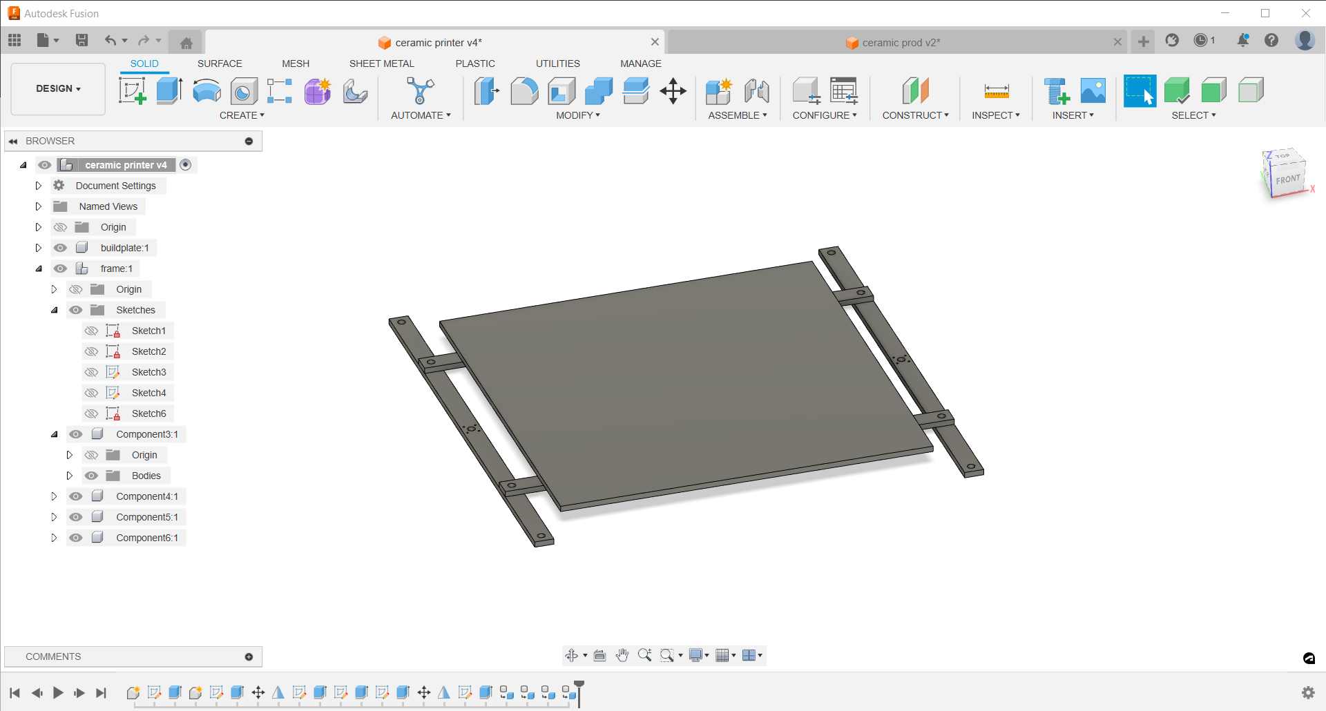
Adel informed us that we need to leave a distance of 1.5cm from the walls during cooking. I opted for a square base of 36cm on each side. For the height, I chose to keep the length of the trapezoidal screws since I don’t yet know what the space requirement will be under the bed. I added an additional safety margin of 1.5 cm. I also created a support on which the bed would rest, which would be attached to trapezoidal screws and axes with ball bearings.
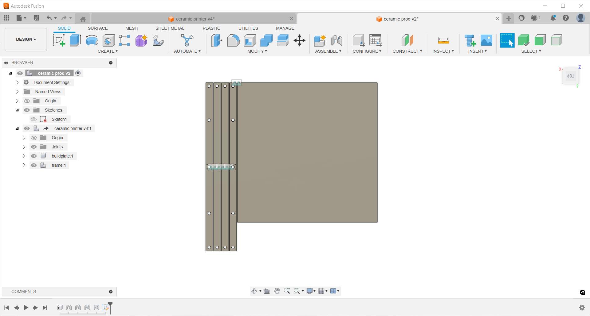
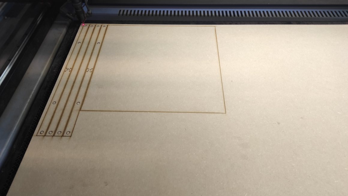
I used a derived model (Fusion360 option) to nest in order to make a first test with the laser cutter. Then we tested it with a simple program using the stepper motors that Jean-Come was testing on his side.

Small parts 1
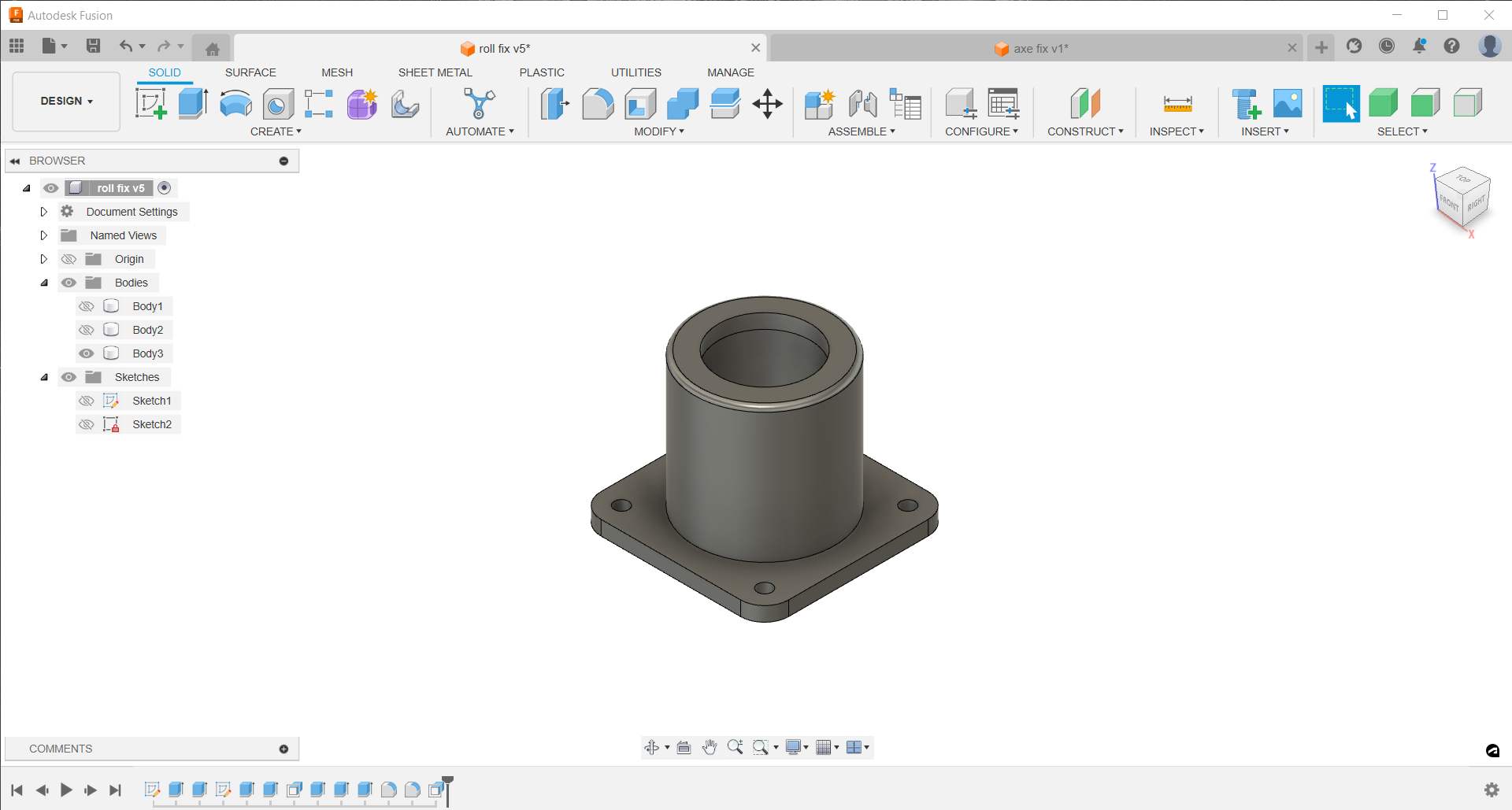
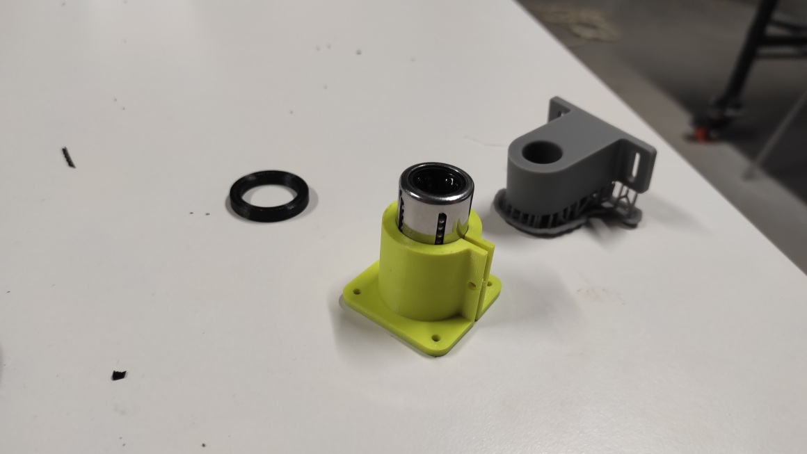
Then I made a piece to encapsulate the bearings and attach the axes to the supports, as well as a piece to fix the axes to the profiles that will form the structure of the printer. I had to change my supports design to fit the new parts.

Outer structure
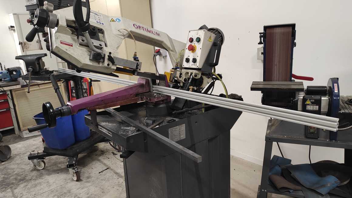
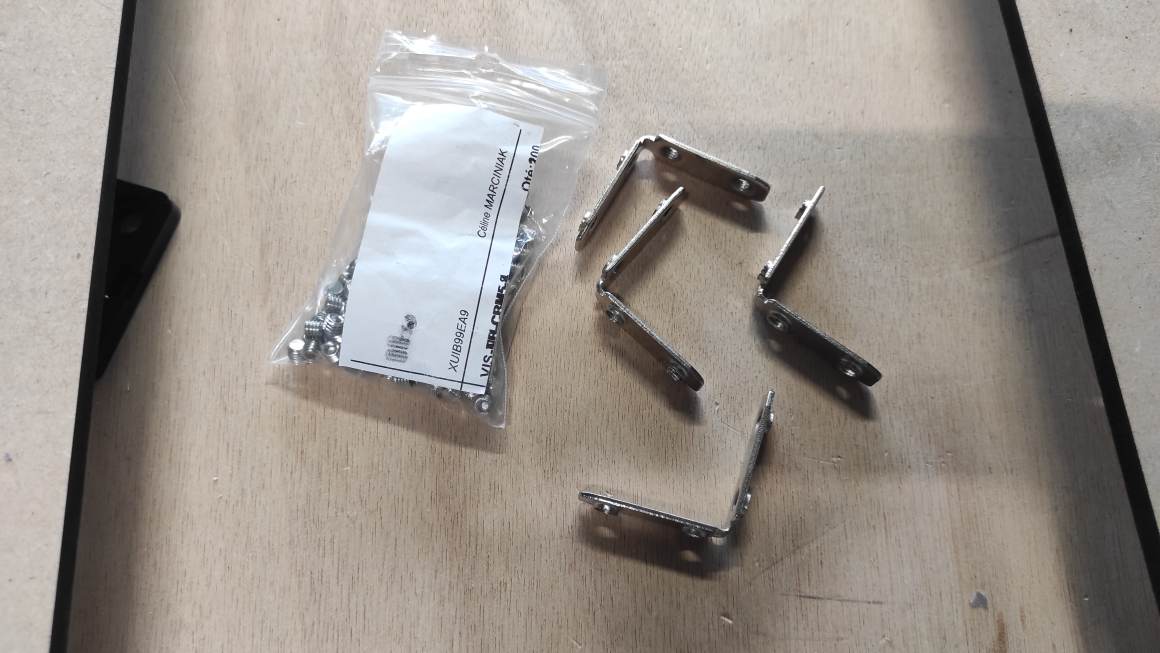
With Jean-Côme making progress on the extruder carriage, I was able to define the necessary margins and start building the outer structure of the machine. I cut some profiles with the band saw and started assembly using small profile brackets.
Small parts 2
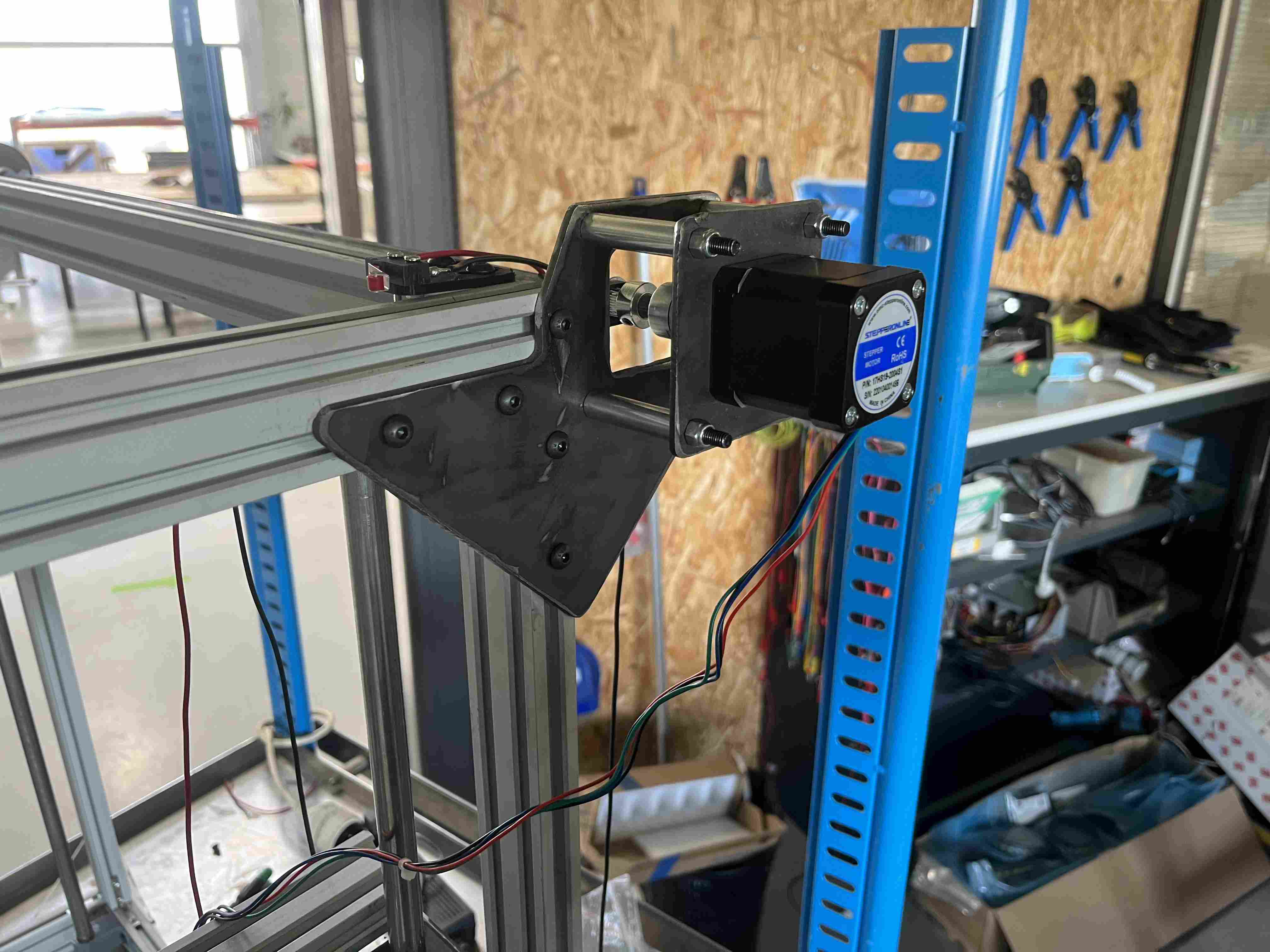
I had to design plates to attach the motors to the profiles, and since the motors were also larger than the profiles, I also had to add feet which I made.
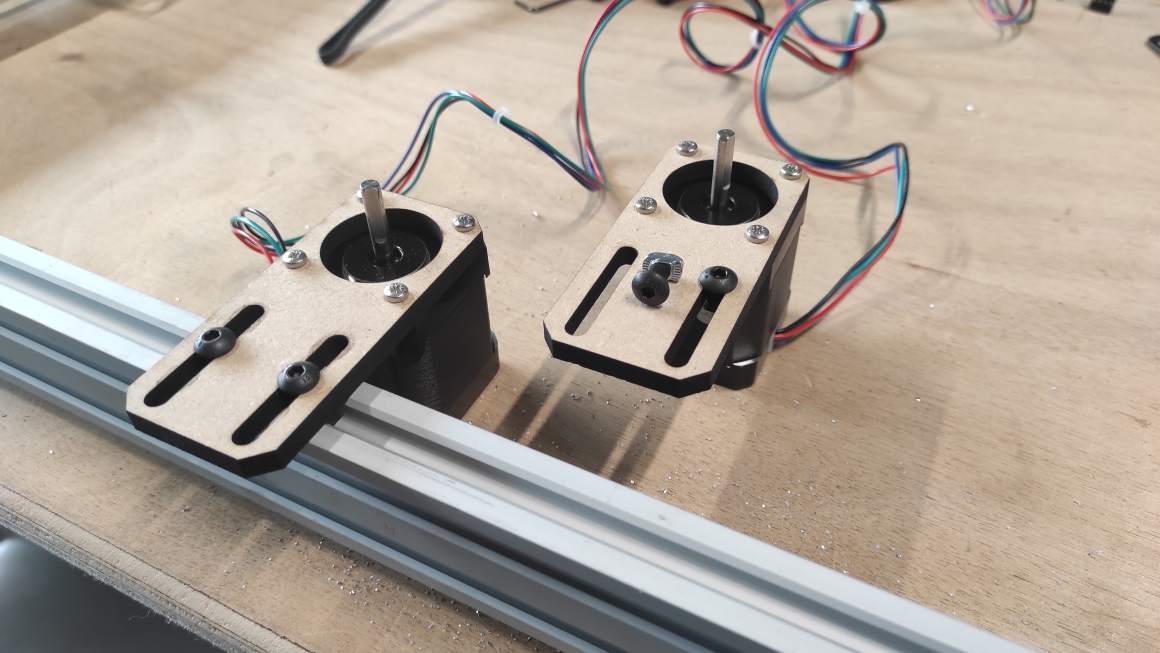

We were able to test the overall assembly with the parts made by Jean-Côme.
Improvement
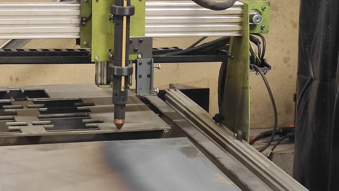
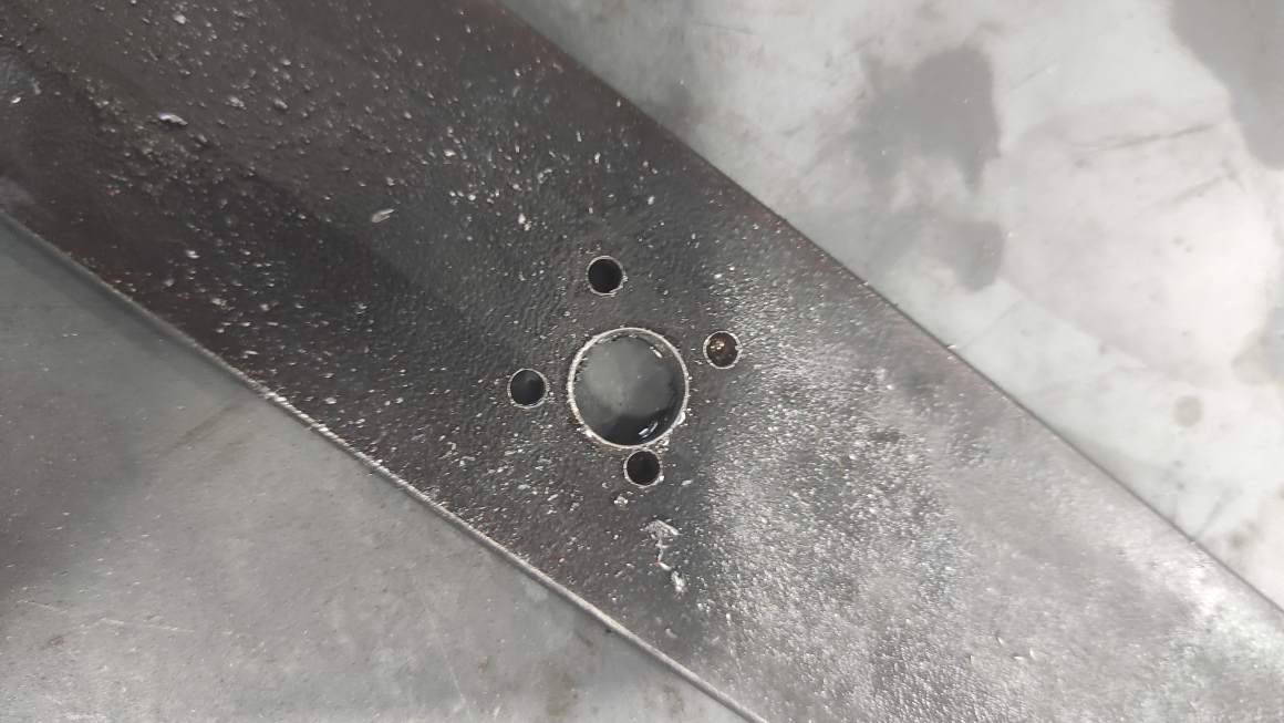
Since the structure lacked rigidity, I added PMMA brackets to each corner. I also tried to make the bed support with the plasma cutter, but the result lacked precision (especially the hole sizes and shapes).
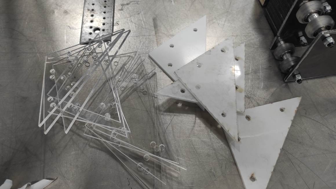

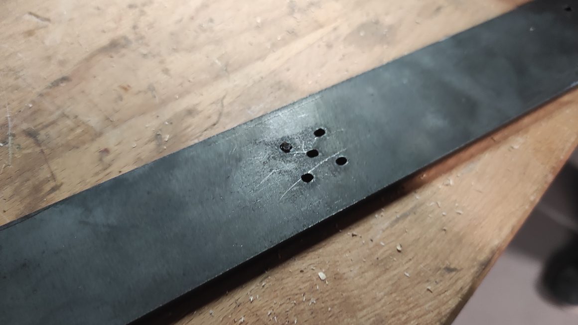
I then tried again by drilling the holes myself with the drill press, but this time I lacked precision. Additionally, the steel seemed too heavy.
I finally opted for profiles and created plates to connect with the axes. To finish, I made the bed and the plates out of 6mm PMMA. I added leveling screws that I had because I had changed them on my 3D printer.


Small parts 3
To finish the assembly, I had to add the endstop sensors micro-switch on the profiles. I had to design various small prints again to place them in relevant locations. I used Farnell Datasheet to have dimension as the size seemed to be standard ZV Lever.


I am not completely satisfied with the results (the one for the X axis is not well fixed enough and the one for the Z axis lacks adjustment possibilities), but I ran out of time to redo them as desired.
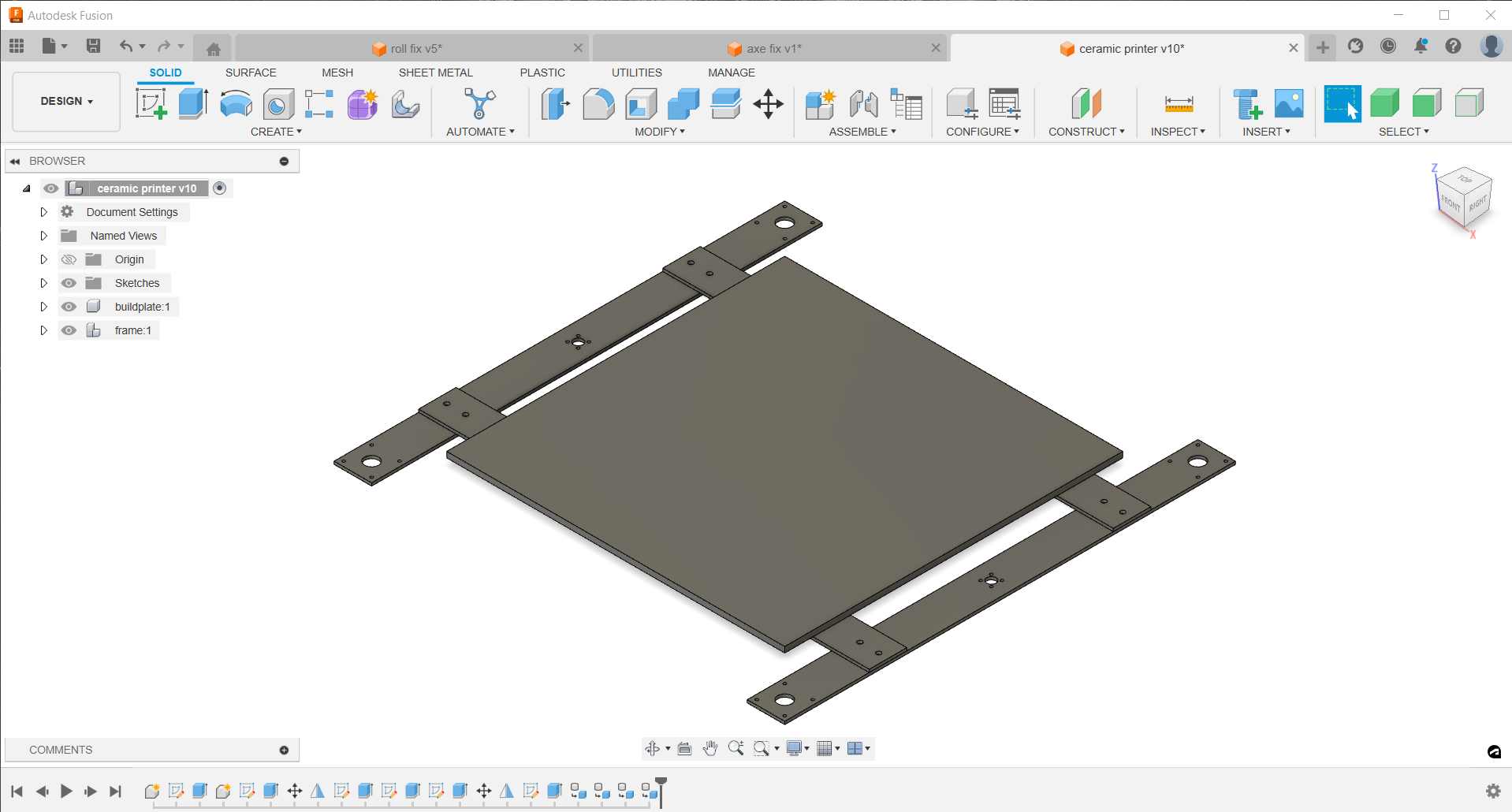
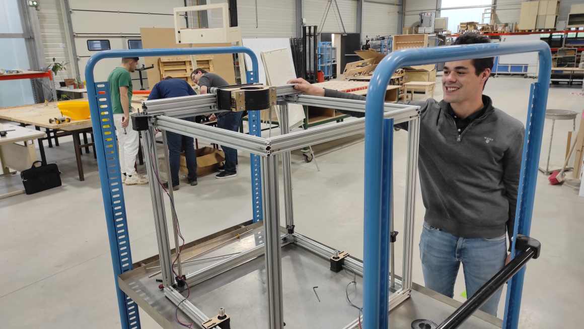
Final design
And here is the complete structure without the extruder.
Class Archive
- Buildplate V1 - MDF prototypes
- Buildplate V2 - PMMA cutted + profiles
- Axe support - stereolithography
- Foot- 3d printed PLA
- PMMA Bracket - PMMA cutted
- Linear bearing support - 3D printed PLA
- Z motor fixation plate - PMMA cutted
- endstop fixation plates - 3D printed PLA
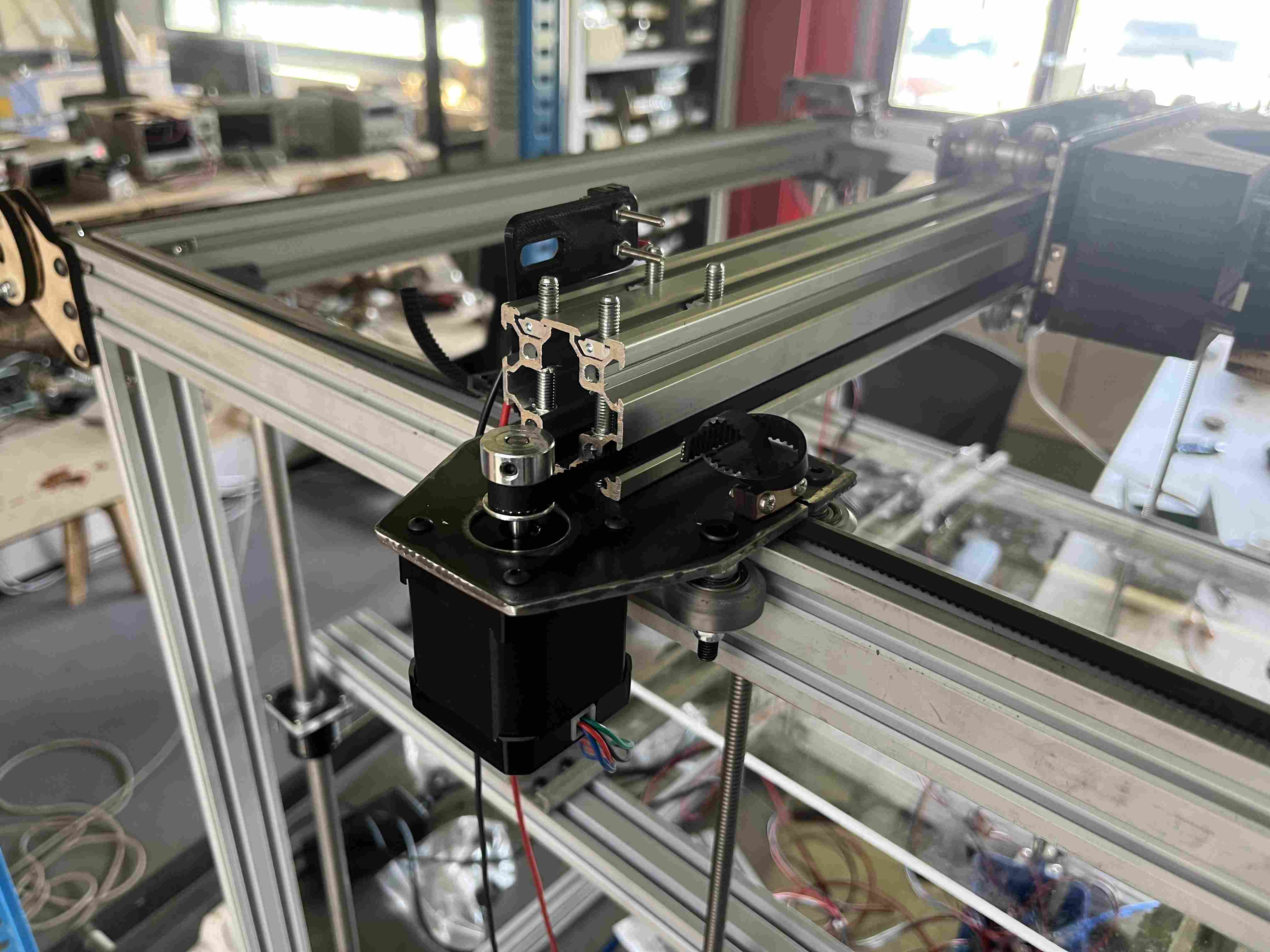
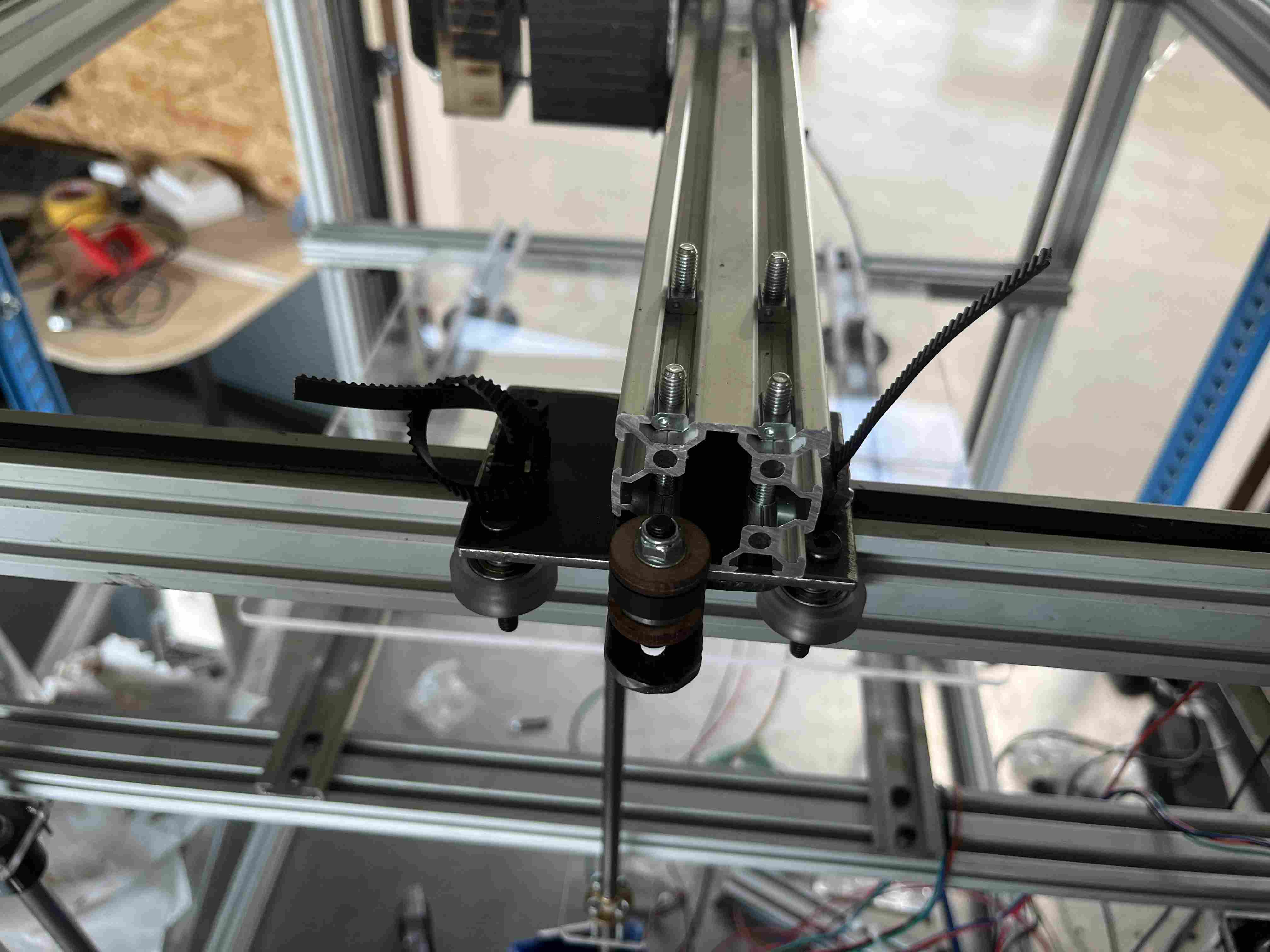
XY Axis (Jean-Côme)
So as not to launch ourselves into the unknown, we decided to take our inspiration from the only printer with a rising platen at Agrilab, the Ender 5 plusCreality. You will therefore notice that a large proportion of our designs are directly inspired by its operation, with adaptations of course to better suit our material, which is clay.
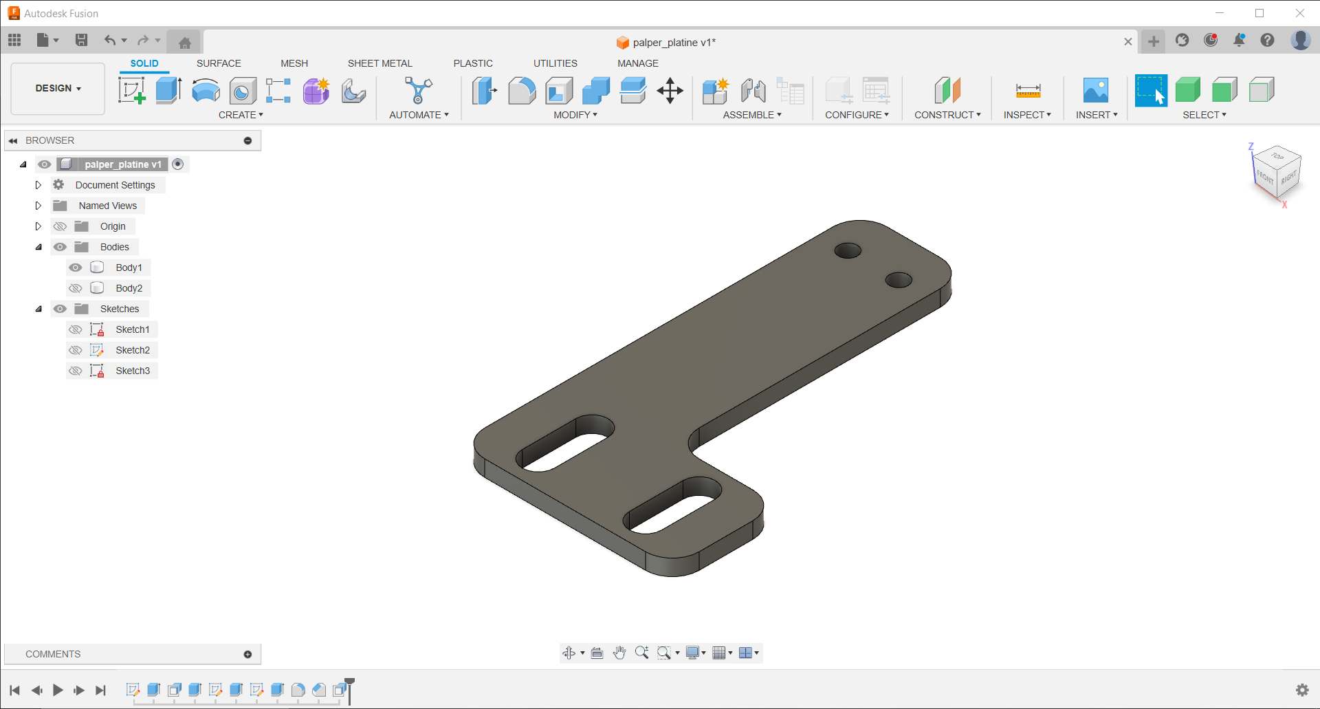
 To get started, I created some designs on Fusion 360. In order to create my plates for the X and Y axis supports, I came up with different designs, taking into account the spacing of the castors so that they pass on either side of the profiles.
I’ve carried out this operation on various parts, including the carriage supporting the extruder and various motor and tensioner supports.
Once I’d modelled my turntables, I started by cutting them out of 3mm MDF. I chose this material because it’s fairly solid and is the same thickness as the steel I used later. I had to make a few adaptations in order to solve problems that I hadn’t considered at the design stage, and that’s where the great advantage lies in carrying out initial tests in wood before moving on to steel, which is more expensive and takes longer to work on. I was right to carry out the initial tests in wood because to case each part, I had to make modifications, which saved me a lot of time.
To get started, I created some designs on Fusion 360. In order to create my plates for the X and Y axis supports, I came up with different designs, taking into account the spacing of the castors so that they pass on either side of the profiles.
I’ve carried out this operation on various parts, including the carriage supporting the extruder and various motor and tensioner supports.
Once I’d modelled my turntables, I started by cutting them out of 3mm MDF. I chose this material because it’s fairly solid and is the same thickness as the steel I used later. I had to make a few adaptations in order to solve problems that I hadn’t considered at the design stage, and that’s where the great advantage lies in carrying out initial tests in wood before moving on to steel, which is more expensive and takes longer to work on. I was right to carry out the initial tests in wood because to case each part, I had to make modifications, which saved me a lot of time.
 Once I had a design that looked good in mdf, I was able to make the metal finishes. To do this, we used the plasma cutter during fabacademy’s machine week in 2022.
 To prepare the file for plasma cutting, I reduced the size of all the holes to 1.8mm, because the machine is constantly being improved and can’t yet cut as precisely and cleanly as with a drill.
To use the laser cutter, we have a computer running the Linux operating system. First, we prepare the dxf files with the Sheetcam which generates a gcode in .tap format that we can then open with the software Linux CNC which controls the cutting machine. Find out more about how to use our cutting machine here and here.
To prepare the file for plasma cutting, I reduced the size of all the holes to 1.8mm, because the machine is constantly being improved and can’t yet cut as precisely and cleanly as with a drill.
To use the laser cutter, we have a computer running the Linux operating system. First, we prepare the dxf files with the Sheetcam which generates a gcode in .tap format that we can then open with the software Linux CNC which controls the cutting machine. Find out more about how to use our cutting machine here and here.
Once my parts were cut out, I took the drill press and drilled the various diameters I needed (3.5, 5, 7) as well as a step drill for the 22.5mm holes where the motors would fit. Once I’d made all my holes, I was able to sand the edges and drill exits to get a smoother, less sharp result. Once I’d made my pieces, I could move on to the assembly stage, for which I used various materials that you’ll find in the list below.
| Composant | Number |
|---|---|
| wheels | 16 |
| screw M5 60mm | 8 |
| screw M5 50mm | 11 |
| screw M5 7mm | 12 |
| Precision washers 1mm | 24 |
| brake nuts m5 | 24 |
| hammer nuts | 20 |
| eccentric spacer m5 | 8 |
| 6mm spacer | 8 |
| 9mm spacer | 4 |
| 40mm spacer | 4 |
| Steel 3mm | |
| MDF 6mm | |
| MDF 2mm | |
| bearings 16mm | 6 |
| bearings 30mm | 1 |
| gt2 belts | 2 |
| 8mm steel axle | 1 |
| Stepper motor Nema 17 | 2 |
| gt2 8mm gear | 2 |
| gt2 5mm gear | 1 |
| 5mm threaded rod | 1 |
| washers | 16 |
| profile 40X40mm | 730mm |
| profile 20X40mm | 2,6m |
Once all these different elements were assembled, we were able to mount them together. In my case, my designs were only fixed using castors.
Tube support (Jean-Côme)
To hold our clay tank, I made a support to hold our tube firmly on our X-axis carriage. As the tubes we have have a large diameter, we had to make a fairly long carriage that takes up a lot of space. The support is also very large. I produced a design on Fusion 360 to hold our tube on our support. As for the height of our concption, I based it on the height of the patina. As the part was very important, it required 20 hours of printing time, and as I didn’t have the time, I decided to cut it into slices and cut it with the laser cutter in 6mm MDF, which saved me precious time. To prevent the layers coming unstuck during drilling and clamping, I replaced the last parts of the flat faces with a piece in the opposite direction.
If you would like to reproduce any of the pieces, you can do so by clicking on the following links
| Localisation | Components |
|---|---|
| Y axis | Single trolley |
| Y axis | Motor X trolley |
| Y axis | Support plate |
| Y axis | Motor plate |
| Y axis | Bearing support |
| Y axis | Bearing support |
| Y axis | Tensioner |
| X axis | Extruder trolley |
| X axis | tensionner |
| Belts | tensionner |
| Extrudeur | Tube support |
Extrusion, the head (Pol-Emile)
To make the head we were inspired by the work of bryancera and Adel Kheniche. We have at our disposal a PMMA tube 900mm in diameter, 3mm thick and 400mm high, as well as an 8mm rod and a nut compatible with it.
We had to model the various parts. For this part, they were modelled using FreeCad. The parts are :
- The nozzle
- The piston
- The motor gear
- The gear on the screw
- The motor support
- The connection between the tube and the screw gear
All these parts were printed in PLA using 3D printers. In a future version, we plan to use nylon for the gears to improve their mechanical strength.
The nozzle

For the nozzle, the main challenge was to make a part that could be connected to the tube without letting any material through, and that was interchangeable. To hold it in place, a system of bolts has been inserted into the PLA, and the screws start on the outside and are inserted inside. The inside has a concave shape to facilitate the flow of the material and the hole releasing the material is also funnelled for the same reasons.
The piston
The purpose of the piston is to push the material and transmit the force given to it by the rod. It is convex in shape to distribute the forces as evenly as possible. To make it more resistant, we filled it with more material (30%) and defined it finely. Two O-rings have been placed on the edges to prevent the material from passing behind the piston.
Gears
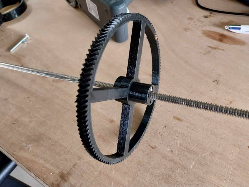
In order to have sufficient force, the documentation we used indicated that the ideal ratio was between 1:20 and 1:30. Initially we used a ratio of 1:20, which gave us a tiny gear on the motor and a huge one on the rod. However, it turned out that the gears weren’t actually big enough to cover the distance between the centre of the motor and the centre of the tube, so we switched to a 1:22 ratio.
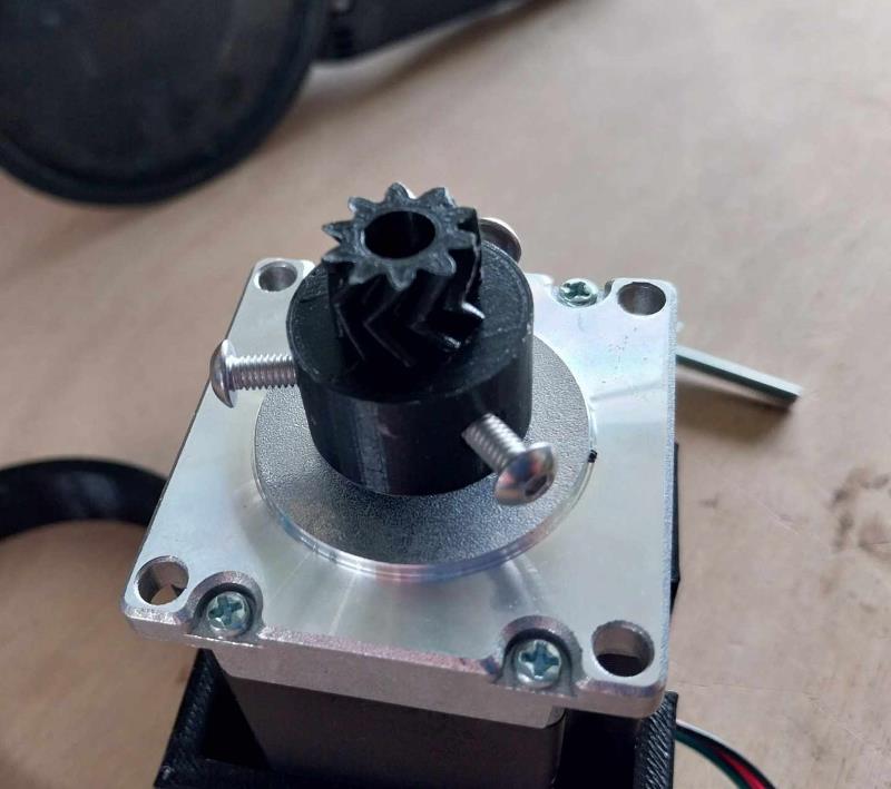
To attach the gears we have two systems: on the motor a system of nuts inside the PLA and screws that press on the motor shaft. And for the screw gear, a fixing with the nut matched to the shaft.
The motor support

The main problem here is that it’s quite complex to know the precise position of the motor, because it depends on the precision with which the gears will be printed. To overcome this problem, we’ve created an adjustable position using a screw. The motor is held to the tube with a clamp.
The connection between the tube and the screw gear
This part is the most complex, because this is where we have to play with the degrees of freedom to constrain the parts as we wish. We want the screw to exert downward pressure, so we want it to translate rather than rotate. We therefore need to block it in every other direction. To counteract the pressure pushing back the motor and the screw, the screw gear is embedded in the coupling. The screw and nut are integral.

Files
Here you can find the STL nozzle, piston, top, motor, engineMount1, engineMount2, gear
Electronics (Jean-Côme)
In order to control our printer, we have chosen to use nema 17 stepper motors from stepper online for controlling the X, Y and Z axes of our printer. For the extrusion part, we chose to use a larger motor in order to have enough force to push the clay.
In order to test all the engines by activating them, I used the code below which I found on this page. We carried out the usual assembly except for the Z axis, where we added an extra driver to control the second Z axis motor. In order to control the drivers A4988, we’re using a shield connected to an Arduino UNO.
The code I used to test the stepper motors is as follows:
const int enPin=8;
const int stepXPin = 2; //X.STEP
const int dirXPin = 5; // X.DIR
const int stepYPin = 3; //Y.STEP
const int dirYPin = 6; // Y.DIR
const int stepZPin = 4; //Z.STEP
const int dirZPin = 7; // Z.DIR
int stepPin=stepYPin;
int dirPin=dirYPin;
const int stepsPerRev=200;
int pulseWidthMicros = 100;     // microseconds
int millisBtwnSteps = 1000;
void setup() {
    Serial.begin(9600);
    pinMode(enPin, OUTPUT);
    digitalWrite(enPin, LOW);
    pinMode(stepPin, OUTPUT);
    pinMode(dirPin, OUTPUT);
    Serial.println(F("CNC Shield Initialized"));
}
void loop() {
    Serial.println(F("Running clockwise"));
    digitalWrite(dirPin, HIGH); // Enables the motor to move in a particular direction
    // Makes 200 pulses for making one full cycle rotation
    for (int i = 0; i < stepsPerRev; i++) {
            digitalWrite(stepPin, HIGH);
            delayMicroseconds(pulseWidthMicros);
            digitalWrite(stepPin, LOW);
            delayMicroseconds(millisBtwnSteps);
    }
    delay(1000); // One second delay
    Serial.println(F("Running counter-clockwise"));
    digitalWrite(dirPin, LOW); //Changes the rotations direction
    // Makes 400 pulses for making two full cycle rotation
    for (int i = 0; i < 2*stepsPerRev; i++) {
            digitalWrite(stepPin, HIGH);
            delayMicroseconds(pulseWidthMicros);
            digitalWrite(stepPin, LOW);
            delayMicroseconds(millisBtwnSteps);
    }
    delay(1000);
}
Thanks to this code, I was able to control the operation of my motors and make them work.
Calculating VREF
Our motor drivers have a potentiometer for adjusting this. But you have to calculate it first. To do this, I’ve found the following formula: VREF = Maximum motor current(Amps) * 8 * Potentiometer resistance(Ohms)
| Parameter | Value |
|---|---|
| maximum curent | 2A |
| Resistor | 0.05 Ohms |
| VREF | 0.8V |
Using these values, not all the motors worked, some made noise and shook, so I adjusted the motors while they were running to determine the correct value. Once I had a working system, I didn’t change the values again.
GRBL
To make our printer work, we originally decided to use the Marlin which is very well known. However, we were running late and decided to use the printer with the GRBL much easier to use. Simply download the zip file, unzip it, open it and paste the folder grbl in the Arduino>libraries file on our computer. We can then go to the grbl > examples > grblUpload and open the .ino file with the Arduino IDE. You can then upload it to your Arduino UNO.
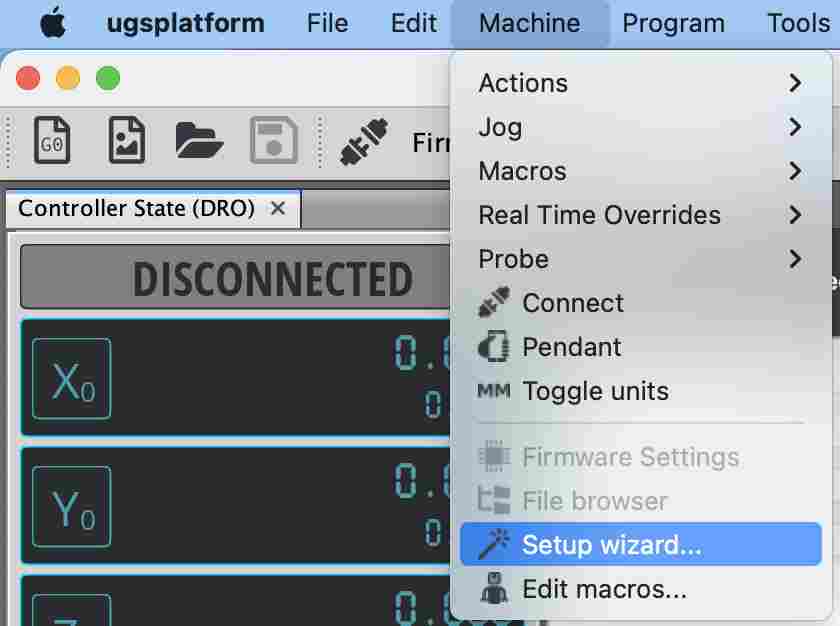
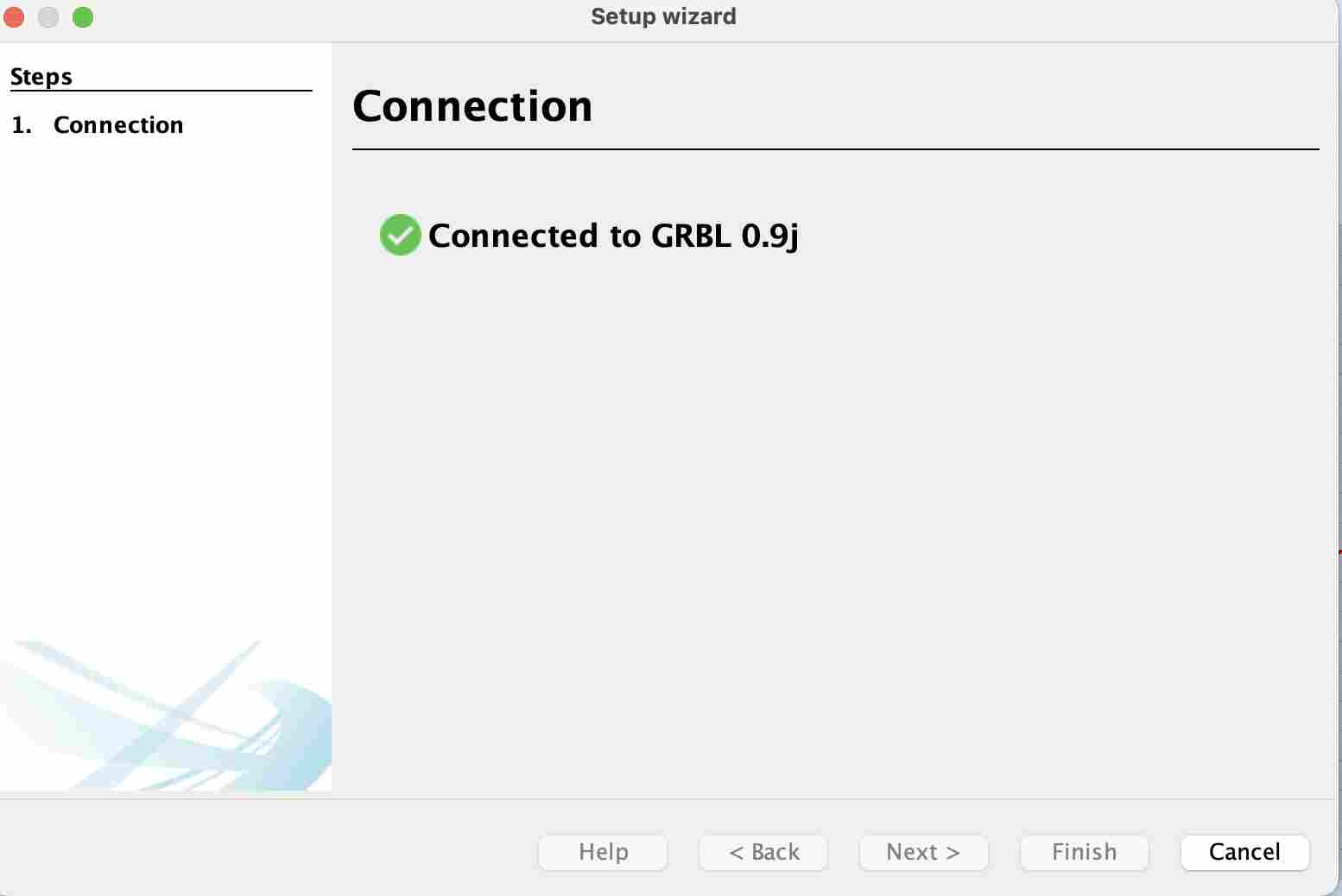
Once the Arduino has been configured with grbl, you can download Universal GCode Sender which will allow us to control the printer. To use it, open it and go to tools then Setup wizard. A window will open where you can select different parameters and try to connect.
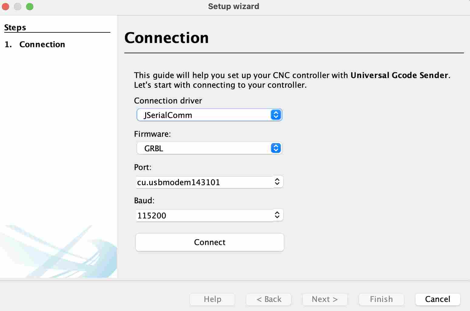
Once the contact has been made, we receive a message saying that it has been successfully connected and we can then start configuring the printer.
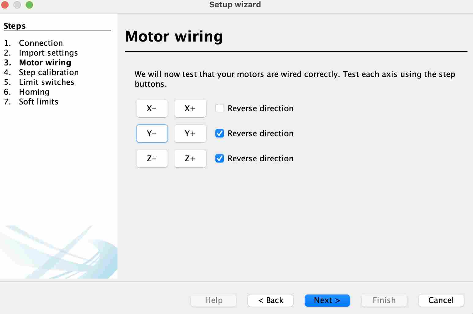
We can then check the engines by checking their direction and whether they move well or whether there are any electronic problems.
I then stopped for lack of time at the calibration stage, here are the values I had determined for our different
| Axe | Number of motor steps per revolution | Number of thread/belt pitches per revolution | Value(step/mm) |
|---|---|---|---|
| X | 200 | 40 | 5 |
| Y | 200 | 40 | 5 |
| Z | 200 | 2 | 100 |
To arrive at these results, I used the following formula: Value(step/mm) = Number of motor steps per revolution / Number of thread or belt pitches per revolution
BOM (Alexis)
Profiles
| Quantity | Type | Dimensions | Comments |
|---|---|---|---|
| 2 | 10*30mm profile | 550mm | Support Plate |
| 1 | 40*40mm profile | 730mm | X Axis |
| 2 | 20*40mm profile | 630mm | Support Plate |
| 4 | 20*40mm profile | 650mm | Height |
| 4 | 20*40mm profile | 652mm | Width |
| 4 | 20*40mm profile | 692mm | Depth |
Brackets and Supports
| Quantity | Description | Dimensions | Comments |
|---|---|---|---|
| 32 | Profile brackets | ||
| 14 | 10*10mm PMMA brackets | 6mm transparent | |
| 3 | PLA Fixations (Extruder, Endstop) | ||
| 5 | Steel plates | 3mm | Variable size |
| 1 | PMMA Plate | 390*390mm | |
| 6 | PMMA Plates | 40*80mm | |
| 2 | PMMA Plates | 42*74mm | |
| 8 | Resin axis supports | ||
| 1 | PLA Piston Support | ||
| 4 | PLA Bearing Supports | ||
| 1 | PLA Motor Support |
Screws and Nuts
| Quantity | Description | Dimensions | Comments |
|---|---|---|---|
| 120 | M5 Set Screws | ||
| 56 | M5 Countersunk Screws | 8mm | |
| 16 | M5 Countersunk Screws | 8mm | |
| 25 | M5 Countersunk Screws | 12mm | |
| 8 | M5 Countersunk Screws | 10mm | |
| 4 | M4 Countersunk Screws | 35mm | |
| 8 | M3 Screws | 30mm | Brass nut fixation |
| 8 | M3 Countersunk Screws | 8mm | |
| 8 | M3 Countersunk Screws | 8mm | Motor fixation |
| 6 | M3 Countersunk Screws | 5mm | Motor fixation |
| 3 | M4 Screws | 16mm | |
| 3 | M5 Screws | 30mm | |
| 2 | M5 Hexagonal Screws | 50mm | |
| 8 | M5 Hexagonal Screws | 50mm | |
| 6 | M5 Hexagonal Screws | 50mm | Shorter possible |
| 6 | M5 Countersunk Screws | 30mm | |
| 16 | M5 Countersunk Screws | 8mm | |
| 4 | M6 Hexagonal Screws | 20mm | |
| 8 | M3 Nuts | ||
| 8 | M5 Nuts | ||
| 8 | M3 Nuts | ||
| 4 | M5 Nuts | ||
| 8 | M5 Excentric Nuts | ||
| 29 | M5 Lock Nuts | ||
| 4 | M5 Standard Nuts | ||
| 6 | M6 Nuts | ||
| 122 | M5 Hammer Nuts | ||
| 4 | M5 Threaded Rods | 120mm | |
| 6 | M2.5 Nuts | ||
| 16 | M2.5 Lock Nuts | ||
| 3 | M4 Nuts | ||
| 4 | M4 Nuts | ||
| 8 | M5 Nuts | ||
| 9 | M5 Spacers | 5mm | |
| 4 | M5 Spacers | 8mm | |
| 4 | Rubber Spacers | Levelling | |
| 28 | Precision Washers | 1mm |
Rods and Bearings
| Quantity | Description | Dimensions | Comments |
|---|---|---|---|
| 4 | 14mm Rods | 670mm | |
| 1 | 8mm Rod | 760mm | |
| 3 | M8 Brass Threaded Rods | 600mm | 2mm pitch, 1 missing |
| 1 | Trapezoidal Threaded Rod | 600mm | |
| 4 | Ball Bearings for Axis | ||
| 38 | Ball Bearings | ||
| 3 | Flexible Motor Supports | ||
| 3 | Toothed Wheels | ||
| 16 | Wheels |
Others
| Quantity | Description | Dimensions | Comments |
|---|---|---|---|
| 1 | PLA Nozzle | ||
| 3 | 1600mm Belts | ||
| 2 | PLA Gears | ||
| 1 | PLA Piston | ||
| 1 | PMMA Tube | 90mm diameter, 3mm thickness, 435mm length |
Electronic
| Quantity | Description | Dimensions | Comments |
|---|---|---|---|
| 1 | Arduino Uno | ||
| 1 | CNC Shield | ||
| 4 | Drivers | ||
| 3 | ZVlever Endstop Switches | ||
| 4 | Nema 17HS19 Motors | ||
| 1 | Nema 23HS30 Motor |