Week 08 - Electronic design
Group assignment :
- use the test equipment in your lab to observe the operation of a microcontroller circuit board
- send a PCB out to a board house
test equipment
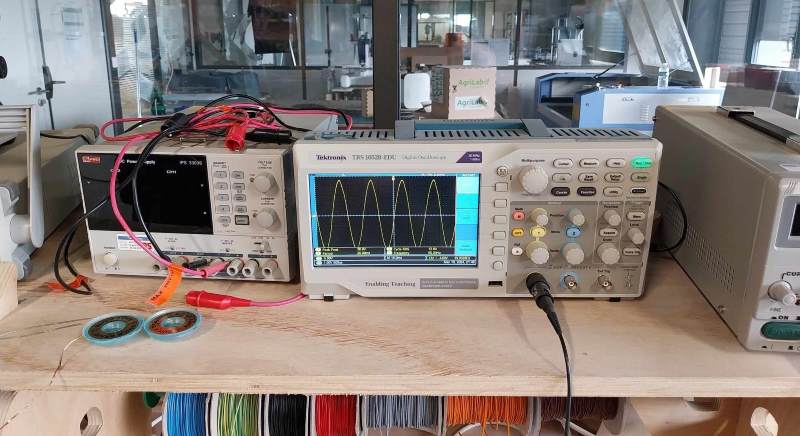
To test our boards, we used an oscilloscope with the help of Luc HANNEUSE. The aim was to see the voltage variations inside a board whose LEDs were flashing. Initially, we had a few problems, not least because the oscilloscope was incorrectly adjusted.
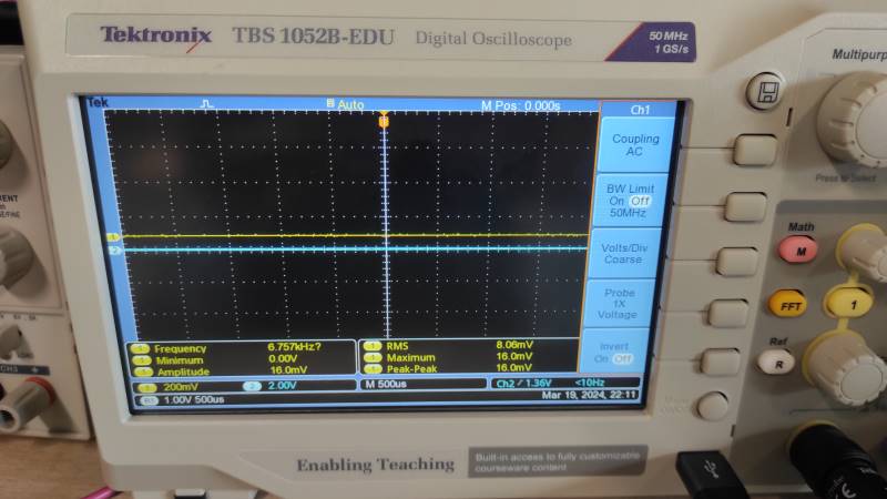
To set the correct reading range, we adjusted the hard buttons on the screen and the two buttons 1 and 2 (yellow and blue). To read the electrical current (from terminal 3.3V to GND), we used the scales to check that the current was indeed 3.3V and sinusoidal.
We then blinked an LED, taking the current between the LED and the resistor, and measuring the return to GND.
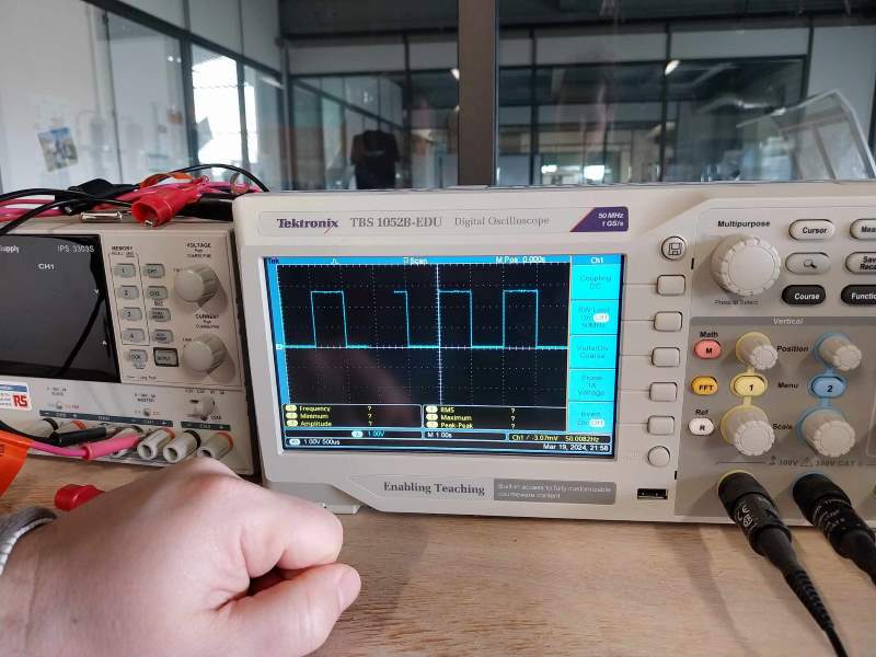
We then blinked two LEDs intermittently, adjusting them so that the blue curve took the first LED and the yellow curve the second.