Week 11 - Input devices
group assignment
- probe an input device’s analog levels and digital signals
Rotary encoder signals
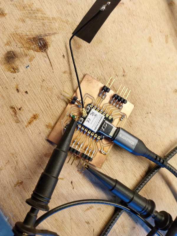
As I was testing programming a rotary encoder, I decided to probe it with an oscilloscope to visualize the digital signals of the 2 switch ccurring when turning it.
I connected CLK pin to the Channel 1 (yellow) and the DT pin to the Channel 2 (blue). When we turn the rotray encoder we see the signals going low for a moment with a slight timing difference.
we can see on this picture, DT changing before CLK when direction is clockwise and CLK before DT when direction is counter-clockwise.


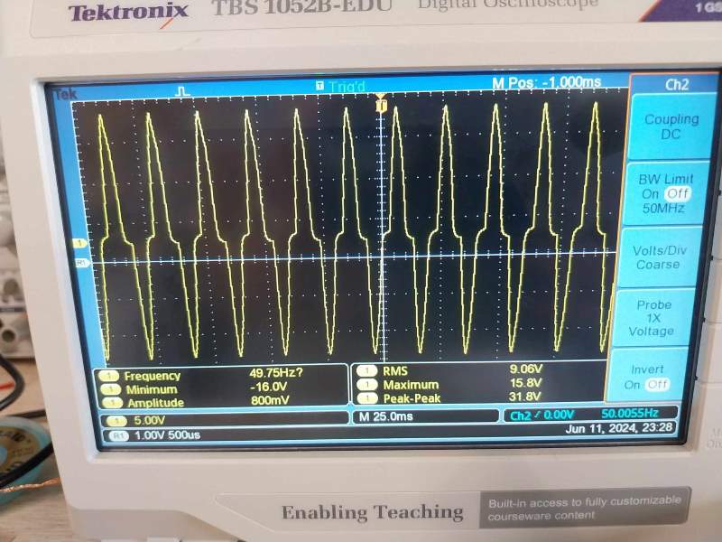
Other signals
We try another signal with the oscilloscope and a temperature sensor. We obtain this curve, which represents the voltage sent to the microcontroller.