Week 04 - Electronics Production
This page serve for documenting our FabAcademy’s group assignement.
Group Assignment :
- characterize the design rules for your in-house PCB production process
- send a PCB out to a board house
Design rules
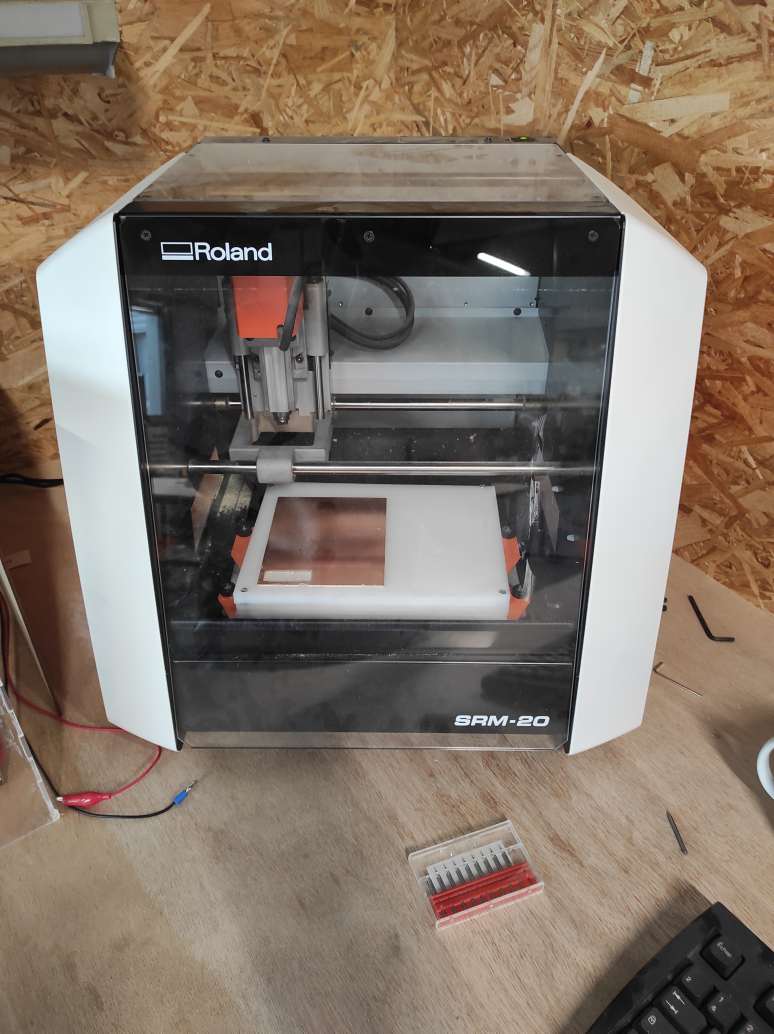
To characterize the design rules for our in-house PCB production process, we decided to try different end mills on our Roland SRM-20.
Preparing files
Getting the traces and the interior linetest PNG files from the course documentation, we used mods project.
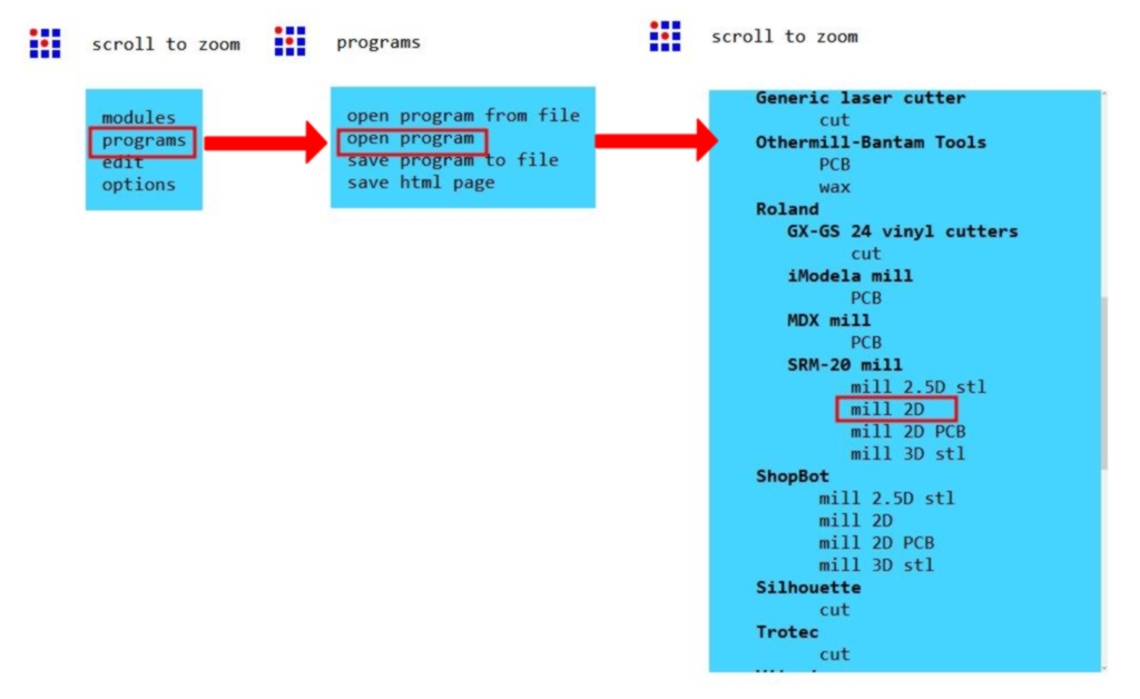
At first, youve to right-clicked to open the menu, then choose programs > open program and finally choose the milling machine and the program corresponding. For us, it was the Roland SM-20 mill 2D.
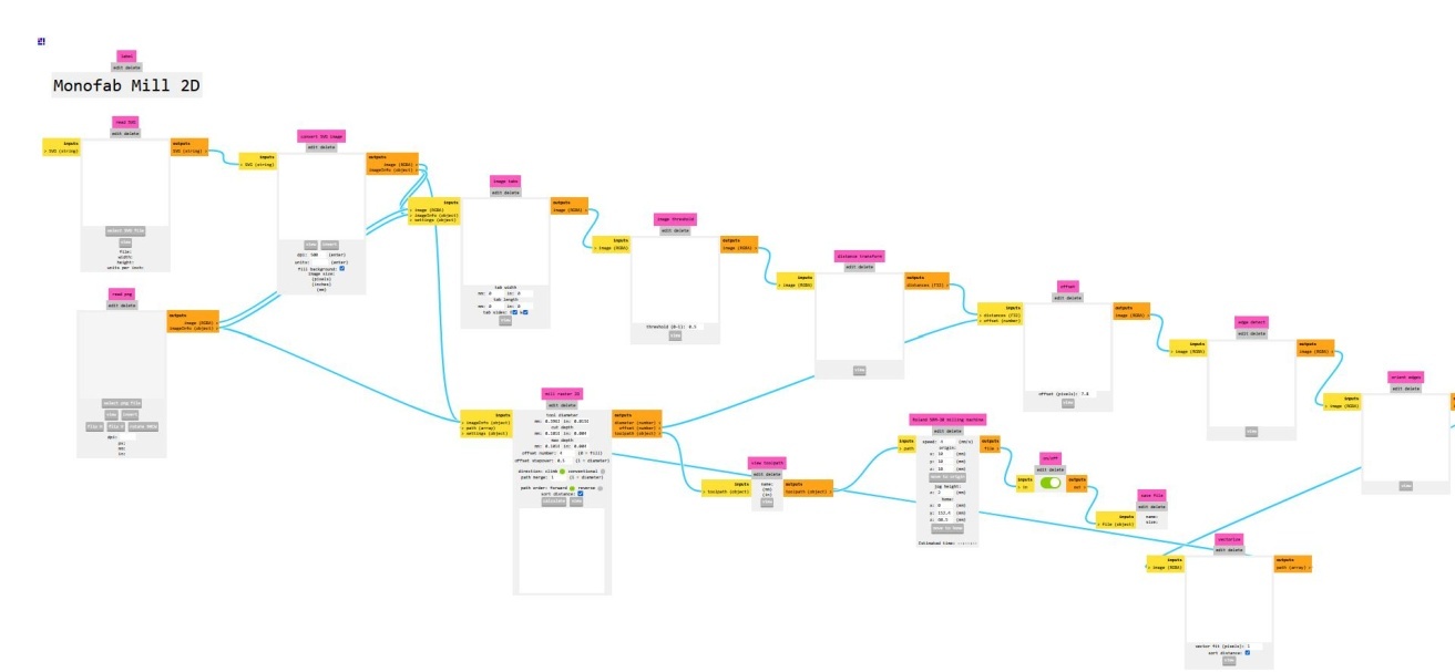
It opens a big tree where you need to enter the settings to create your work file.
We will need two files, one for the traces and one for the cutting, cause we don’t use the same end mill.
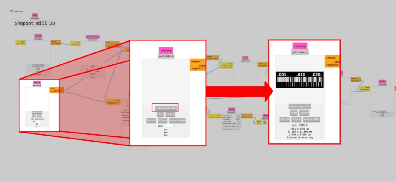
First, you need to upload a SVG or a PNG of your circuit path.
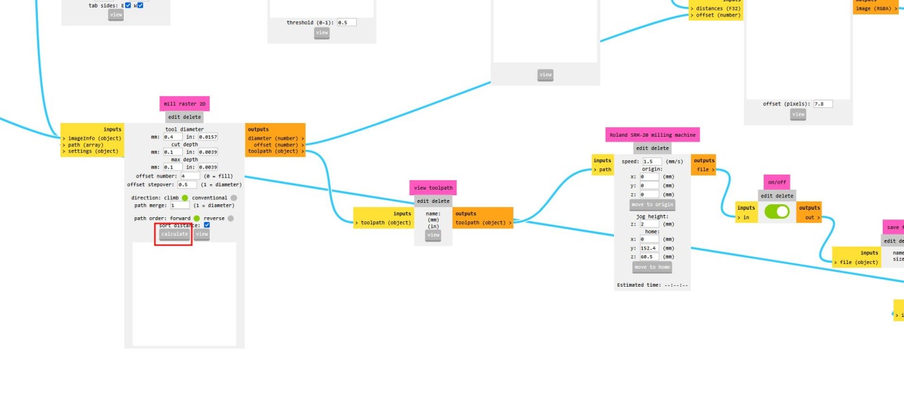
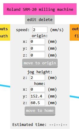
Then you add the end mill properties for creating the path in the end mill Raster 2D box. We use a 0.4 mm flat end mill with a cut depth of 0.1 mm. The offset is set at 4 with a stepover of 0.5, meaning that the end mill will make 4 times the traces around the sketch if it has the space for it. You also need to add the milling machine properties, the speed of movement, here set as 1.5 and the origin. The job height and home can be let as it is.
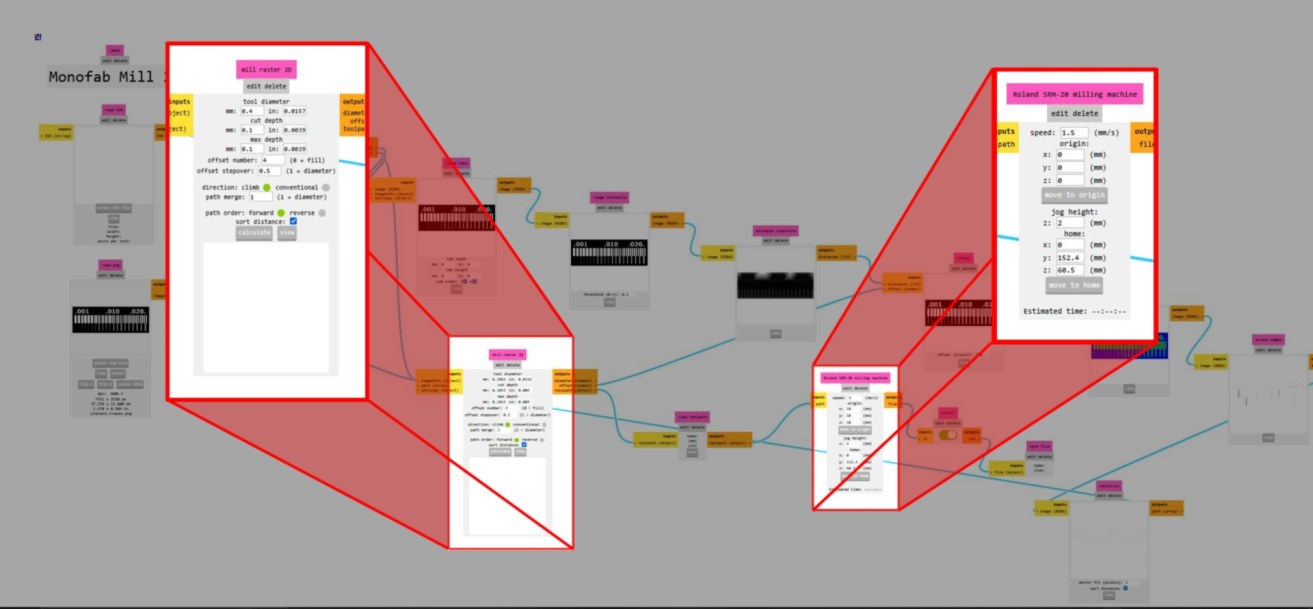
Once the parameters are set, you can click calculate under the mill raster 2D box. It will automatically download the file in the right format (RML for for this machine).
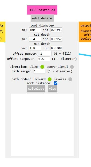
Use the same process for the interior : - Import the PNG file, - add the parameters : To cut the PCB, we use a 1 mm flat end mill, with a cut-depth of the 0.4 mm to a max depth of 1.8 mm (the pcb’s thickness is 1.5 mm). The offset is set to 1. The step is not taken into account in this case. The speed can be increased to 2.
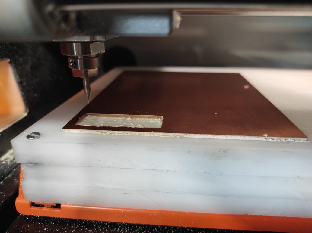
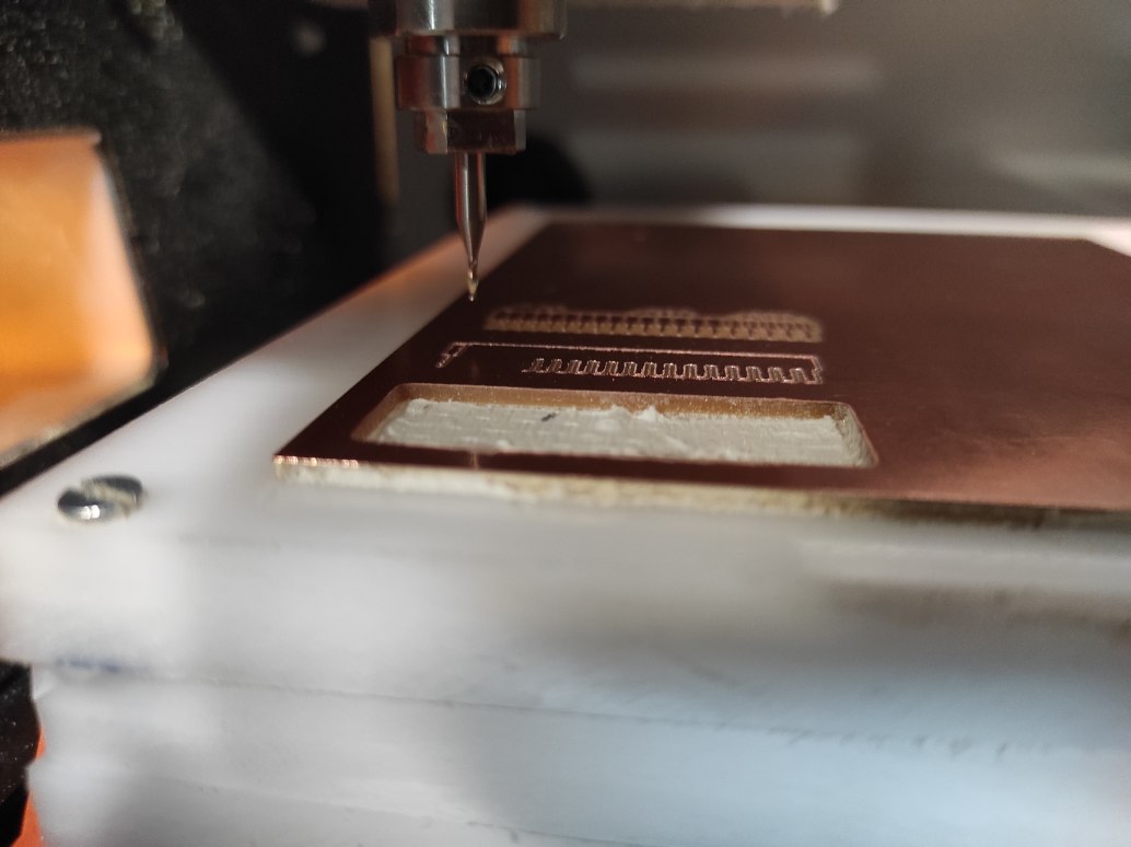
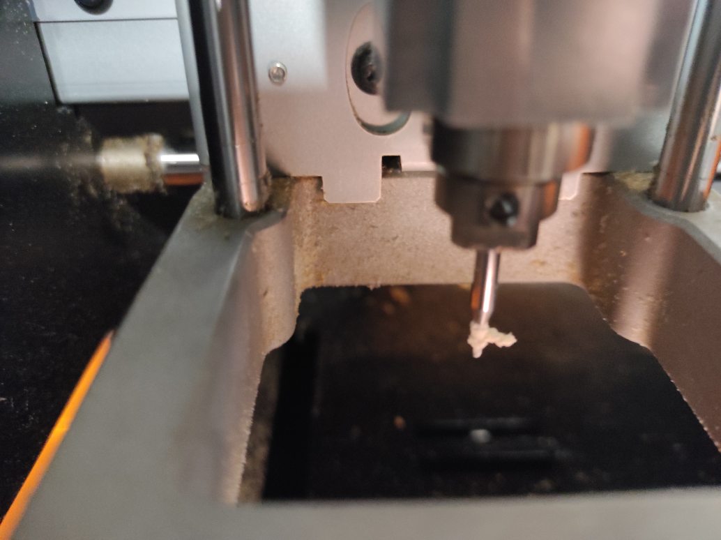
Preparing machine
As described above, we use a Roland SM-20 milling machine with, for the first test, a 0.4 mm flat end mill.
Fisrt, the Copper Clad Laminate (CCL) has to be fixed on the sacrificial layer with double-sided tape. This time, the CCL was already fixed by our instructor for the exemple.
The end mill has to be screwed in the collet.
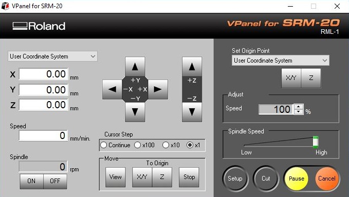
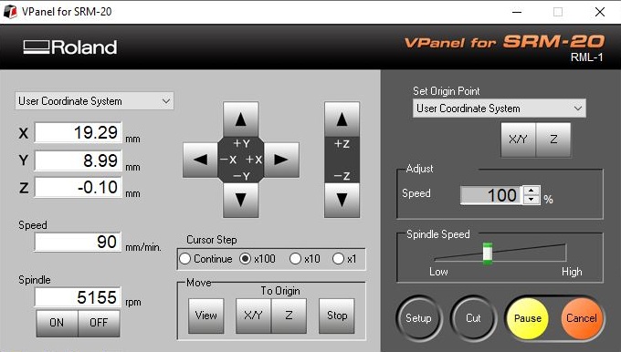
Using the machine’s dedicated software (Vpanel) controls, the end mill is placed over a chosen origin. You can choose the movement step : continue, x100 (1mm), x10 (0.1mm) or x1 (0.01mm).
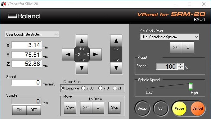
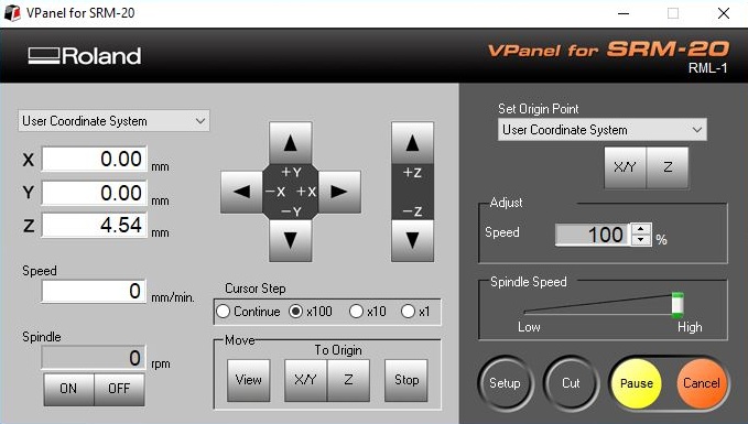
You can validate the position by hitting the XY Origin on the right side of the panel. The position X and Y now turn to 0.
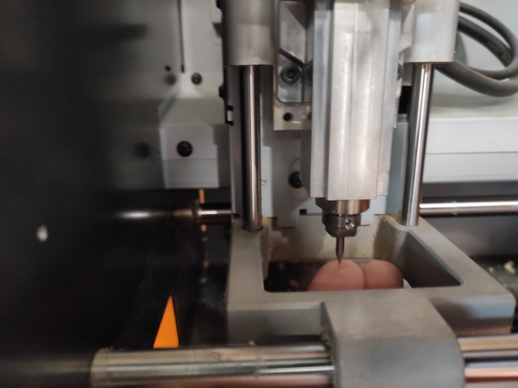
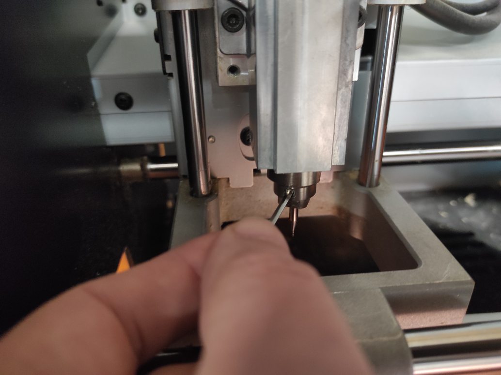
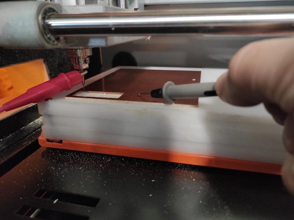
Then you have to set the Z origin. To do so, you have to approach the end mill near the surface of the CCL, then unscrew the collet to make the end mill slip a little (controlled by touching it) till the surface.
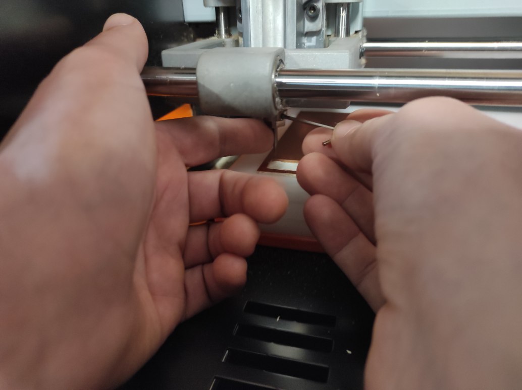
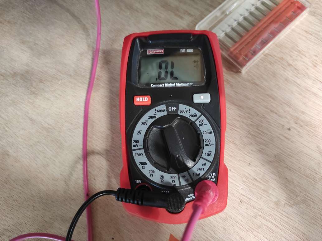
You can screw the collet again and verify the contact between the end mill and the CCL with a multimeter and the continuity test fonction. To do so, put a contact on the mill and the other on the CCL. The multimeter should beep if contact is made. If not you can approach step by step the end mill with the x1 step until you hear a beep. This technique is called probing.
Finally, you can validate the Z origin by hitting the button on the right side of the Vpanel software. The Z coordinates turne to 0.
Importing Files
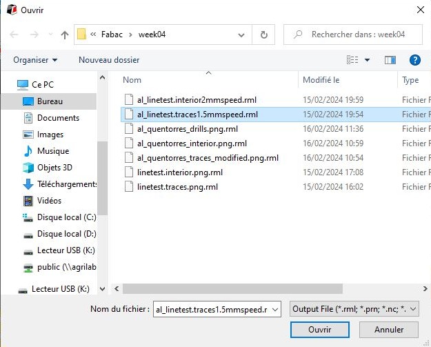
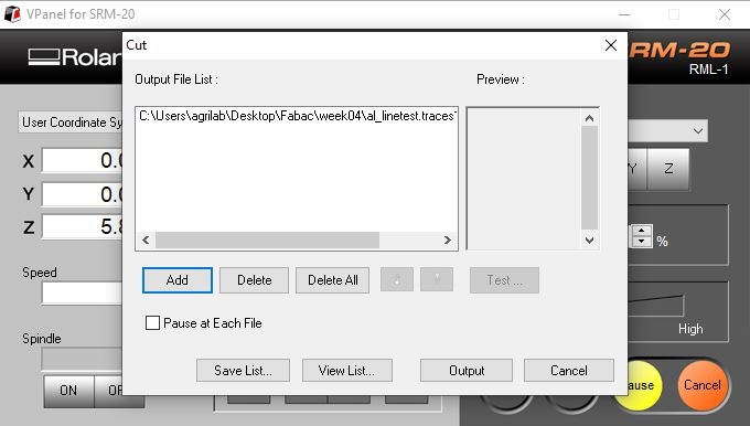
You can import your RML file by hitting the cut button. It will open a new window with the files currently in the machine as en “Output File List”.
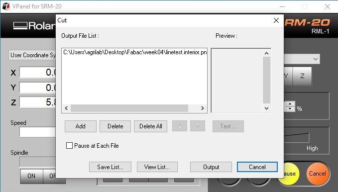
You should delete all the files then add the file you want to mill. You can now see your file in the output file list. If you hit the output button, the machine will start milling
During the milling you can check the position, the speed and the spindle, and eventually adjust the speed on the right side of the panel.
Once the traces are done, you have to change the end mill, reset the Z origin with the new end mill (don’t touch the XY origin !), and change the output file on Vpanel.
Milling
With the 0.4 Flat End mill at 1.5 mm/s speed, the first try broke the end mill probably because of a bad Z origin setting even if we used the multimeter technnique.
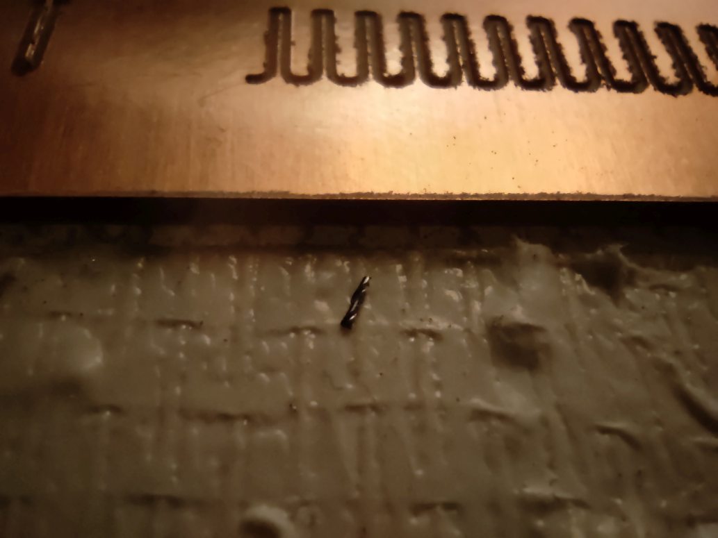
The second try worked better. So we can now reset the Z origin to make the cutting with the 1mm end mill.
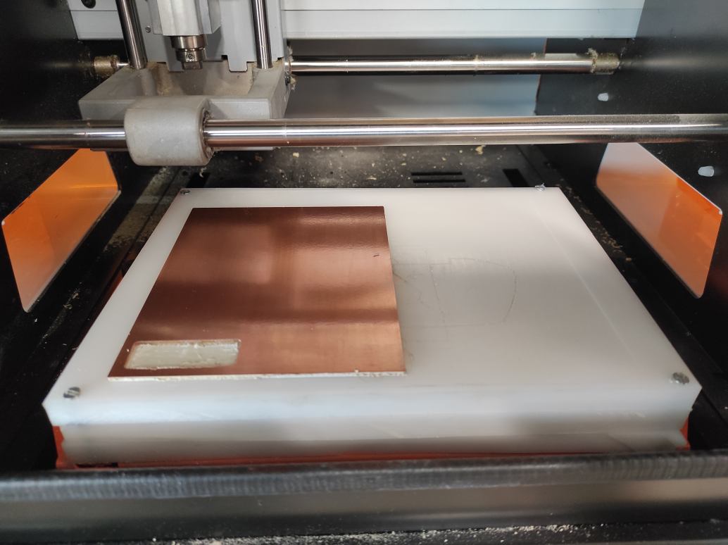
The cutting finished without trouble. A bit of tape gripped around the end mill and need to be cleaned.
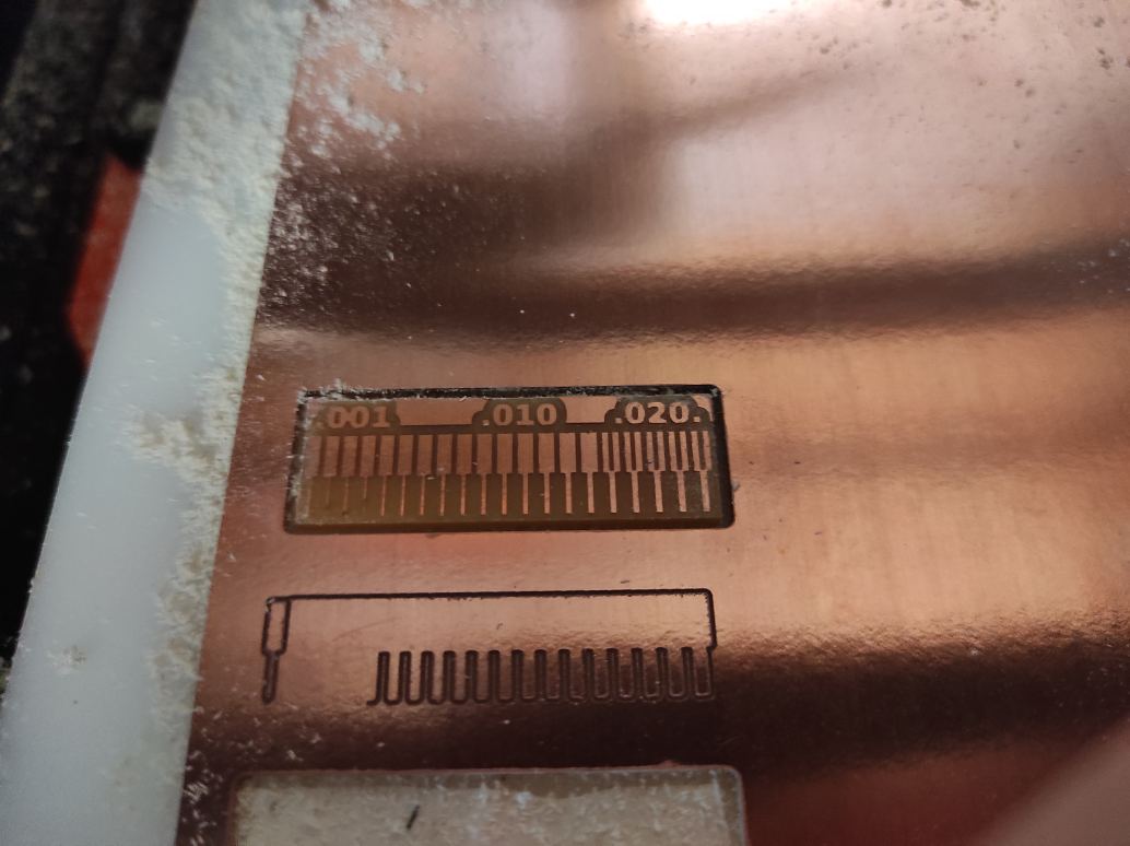
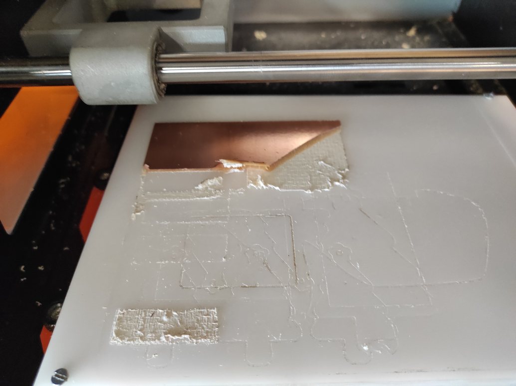
The test need to be took off using a spatula. The Results is quite good with this parameters.
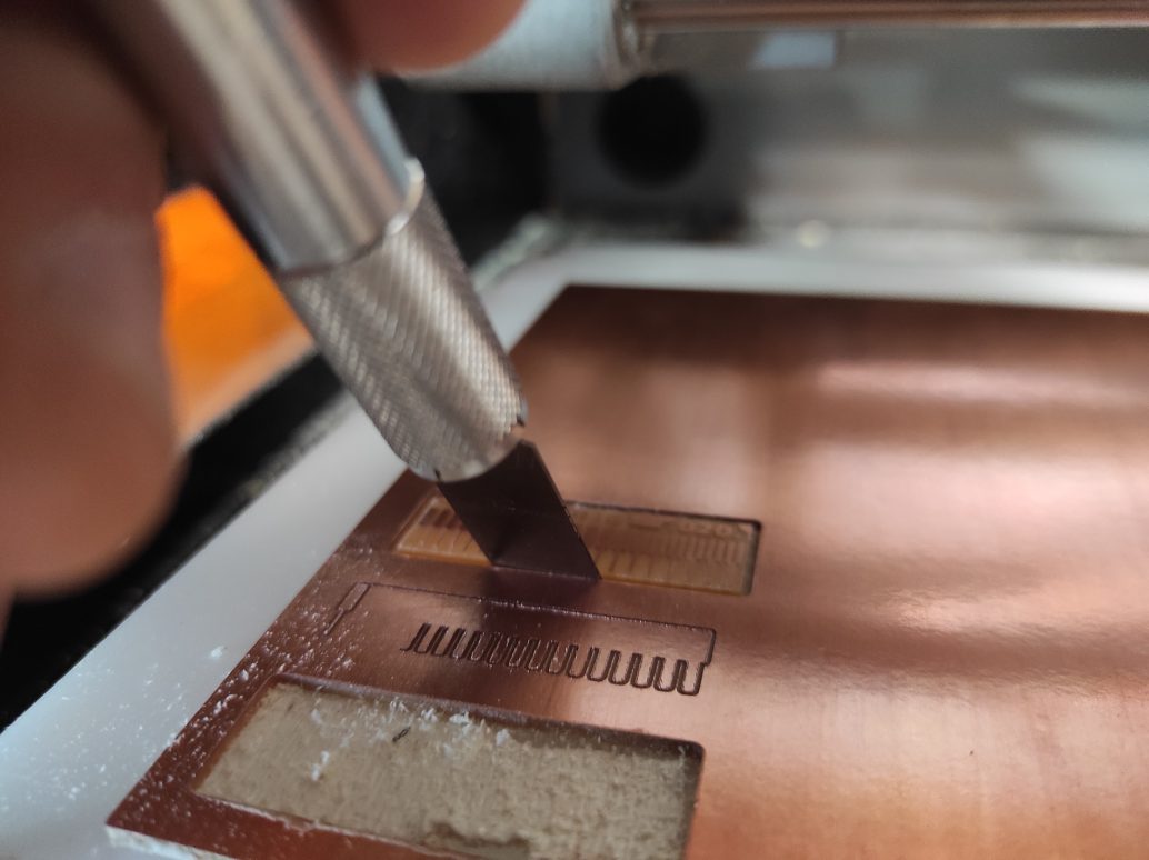

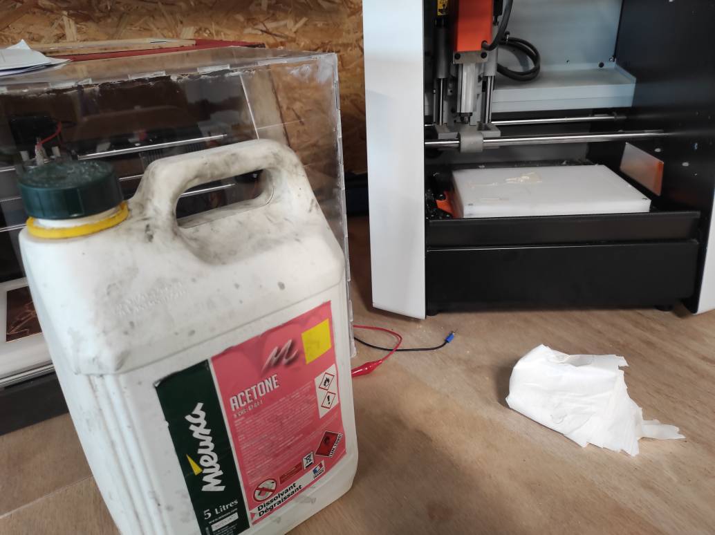
Taking off the rest of the CCL was difficult because of the double-sided tape being too sticky. We have to clean the different parts with acetone.
Different setup
Test V-Bits
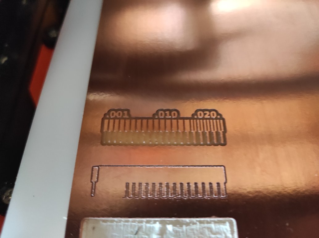
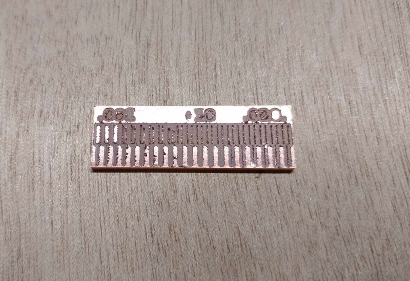
We test the V-bit in the same way as the other cutter. The only changes concern the parameters: we drill to a depth of 0.1 mm min and max, with a 0.1 mm diameter cutter. The offset is 4 and the stepover 0.25 because of the V shape. We also used a speed of 1.5 mm/s.
Here’s the result, which isn’t very convincing:
Test L1S 0.4 SL2.0
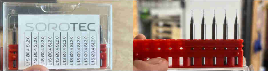
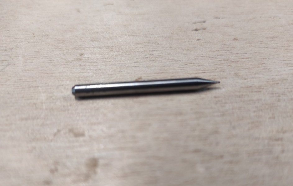
So I was interested in using L1S 0.4 SL2.0 milling cutters, which have the particularity of being single flute, with a diameter of 0.4mm and a length of 2mm. I’m guessing that this model is no longer available because when I went to the website Sorotec, I couldn’t find the model I was using and therefore the technical data sheet. When I first tried it out, I thought it would break during the test because it was so thin and long. I made the traces with this file and chose to use only 1mm/s as the speed parameter to avoid potential breakage. For the other parameters, I used the same values as with the L2SA 0.4mm. For cutting, I used a 1mm L2SA cutter as for the other tests, with the same parameters.
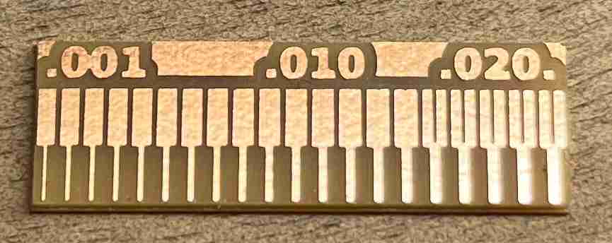
You can find the rml files for Traces and test_interior.rml here. Contrary to what I thought, the milling cutter didn’t break and on the contrary it gave a very satisfactory result. I chose to use it to make my PCB but it broke during the milling process.
Test results
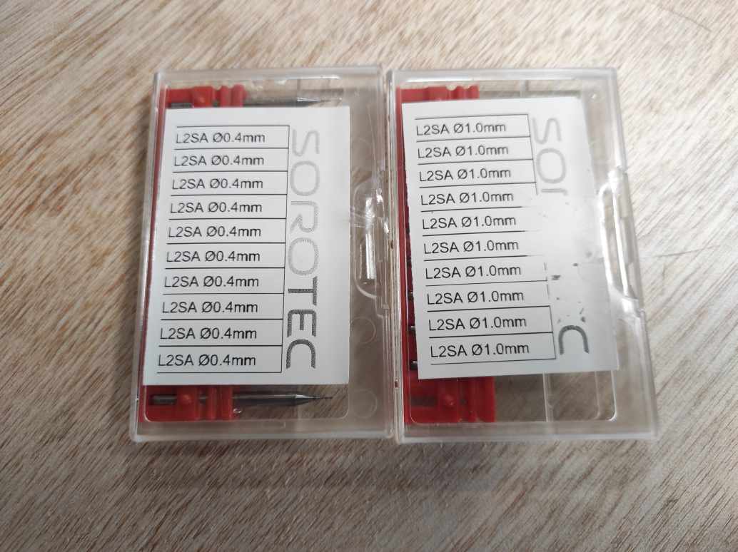
After testing these end mills, we decided to make our own PCB, with the L2SA 0.4 Flat End mill at 1.5 mm/s speed.
Send a PCB to a board house
In order to order a PCB, we first looked at which PCBs we could try to make. After a long period of reflection, we found a trio of boards made a few years earlier by fabacademy instructors.
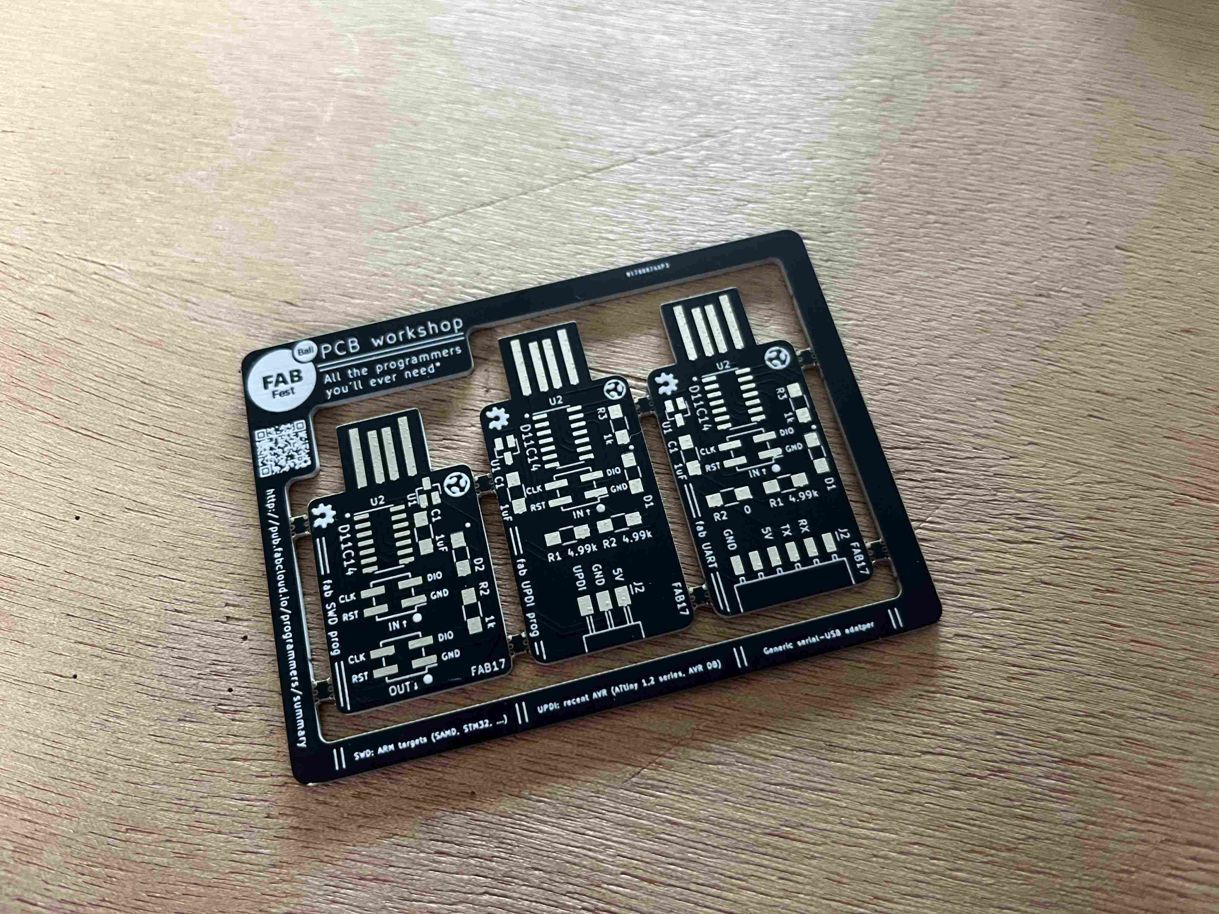
In the end, we were helped by Henk Buursen, a fabacademy instructor in Amsterdam who had been involved in the creation of these boards. Henk was able to direct us to this documentation of the Programmer Serial D11C. This board is a UART programmer for programming 5V BOARDs. We were thus able to download the Gerber file, which you can download here.
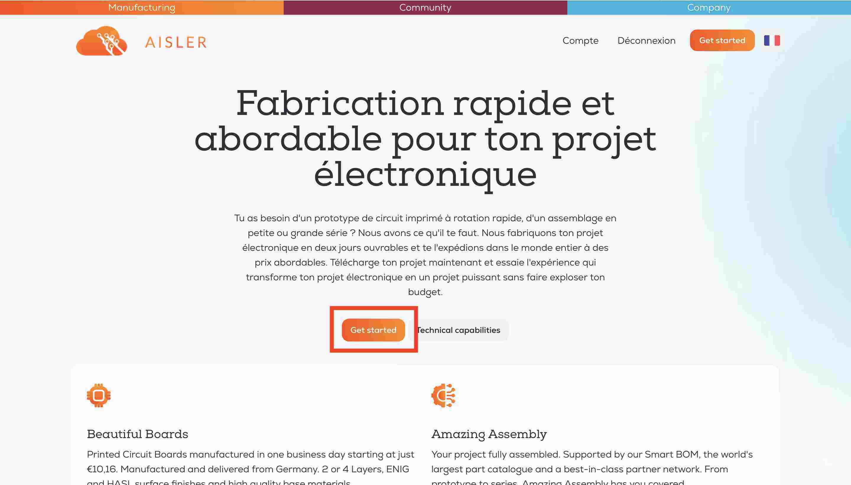
We then had to send the PCB to a manufacturer, and with Luc’s advice we chose to work with Aisler a German manufacturer. All we had to do was follow the steps methodically, the site is easily accessible and fairly simple to navigate. First, we’ll go to the home page and select getting started
We then arrive on a page where we can select our file. There are different methods, for example using a Kicad plug-in to send the information directly from our PCB. .zip
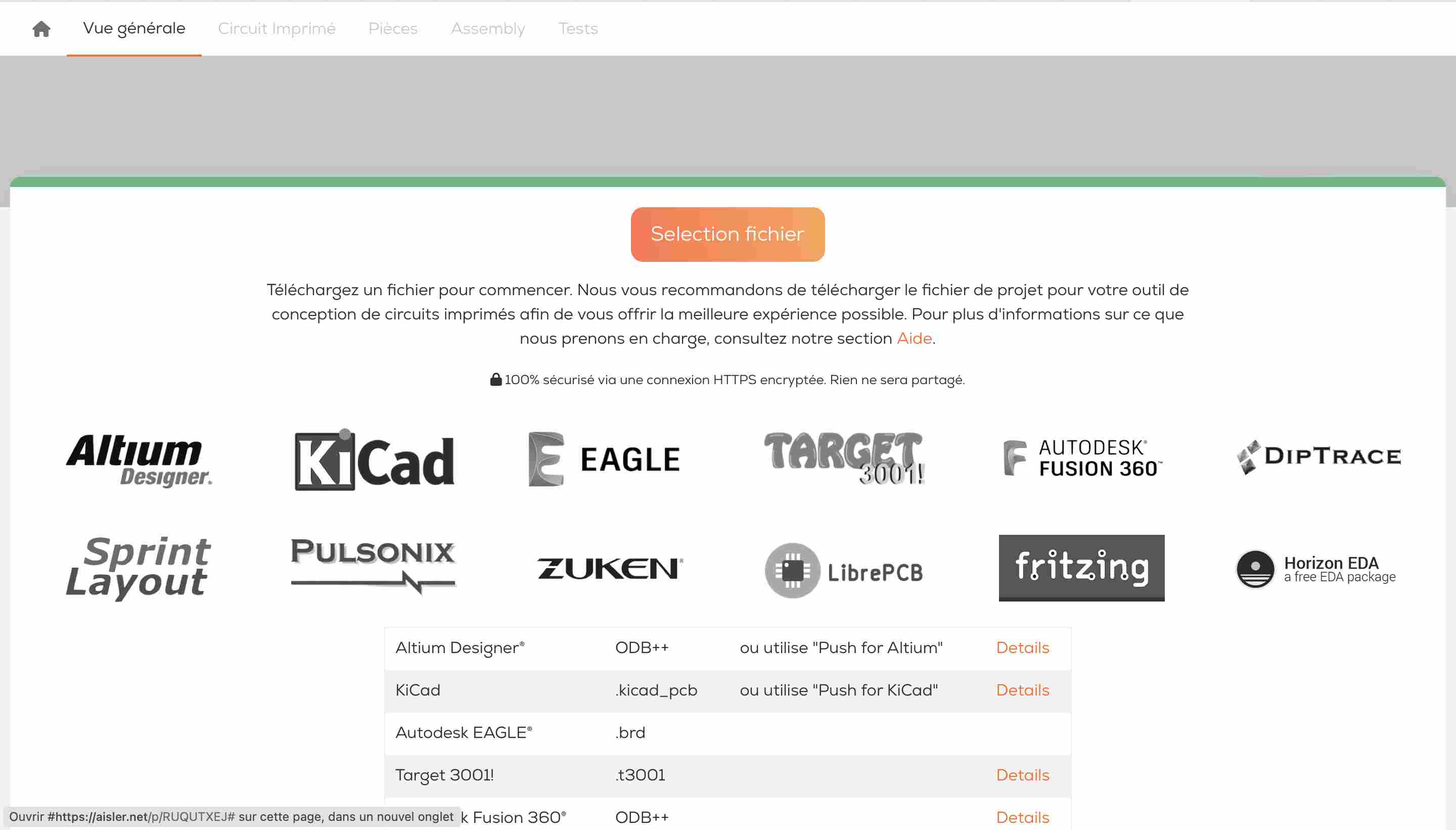
We can then choose (if the result is satisfactory) different parameters for our board. In our case, we’ve chosen the most classic parameters there are.

Once all the parameters have been entered, you can enter a delivery address, a billing address and a payment method.
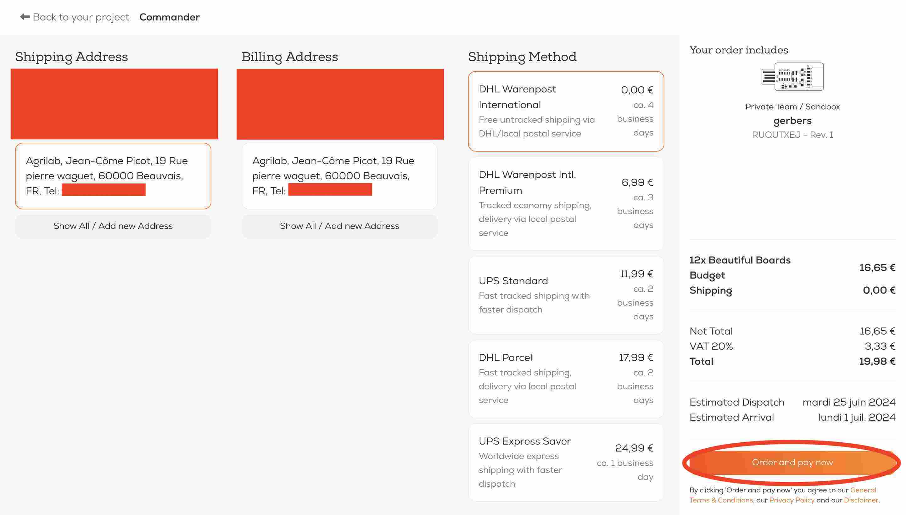
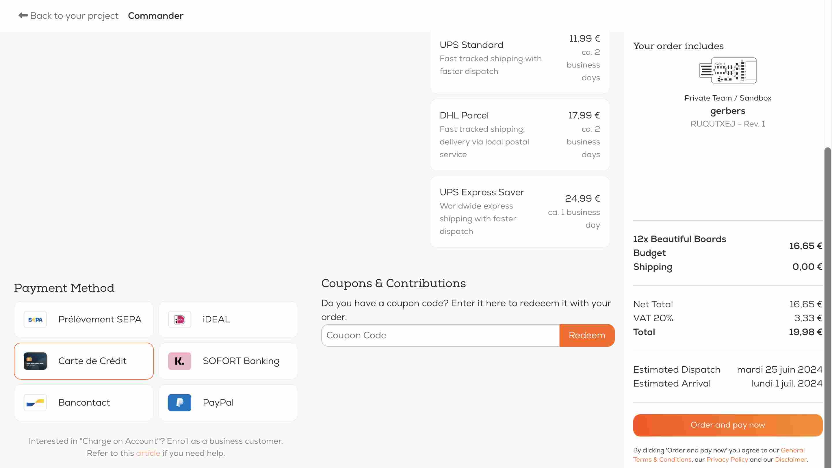
Then all we have to do is proceed to checkout, and once everything is finalized, we receive a message that our order has been taken into account.