Week 03 - Computer controlled cutting
This page serve for documenting our FabAcademy’s group assignement.
For the group assignment, we agreed on tasks to realize and on the design of our models.
Group Assignment :
- characterize your lasercutter’s focus, power, speed, rate, kerf, joint clearance and types
Focus
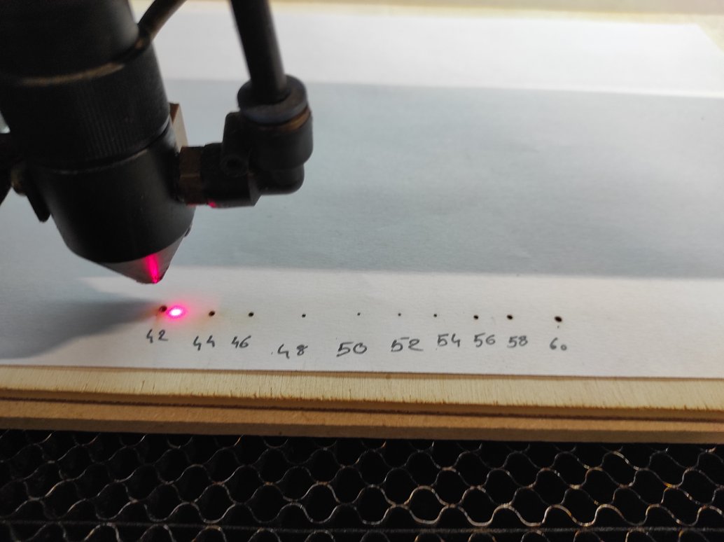
We made the focus alignement, inspired by 2022 Agrilab students work.
We used a caliper to measure distance between a sheet of paper and the down edge of the tightening ring.
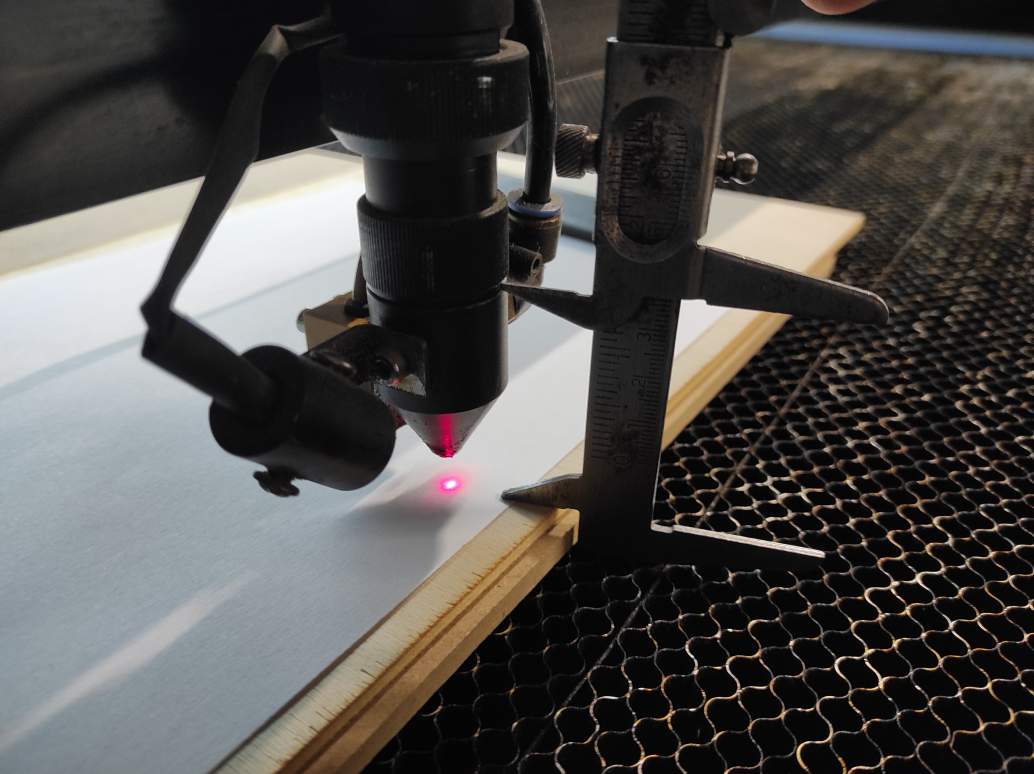
We made a series of point with a z modifier. I found the 50mm settings was the finest point on the paper and correspond to the autofocus setting.
Power/Speed rate
Cutting
We made on Inkscape the lasercutting test, inspired by the different tests available in our Lab.
The machine used lasercut 6.1 software to run. It needs to read files as DXF, occuring a lot of troubles in conversion with more recent file types. Unfortunately, Lasercut couldn’t read my DXF file, and not knowing at this monent how to solve it, Alexis decided to remake it directly with the Lasercut Software.
Lasercut software uses colors to differentiate the line. It realize the cutting in the order they appeared. The power and the speed of cutting or engraving can be set for each color.
The Lasercut Software was hardwork : each parameters change make to 30 seconds to apply, selecting a path don’t enlight the color corresponding making the more than 25 colors to check very difficult, and the 100mm/s speed go unexplicably slower than the 25mm/s.
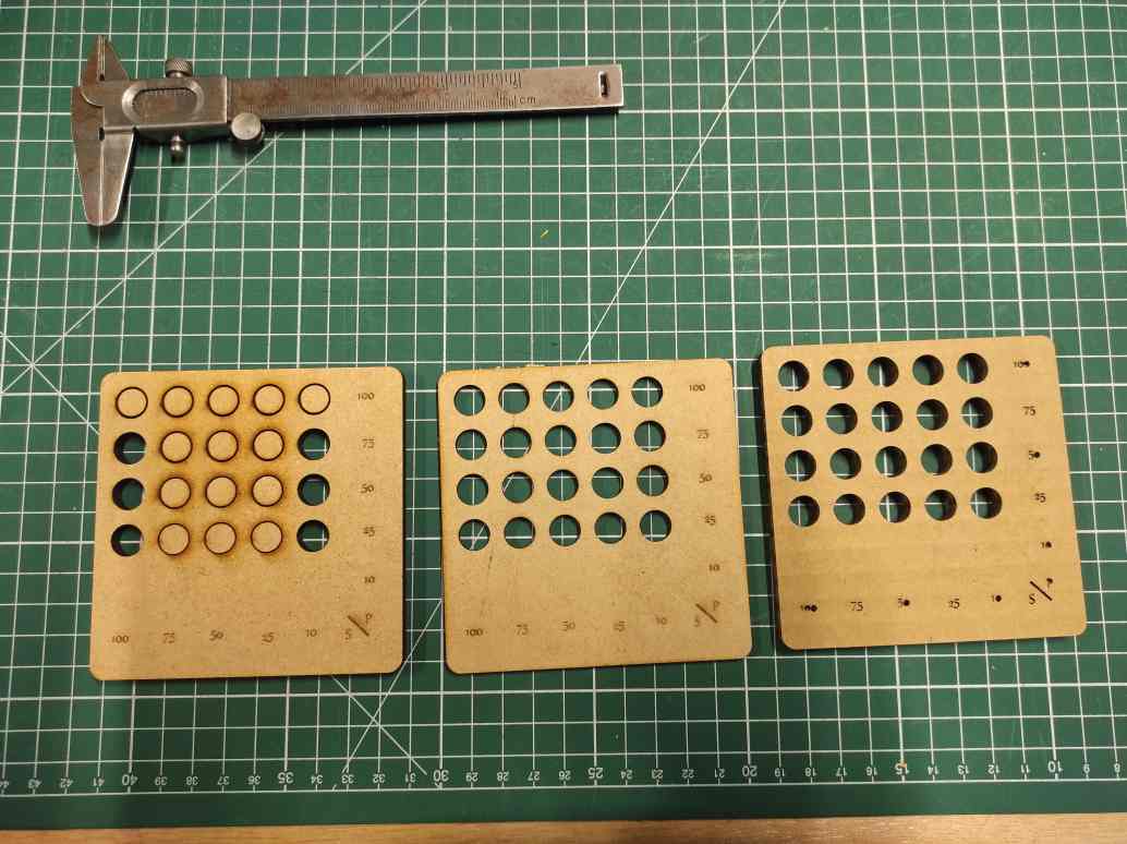
We could make test on 3mm and 6mm MDF and on 6mm cardboard.
Engraving
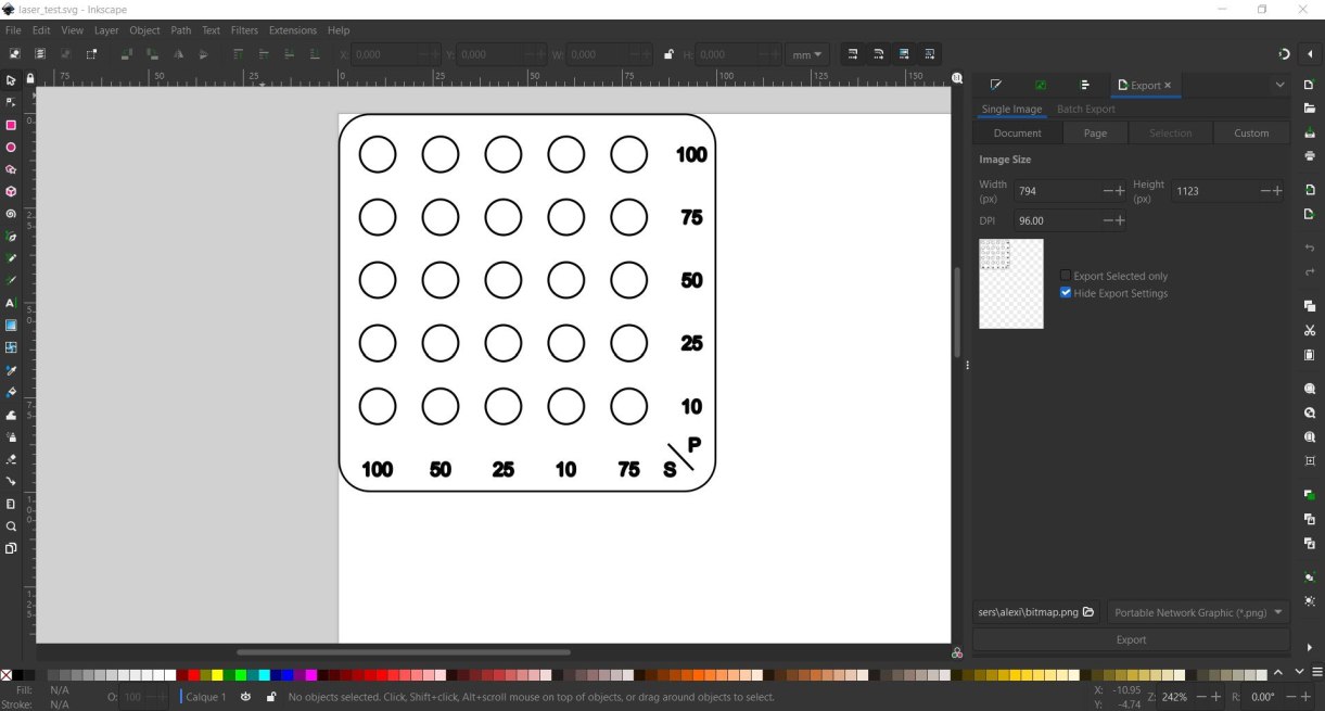
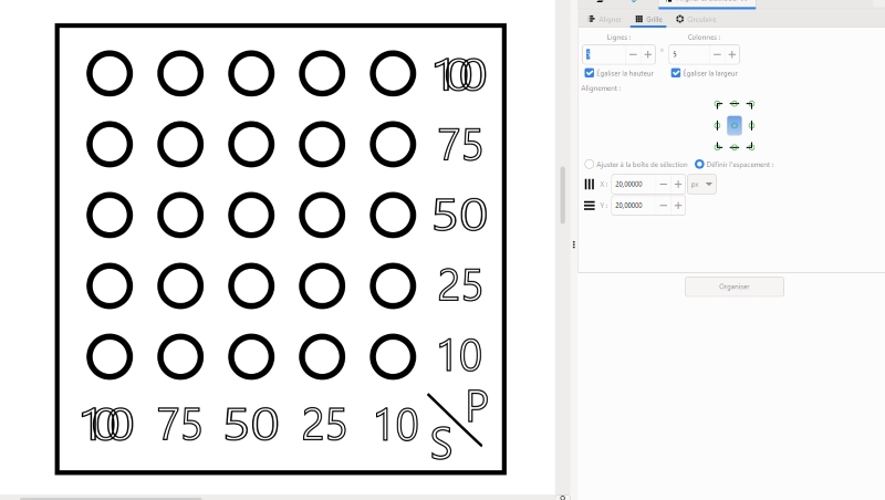
First, we use Inkscape to design our test palette. We make a circle, then copy and paste it 25 times. We select all the circles, go to alignments and distribution, grid, select 5 rows and 5 columns and a 20mm space between the circles. We then add some text, convert it to a vector using the object in the path and export it as a .dxf file.
In the laser software, we need to change the cutting parameters (power and speed) for each circle, and we get this:


Kerf
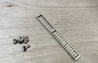
To start off the week, we had some group work to do and now I’m going to tell you how I calculated the kerf and how I played the game. The kerf is the amount of matter destroyed by the laser. It therefore corresponds to the radius at which the laser passed. To determine this value, we had to think about how we could do it. We decided to make as many passes as possible along a certain length and then determine the difference, as this would allow us to repeat the laser pass a large number of times and thus achieve greater precision. The measuring tool we used was a calliper, which is a precision measuring tool. The caliper we used had a maximum length of 12.5cm, so we took care not to exceed 12cm by making a design on fusion 360, with 23 rectangles 5mm wide included in a frame 13cm long.
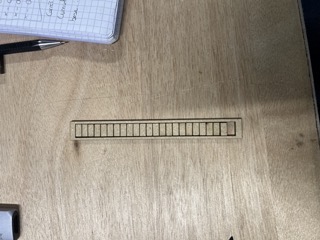
We made an initial cut which didn’t work because the different pieces weren’t cut enough to be separated. Even if we’d broken them, measuring them wouldn’t have been useful because the edges wouldn’t have been glued, so the measurements would have been off. Alexis later realised that we were having this problem because the minimum power setting on the cutter was too low, so we were getting a poor cut when it slowed down at the end of the pass. I still managed to make a good cut by reducing the speed to 20% with 90% power.

You can find the dxf file here
Analysis of results
Once my cutting was complete, I was able to take the measurements for my test. I obtained a measurement of 114.1mm by putting my sections end to end, making sure that they were aligned on each side and that the squares were flat in order to get the most reliable measurement possible. On the frame side, there was a length of 120.2mm that was cut out. So over a distance of 12cm there was a difference of 6.1mm, which corresponded to all the kerfs added together. By dividing, the total difference of 6.1mm for the 24 laser passes that separated them gave us the result of 0.25mm in diameter. This value seems consistent and when Alexis subsequently carried out tests of different bonds, he only subtracted the kerf from the thickness of the material and we had a pretty firm joint.

Joints
Clearance
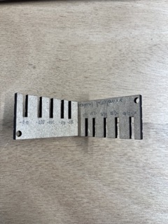
We then turned our attention to joint clearance. This is the clearance between the materials. If the assembly is to fit together correctly, we need to find the right gap so that the materials fit together properly. We therefore modelled a strip on fusion 360 with different slots of different widths to determine the best fit. The material used for these tests was 3mm thick MDF. We created a parameter for the thickness if we wanted to try with another material as well as a tolerance which is the step difference used between the different cut-outs. So in order we had slots of 2.9mm, 2.8mm, 2.75mm, 2.65mm and 2.60mm.

It’s important to note that the kerf hasn’t been removed, so the third slot corresponds to the junction with only the kerf missing. There is still a lot of play. The press-fit is good at 0.4mm, i.e. 0.15mm more than my kerf. In order to estimate where the limit is, I cut another assembly with even lower values to determine the limit for fitting together.
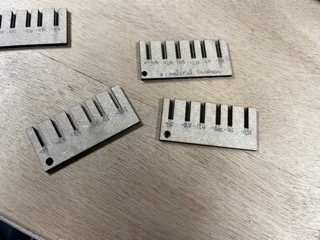
To our great surprise, we didn’t find a limit, even if we went to 0.55mm less than the diameter of my MDF, we still managed to fit them together, even if it required a lot of force. The feeling is that at around 0.15mm less than my kerf, the assembly is sufficiently rigid.
You can find the dxf file here
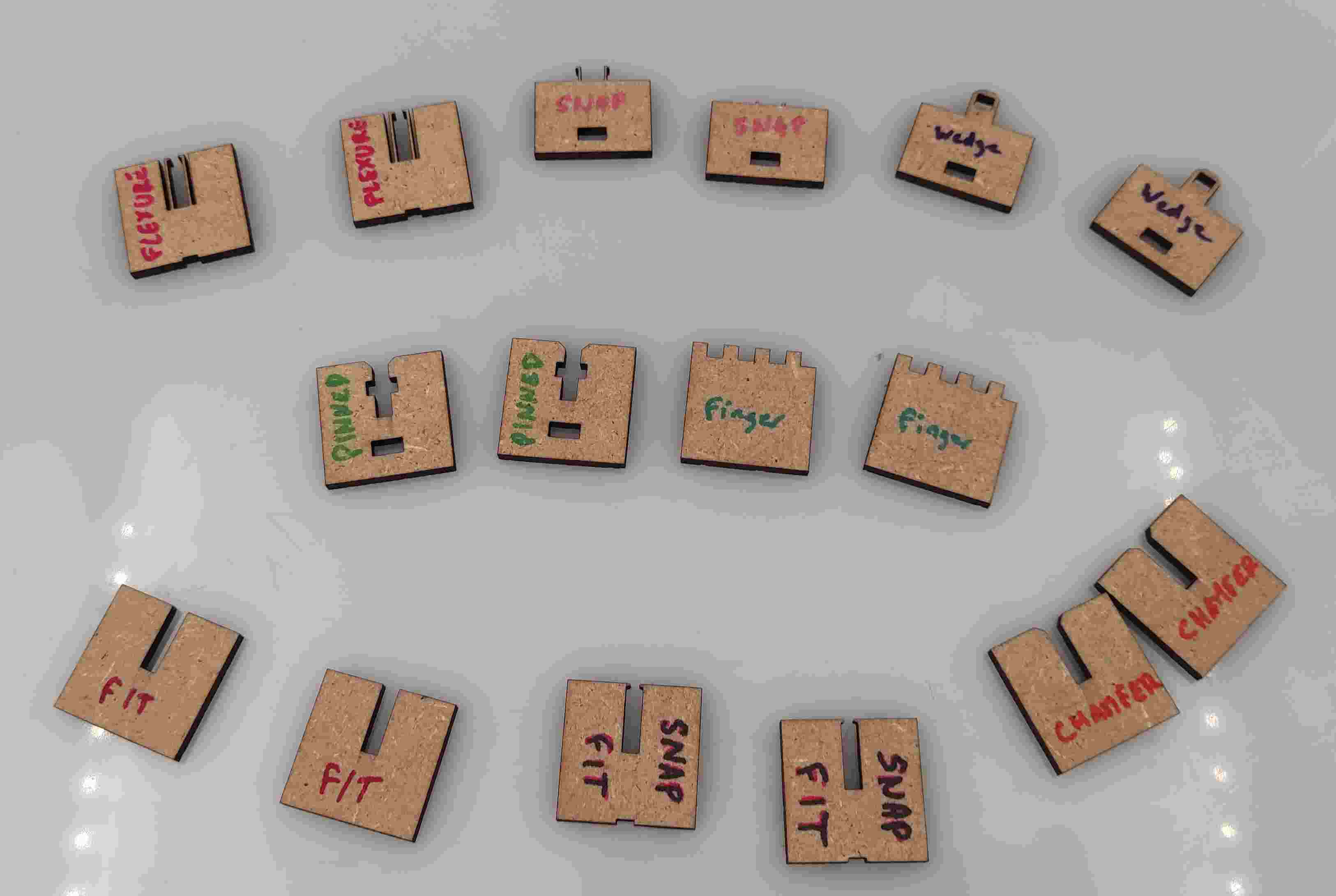
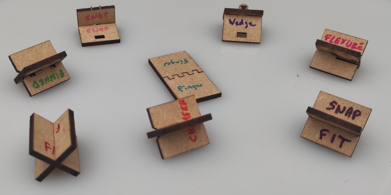
Types
We remade the joints examples provides in the course documenation in fusion. We tried to make it parametric, using fusion paramaters.
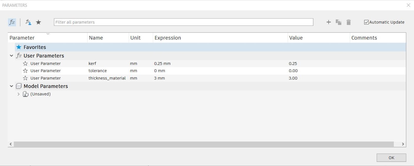
All the models were made in one sketch using formulas as measurement, and constraint to keep them in the right form.
Although, when parameters are changed such as the material thickness, everything couldn’t stay at the right place, probably because some constraints are missing or not pertinent. We need more exploration of that and should certainly make several sketches to facilitate the process and test the parametrics on the go.
To prepare the file for the lasercut, we extruded all the joints, made a new sketch, use the projection tool on all the bodies and add the kerf radius as on offset.