12. Machine Week
Introduction
The world of agriculture needs and uses every day equipment built in steel. At Agrilab we have the capacity to build all these agricultural equipments. The only thing we lacked was a precise and digital cutting of our metal parts. Our manual plasma cutter was able to be controlled from a computer. During the week dedicated to building a machine we decided to build a CNC plasma cutter. Here are the different steps to build the machine
This documentation shows you the different steps to build a CNC plasma cutter. It has been realized in an academic purpose for a team composed of 5 persons. Aurore KUBICA, fabAcademy 2022 student, Luc HANNEUSE, FabManager and AgriLab manager, Théo GAUTIER, FabManager, Jérome RANCON and Celine MARCINIAK AgriLab employee.
This is a collaborative work between each member of the team
Assignment:
Mechanical design

group assignment
   - design a machine that includes mechanism+actuation+automation
   - build the mechanical parts and operate it manually
   - document the group project and your individual contribution

Machine design

group assignment
   - actuate and automate your machine
   - document the group project and your individual contribution
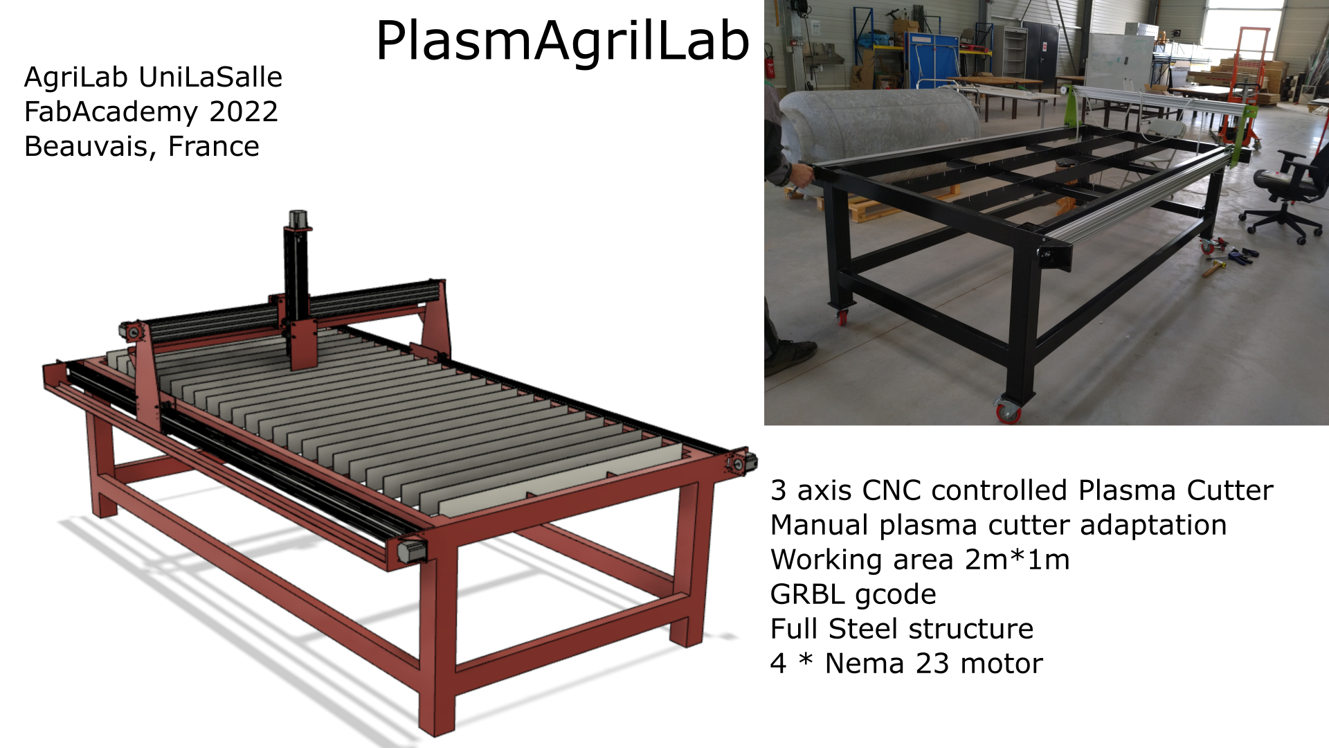
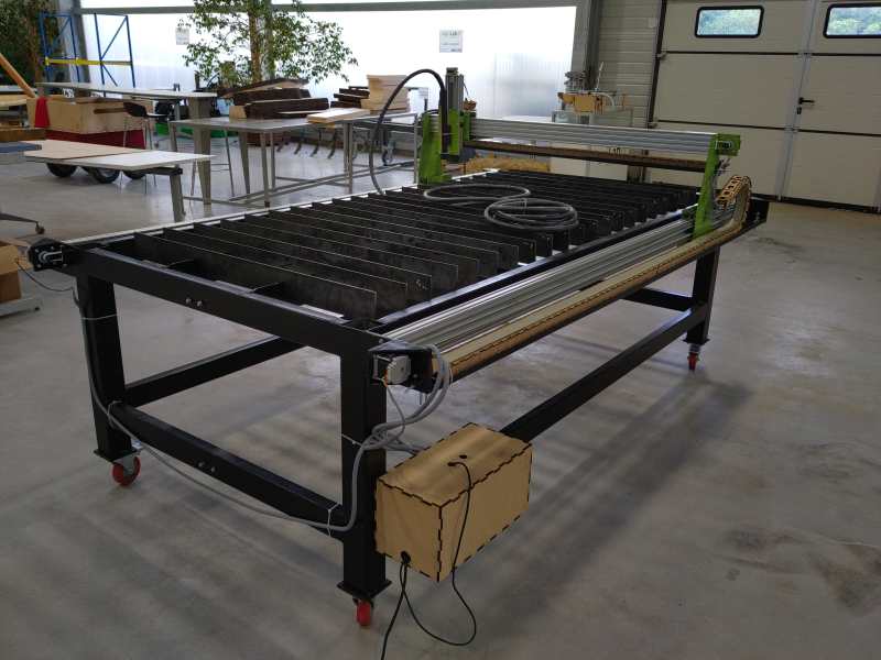
Hero shot
Slide
Video shot
3D plan on Fusion360
Here is the public link to download the file : https://a360.co/3FSQxEi
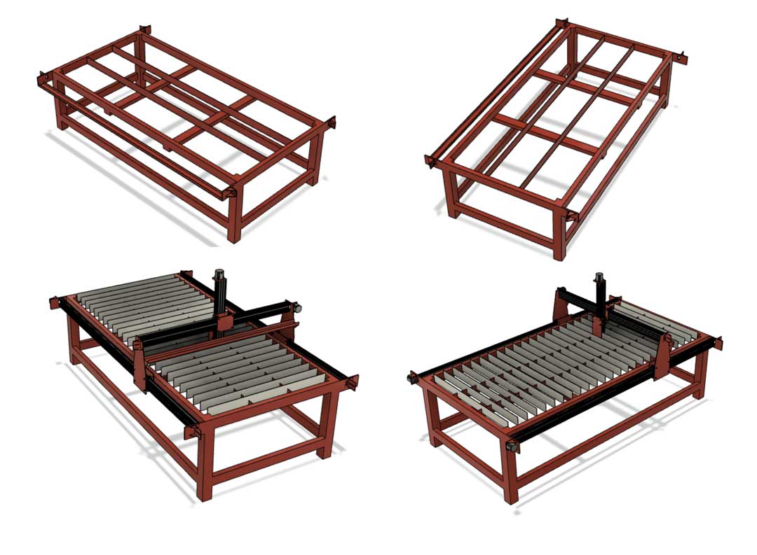
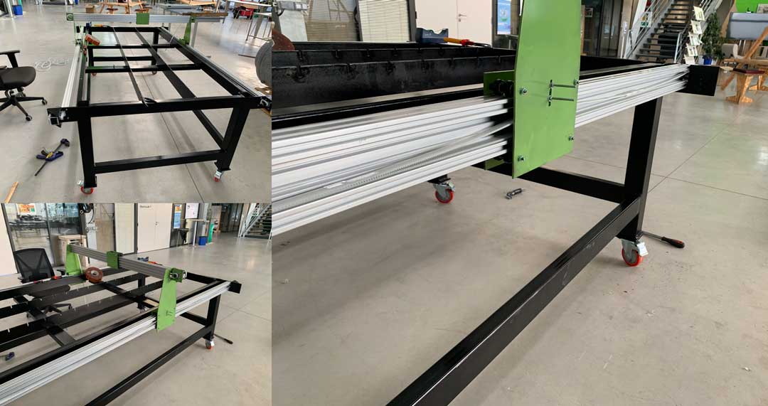
Théo first made a 3D model of the future machine on Fusion360.
After having made an inventory of the stock at AgriLab, he designed a machine. Given the large stock of electronic components and scrap metal we did not have to order a lot of materials to build the machine.
Théo drew each element of the machine separately and then inserted them into an active design.
This makes it easier to separate the elements and to visualize and correct the parts more quickly and easily. An additional interest, it is easier to export a “small” element in DXF format to check the measurements, the nesting, the real size…
As you can see he has drawn the supports for the X, Y and Z axes, he has also drawn the chassis, the sheet metal support, the motor supports and the cable guide supports… Once all these parts were modeled in 3D he inserted them in an assembly file which is called an active design. This allowed him to check if everything was possible and if it would work well.
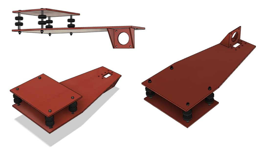
Y support
X support
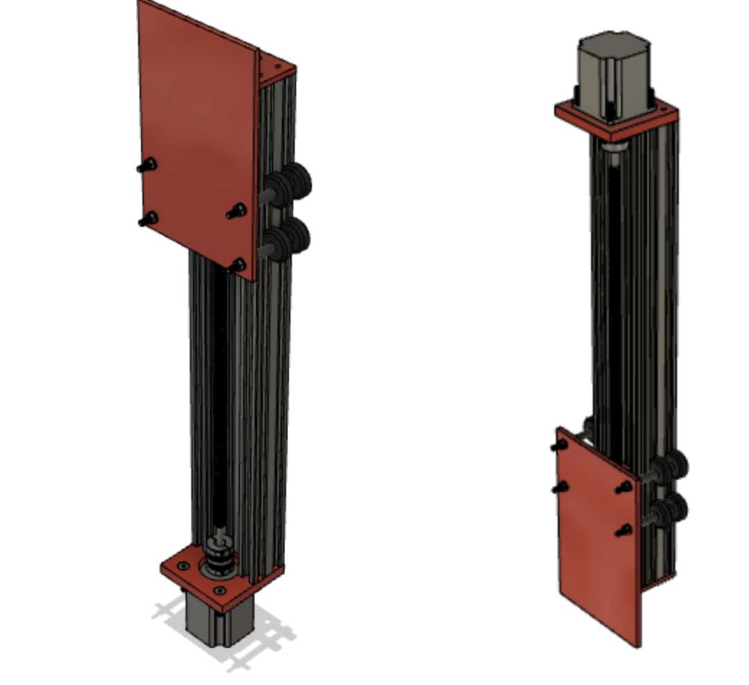
Z axe
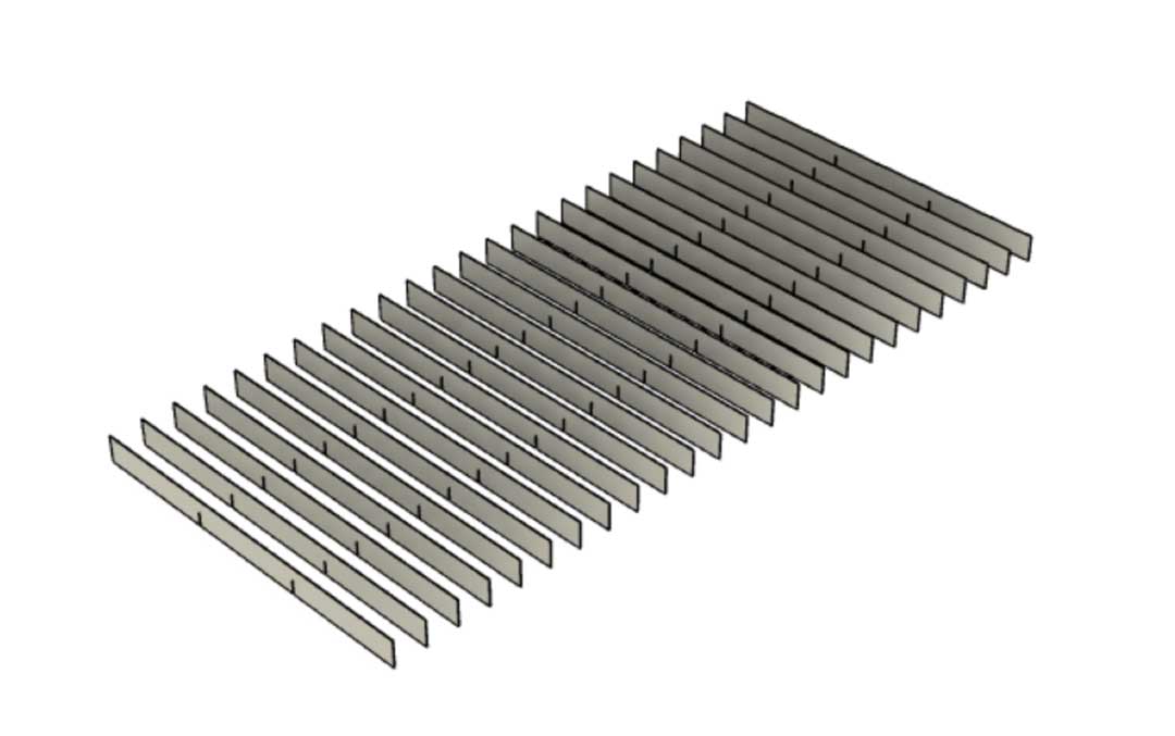
Sacrificial layer
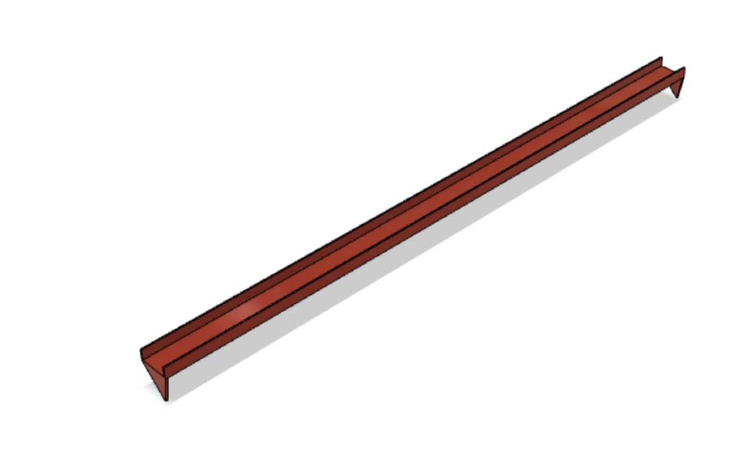
Dragchain support
Final result
Export of the plans and printing
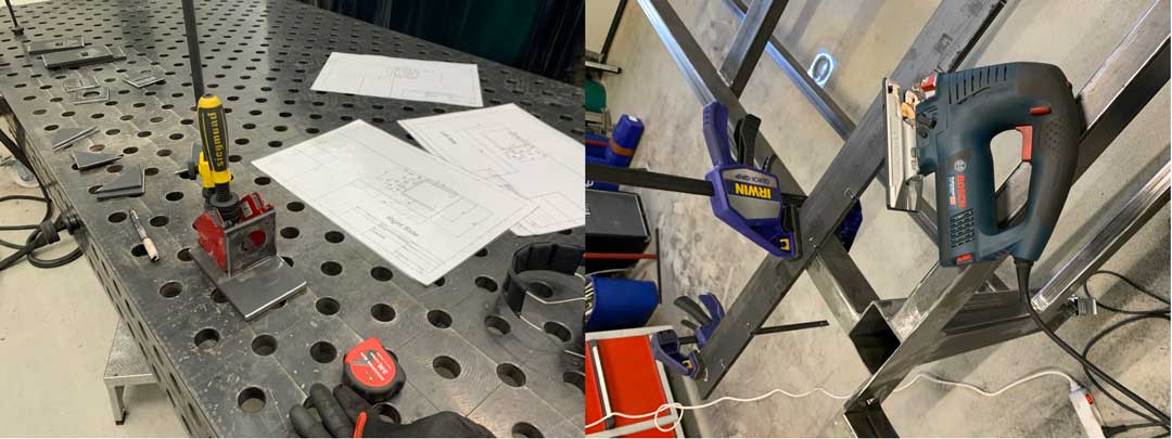
Once the 3D modeling was done, Theo exported the plans in PDF format to start preparing the cutouts of the different metal profiles. For a practical question he plasticized them in order to preserve the quality and their readability of the plans in spite of the work in the metal workshop.
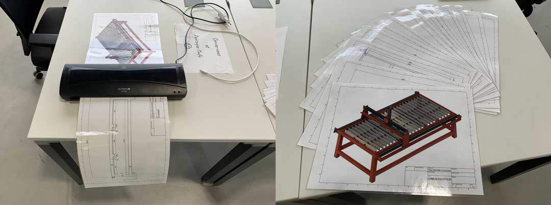
All plans are at the end of the documentation in PDF format
Arduino and GRBL
Parts
| Part | Quantity |
|---|---|
| NEMA 17 step motors | 1 |
| NEMA 23 step motors | 3 |
| CNC GRBL arduino UNO compatible board | 1 |
| HR4988 Motor drivers | 4 |
| Arduino UNO | 1 |
| Connectors for wiring | # |
| Recycled power supply | 1 |
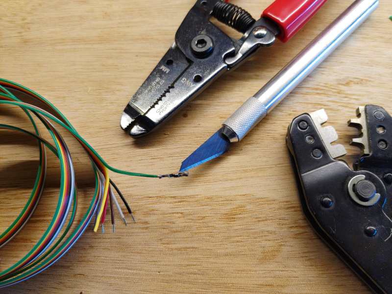
Tools
- GST Crimping Tool
- Soldering iron
- Clippers
- Multimeter
- Cross screw driver
- Wire stripper
Software
GRBL
GRBL is an Open-Source firmware that runs in Atmega328 based Arduinos for low cost CNC machines. The version I’ve used is the v1.1 released in 08/2019.
I’ve dowloaded the repository:
git clone https://github.com/grbl/grbl.git
Compiling and Flashing GRBL using Arduino IDE
- Launch the Arduino IDE
- Make sure you are using the most recent version of the Arduino IDE!
- Load the
grbl folderinto the Arduino IDE as a Library. - Click the
Sketchdrop-down menu, navigate toInclude Libraryand selectAdd .ZIP Library. TheAdd .ZIP Librarycommand supports both a .ZIP file or a folder. In our case, there is no.ZIPfile. - You can confirm that the library has been added. Click the
Sketchdrop-down menu again, navigate toInclude Library, then scroll to the bottom of the list where you should seegrbl. - IMPORTANT: Select the
grblfolder inside thegrbl-XXXfolder, which only contains the source files and an example directory. - If you accidentally select the
.zipfile or the wrong folder, you will need to navigate to your Arduino library, delete the mistake, and re-do Step 3. - Open the
GrblUploadArduino example. - Click the
Filedown-down menu, navigate toExamples->Grbl, and selectGrblUpload. - Do not alter this example in any way! Grbl does not use any Arduino code. Altering this example may cause the Arduino IDE to reference Arduino code and compiling will fail.
- Compile and upload Grbl to your Arduino.
- Connect your Arduino Uno to your computer.
- Make sure your board is set to the Arduino Uno in the
Tool->Boardmenu and the serial port is selected correctly inTool->Serial Port. (There are some controller boards on ebay that have the Arduino Pro bootloader on it, if you get error messages like “avrdude: stk500_getsync() attempt n of 10: not in sync: resp=0x20” then choose another board, try Arudino Pro/Pro Mini) - Click the
Upload, and Grbl should compile and flash to your Arduino! (Flashing with a programmer also works by using theUpload Using Programmermenu command.)
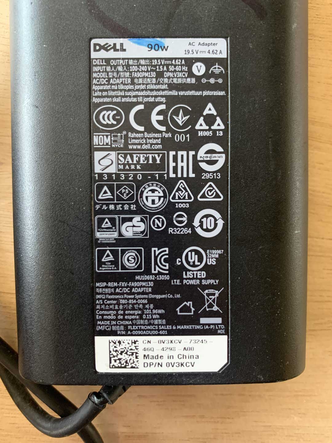
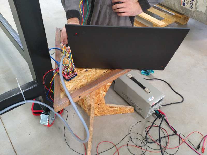
Using an recycled Power supply
We checked possible power sources and the most suitable one was this recycled power supply. So we took an old 90W PC power supply.
In AgriLab there’s a large stock of recycled parts and materials.
| Power Supply DELL | Voltage | Current |
|---|---|---|
| Output | 19,5 Volts | 4.62A |
| Input | 110-240 Volts | 1,5A |
Outputs
This is the table with the Voltage output of the device.
| Part | Voltage | Source |
|---|---|---|
| Arduino UNO board | 5 Volts | Computer |
| GRBL board | 19 Volts | Power suply |
| Plasma cutter | 380 Volts | Three-phase plug |
CNC board
Characteristics:
| GRBL | Board | |
|---|---|---|
| Operation voltage | 12 to 24 V | not regulated, only protected by a fusible |
| Axis | 3 connectors for XYZ | +1 Clone axis connector |
| Limit switches | +-X, +-Y, +- Z | |
| Spindle control | Enable, Direction, cooling | Also used for laser output control |
| Machine override controls | Abort, Hold, Resume | |
| Emergency stop | ||
| Serial communication pinouts | SDA, SCL, TX RX, RST, 3.3V 5V | |
| Microstepping configuration jumpers | 1/2, 1/4, 1/8, 1/16 |
Assembly
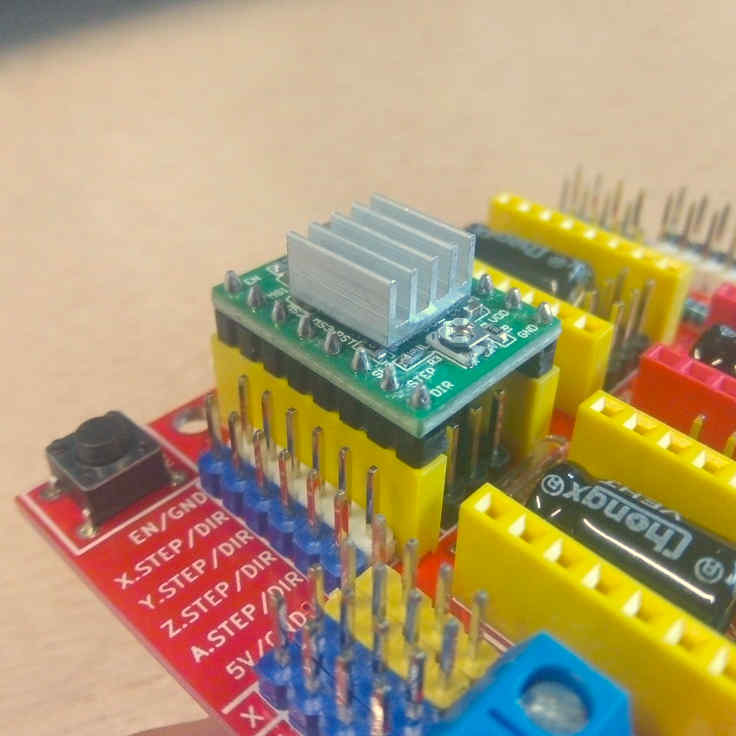
Connect the motor driver boards to the GRBL board sockets. Check the pinout and be sure all the pins coincide correctly.
Motor drivers
Characteristic:
| HR4988 motor driver | ||
|---|---|---|
| Operation voltage | 5 Volts | |
| Resistance | R100 | 0.1 Ohms |
| Motor Voltage Regulator | Potentiometer for VREF |
Pinouts in order:
| Left | Right |
|---|---|
| Direction | GND |
| Step | VDD |
| Sleep | 1B |
| Reset | 1A |
| MS3 | 2A |
| MS2 | 2B |
| MS1 | GND |
| Enable | VMOT |
Setting up the GRBL
Before starting to move its axes it is necessary to take into account the specificities of the machine and to inform the Arduino so that it adapts. For that we followed the steps of benMaker which allowed us to modify the values of our GRBL and thus have a reliable and accurate machine
Firmware configuration
The important points of the firmware configuration are:
- Report in inches, which means you need to disable it to use millimeters.
We obtained this measurements by manually measuring the travel length of each axis.
Firmware configuration table:
| Setting | Value | Description |
|---|---|---|
| $0 | 10 | Step pulse time |
| $1 | 255 | Step idle delay |
| $2 | 0 | Step pulse invert |
| $3 | 0 | Step direction invert |
| $4 | 0 | Invert Step enable pin |
| $5 | 0 | Invert limit pins |
| $6 | 0 | Invert probe pin |
| $10 | 1 | Status report options |
| $11 | 0.010 | Junction deviation |
| $12 | 0.020 | Arc tolerance |
| $13 | 0 | Report in inches |
| $20 | 0 | Soft limits enable |
| $21 | 0 | Hard limits enable |
| $22 | 0 | Homing cycle enable |
| $23 | 0 | Homing direction invert |
| $24 | 25.000 | Homing locate feed rate |
| $25 | 700.000 | Homing search feed rate |
| $26 | 0 | Homing switch de-bouncing delay |
| $27 | 0 | Homing switch pull-off distance |
| $30 | 10000 | Maximum spindle speed |
| $31 | 0 | Minimum spindle speed |
| $32 | 1 | Laser mode enabled |
| $100 | 3.33 | X-axis travel resolution |
| $101 | 3.33 | Y-axis travel resolution |
| $102 | 100 | Z-axis travel resolution |
| $110 | 6000.000 | X-axis maximum rate |
| $111 | 6000.000 | Y-axis maximum rate |
| $112 | 2000.000 | Z-axis maximum rate |
| $120 | 500.000 | X-axis acceleration |
| $121 | 500.000 | Y-axis acceleration |
| $122 | 100.000 | Z-axis acceleration |
| $130 | 1200.000 | X-axis maximum travel |
| $131 | 2200.000 | Y-axis maximum travel |
| $132 | 0.000 | Z-axis maximum travel |
VREF calibration
This is an important task to prevent over-heating of the motor drivers, and excessive vibration and over-heating of the step motors.
This the motor datasheet provided by the manufacturer SMD resistor calculator
Calculation:
| Values | ||
|---|---|---|
| Current Sense resistance | 0.01 Ohms | Rsense |
| Rated motor current | 1.3 A | RMC |
| Safety margin percentage | 25 % | SM |
I’ve found this formula VREF = RMC x 8 x Rsense
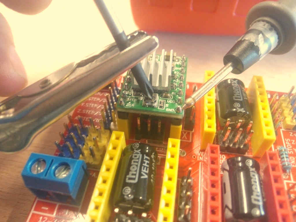
Process:
- Use the multimeter as voltmeter in a scale of less than 5 Volts.
- Get a multimeter with a clamp connector in the cathode
- Power on the GRBL board
- Place the cathode (screw driver) in the VREF potentiometer and the ground probe in the bottom left GND pin.
- Turn the potentiometer clockwise to increase and anti-clockwise to decrease the VREF.
Steps per millimeter for belt driven systems
I’ve calculated this using this calulator.
| Data | Value |
|---|---|
| Motor step angle | 1.8° |
| Driven Microstepping | Full step |
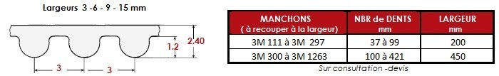
| Belt pitch | 3 mm |
| Pulley tooth count | 20 |
Result: 3.33
| Resolution | Teeth | Step angle | Stepping | Belt |
|---|---|---|---|---|
| 200 micron | 20 | 1.8° | Full step | 3mm |
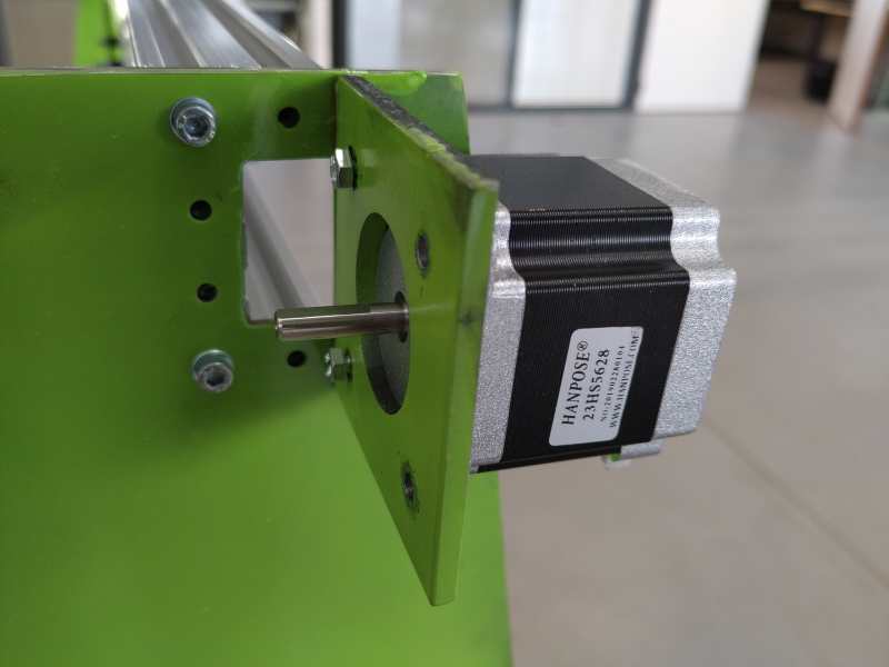
Stepper motor
A stepper motor can spin precisly regarding the degrees also called steps we chose thanks to coils inside the motor. It can also hold a position but you have to power it all the time. To control a stepper motor you need to tell it :
- the number of steps
- the direction
- the speed
For example, you can find it on the 3D printer to move the axis :
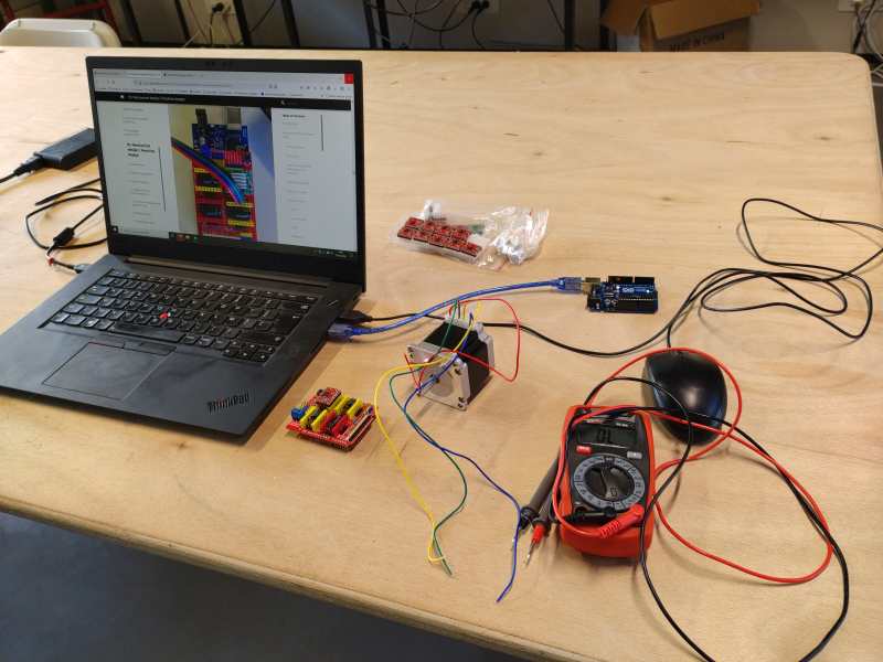
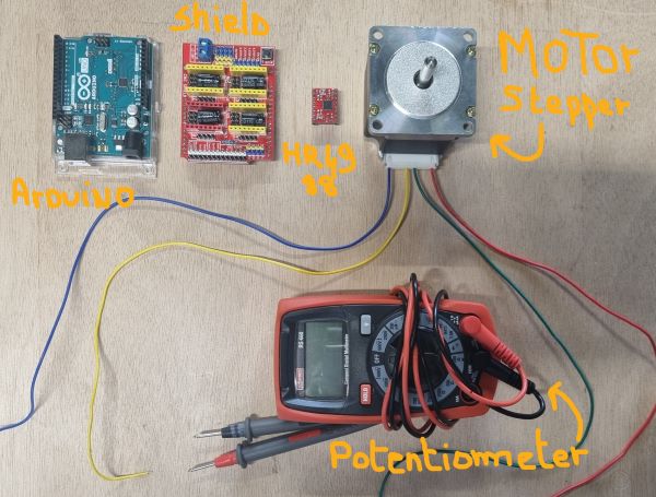
Stepper motor Arduino tutorial
You need :
- 1 x Arduino UNO Board
- 1 x Stepper motor
- 1 x HR4988 Motor driver
- 1 x shield
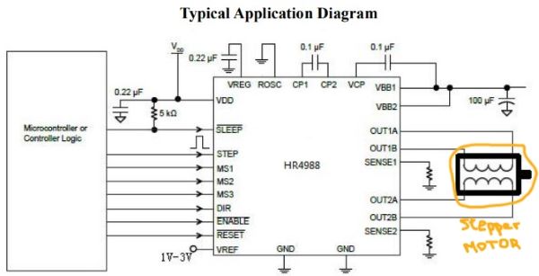
Check the HR4988 Datasheet
Application Diagram
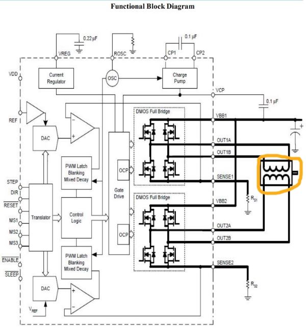
Functional Block Diagram
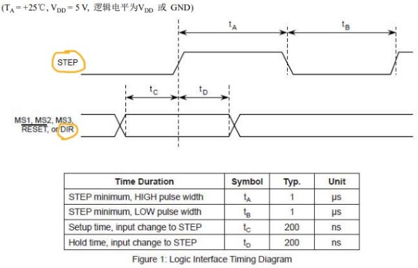
Step and Dir representation
Pin schematic
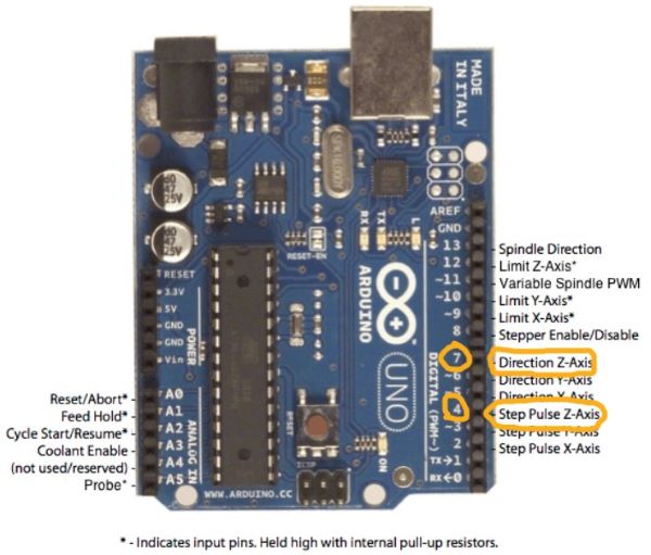
Regarding these informations, I put the motor driver on the Z axis and so the dir pin is the 7 and the step pin is the 4.
Check the power continuity of your wires on the stepper motor
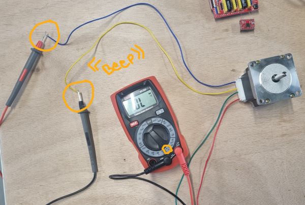
Make your circuit :
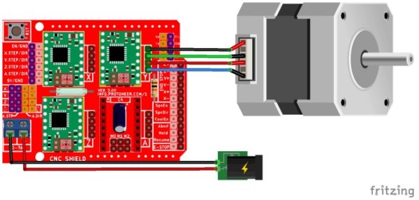
Code it !
// move a stepper motor in one direction and another
int motorpin = 4;  // stepper motor on the pin 4
int dir = 7;

void setup() {
  pinMode(4,OUTPUT);
  pinMode(7,OUTPUT);
}

void loop() {
  for (int i = 0; i <= 200; i++) {
    digitalWrite(motorpin, HIGH);
    digitalWrite(dir, HIGH);
    delay(10);
    digitalWrite(motorpin, LOW);
    digitalWrite(dir, HIGH);
    delay(10);
  }
  for (int i = 0; i <= 200; i++) {
    digitalWrite(motorpin, HIGH);
    digitalWrite(dir, LOW);
    delay(10);
    digitalWrite(motorpin, LOW);
    digitalWrite(dir, LOW);
    delay(10);
  }
}
Flash it and it should work !
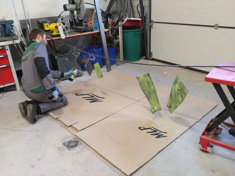
Metal cutting
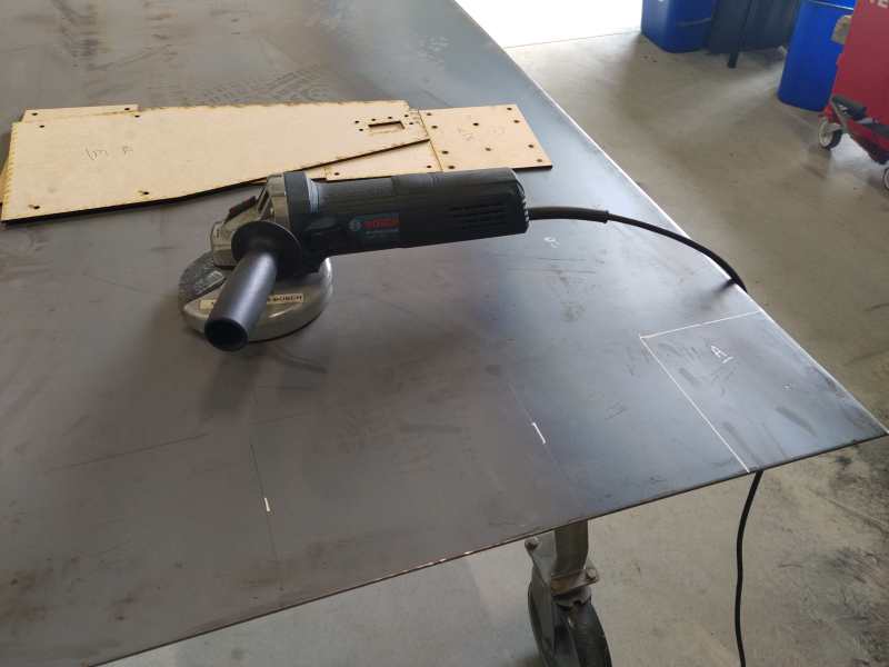
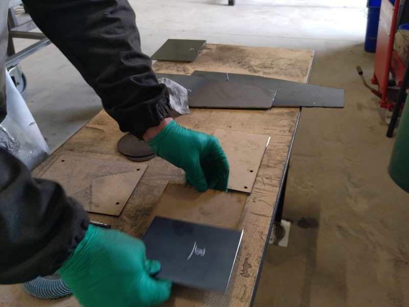
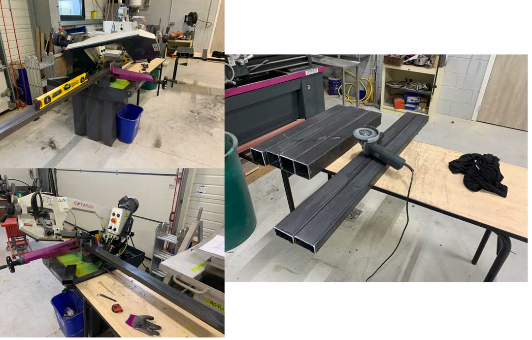
Once all the plans were exported and printed, we could move on to the design. For that Théo and Jérôme cut the different metal profiles with the band saw. Once the tubes were cut to the right size, they used a grinder to sand the sharp edges and prepare the parts for welding.
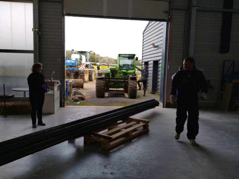
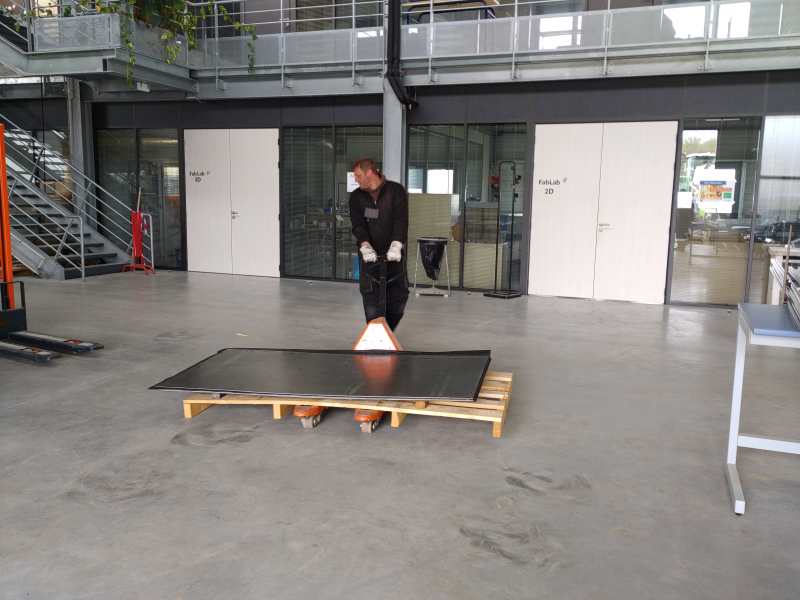
We received the metal in a raw form : 6M long profile and 2 * 1m metal plate.
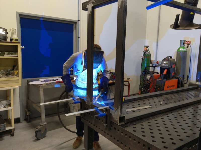
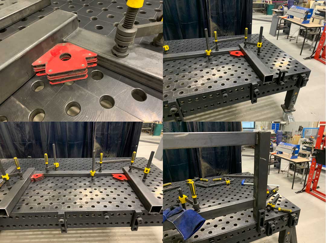
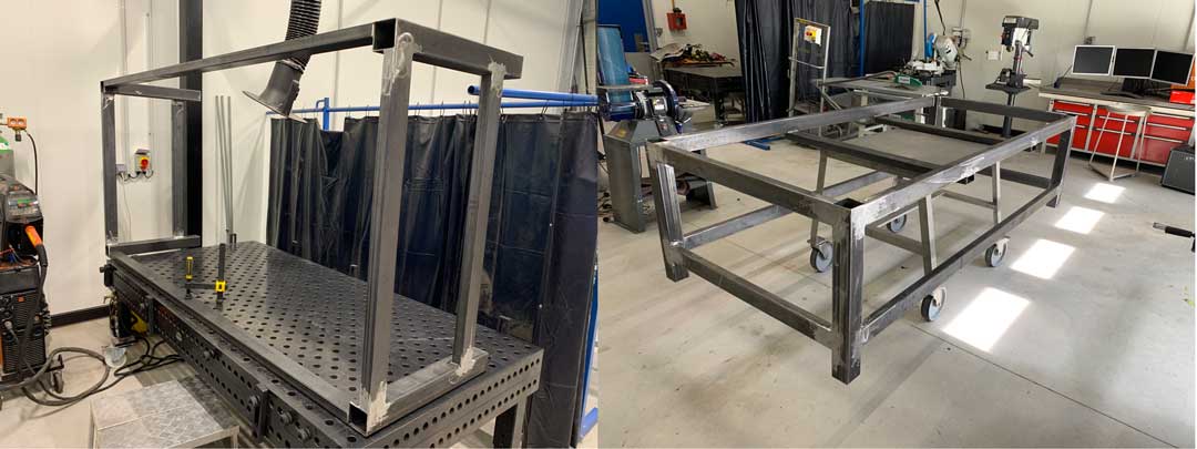
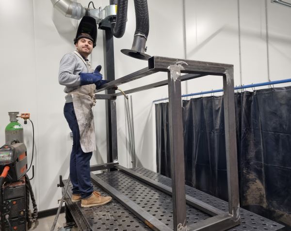
Welding
Theo took care of welding all the elements together, checking the alignment of the tubes. Welding creates a lot of heat and therefore deformation of the metal tubes, so it is very important to check regularly the good linearity of the welded elements. If this is not the case, do not hesitate to use a hammer to straighten the part. All the welds were made with a Kempi MIG machine.
Processing :
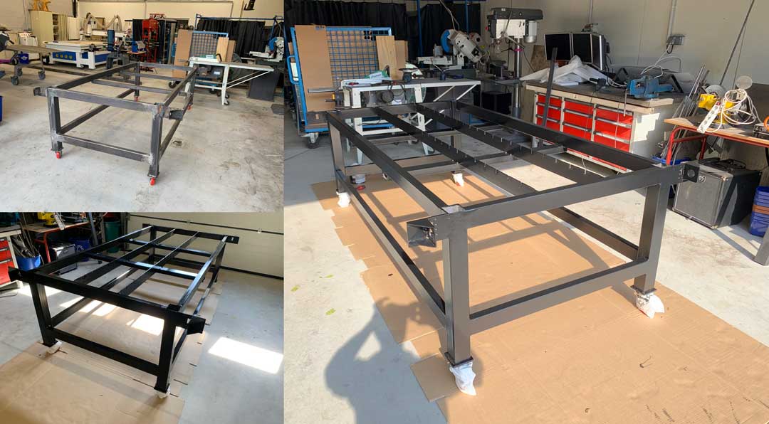
Painting
Once the frame is finished to be assembled Aurore and Théo degreased it and then painted it with a brush and a roller. They chose the color black and green to remind the colors of AgriLab.
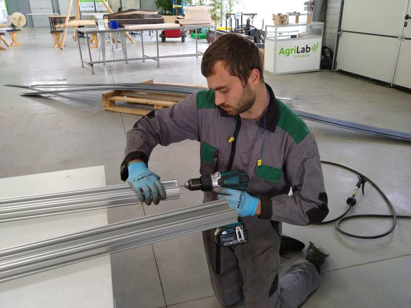
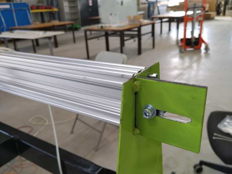
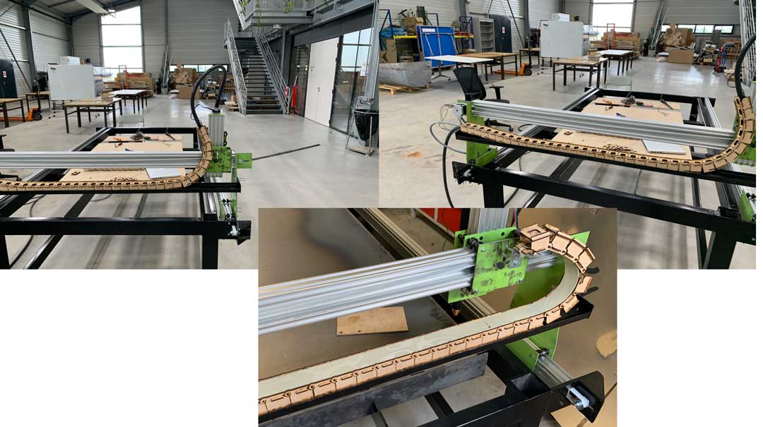
Assembly of the aluminium profile
After a few days of drying of the frame Theo took care of the assembly of the V-slot aluminum profiles. The advantage of these profiles is that many accessories are available and easily mountable on the tubes. Moreover the bearings to drive the different supports of the X, Y and Z axes are bearings designed for this type of profile. They are widely used in 3D printing and bring a lot of precision in the guidance.
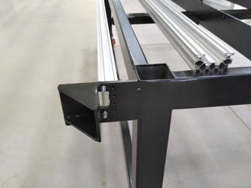
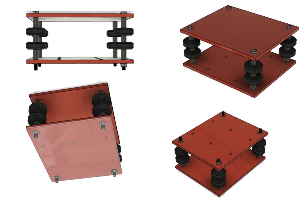
Mounting support and bearing
Once the rails were installed on the chassis we were able to assemble the different supports with the bearings.
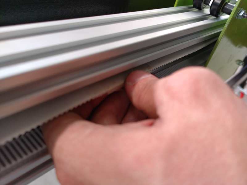
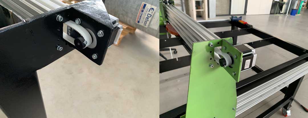
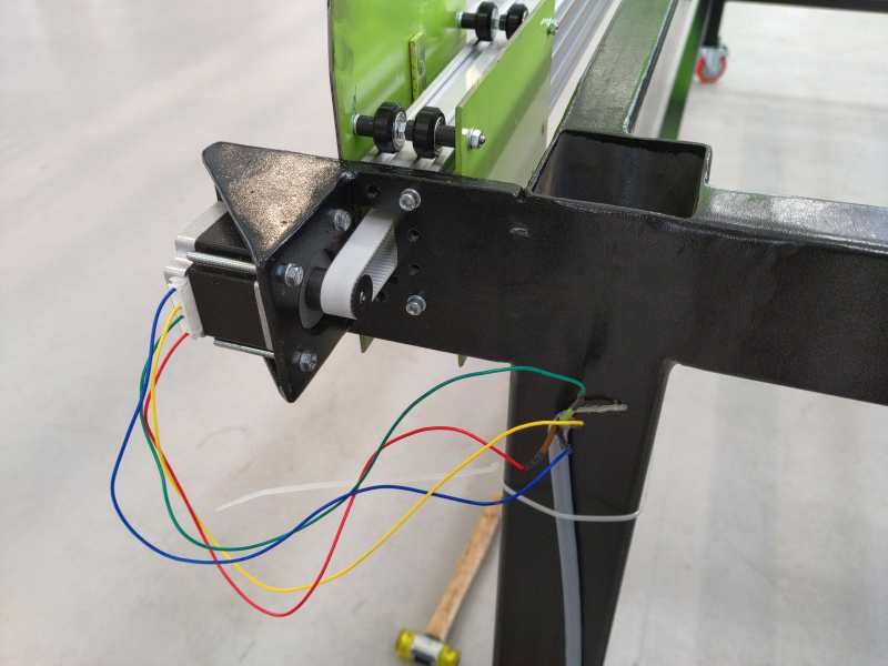
Assembly of the belts and tensions
Then we mounted the Nema 23 motors and the belts to transmit the power.
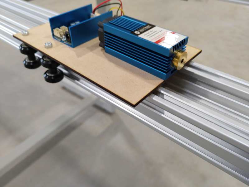
Z axis
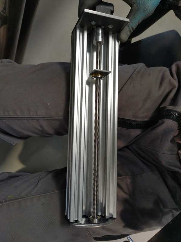
Luc modelized another Z axis for a diode laser. Because we had huge delay to received the plasma end component .
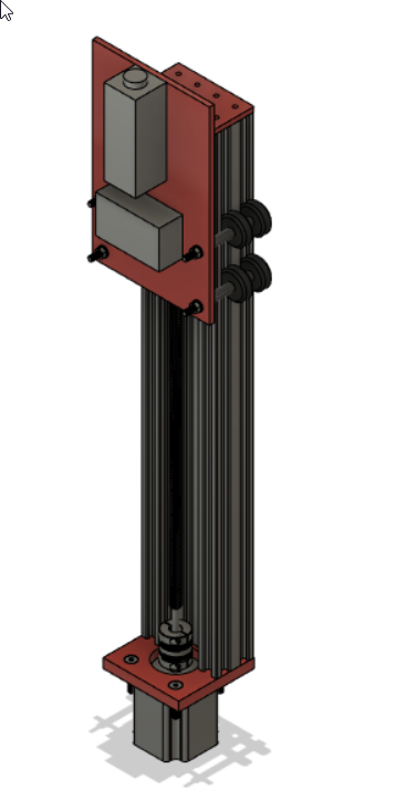
This was temporary built and then replaced by another component.
3D printing of the transmission pulleys
Because we had problems with the parts we ordered, we had to find a solution to transmit the power of our motors to the axes. Luc found an example of a 3D printable pulley that he adapted to fit our needs.
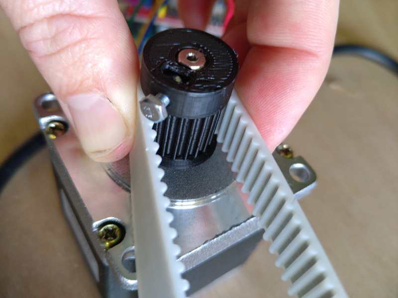
To realize the tension of the belts we realized this operation “with the eye and with the touch”, it is not useful to tighten the belts too much,
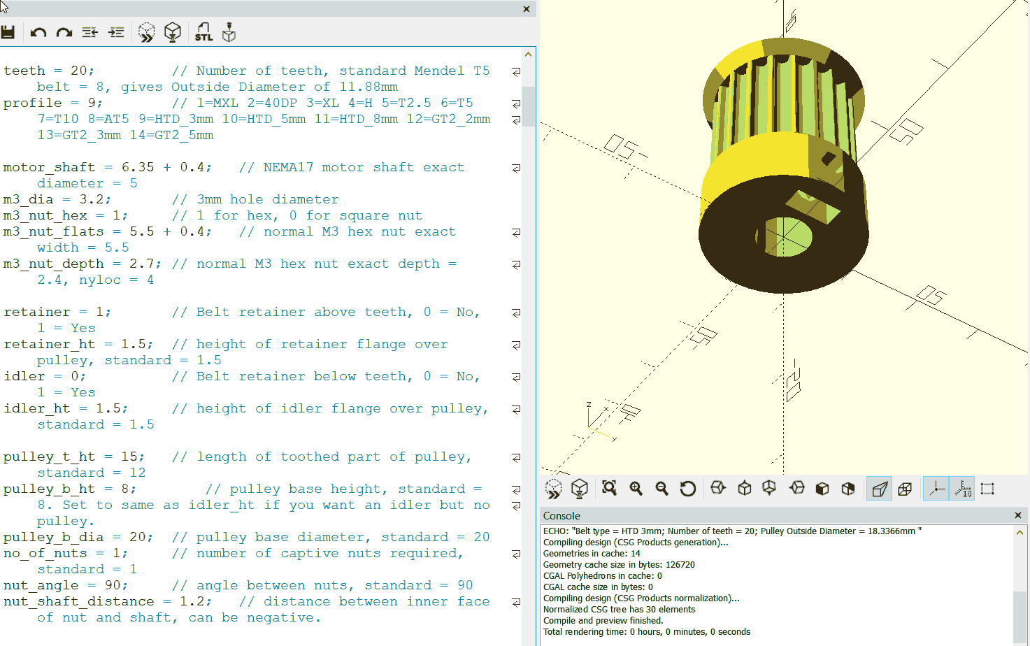
Luc used an OpenScad model from droftarts on thingiverse and modified some parameters for this specific pulley.
OpenScad modified code file Pulley_T-MXL-XL-HTD-GT2_N-tooth.scad .
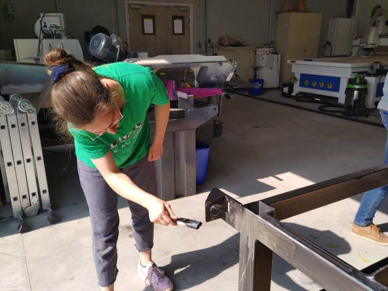
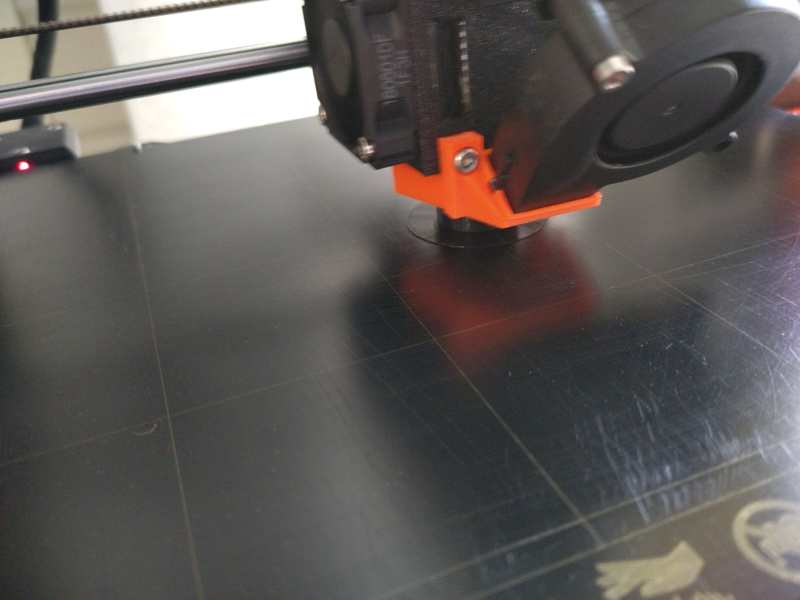
Realization test with pen
Once the setting of GRBL realized we wanted to see if our machine was accurate on these axes. For that we fixed a marker with collars on our Z. We then launched our favorite file.
Remark: the pen not being very well fixed the few visible vibrations are due that the marker move in the displacements. Moreover it goes up as the file advances, hence the fact that some details are missing.
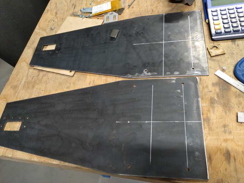
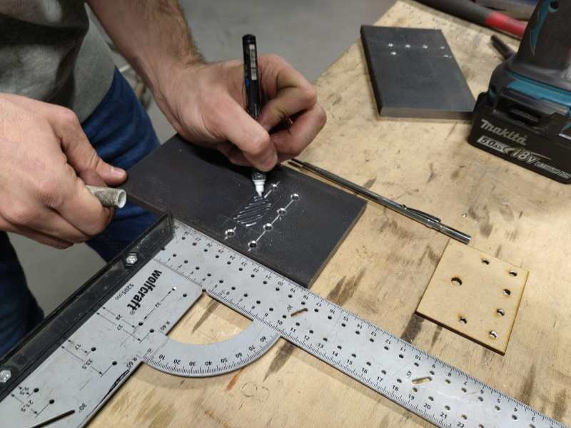
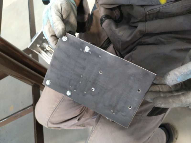
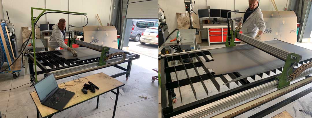
Realization of the plate
For the plate, Theo cut several pieces of metal of one meter length in bars of 80mm of width and 5mm of thickness. Then he cut notches to fit them into the frame. For that he used the drill and a 5mm drill bit and a disc machine to cut the notches. After having all the notches on all the bars he installed them one by one on the frame. With a ruler and a spirit level he leveled the whole deck. For this he took the lowest part of the deck and aligned the other pieces to the reference one.
Integration of the wires
To integrate, hide and protect all the wires and the Arduino we made a box in MDF with laser or we added openings to make air currents and thus cool the environment. For this we used the makercase software and then modified on Fusion360.
We used shielded wire. There are potential high interferences generated by the plasma .
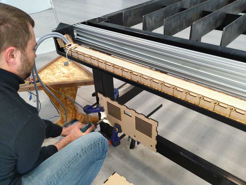
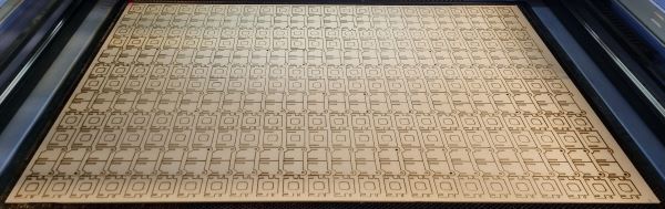
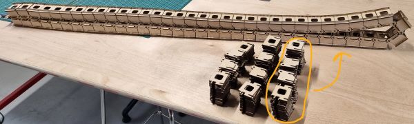
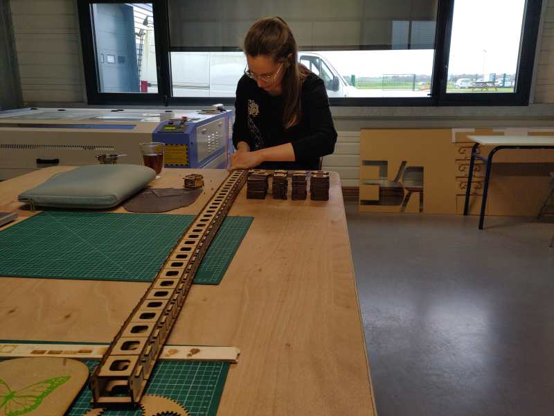
Wooden dragchain realization
To make all the cables of the machine follow, protect them and guide them safely we decided to place them in a dragchain. In order to reduce the manufacturing costs, Theo made a file where all the elements are laser cut in 3mm thick MDF. Then each element is nested one in the other. To give less lateral flexibility we added polypropylene strips of one millimeter thick that are inserted in force in the elements. This allowed us to have a stronger and less flexible chain.
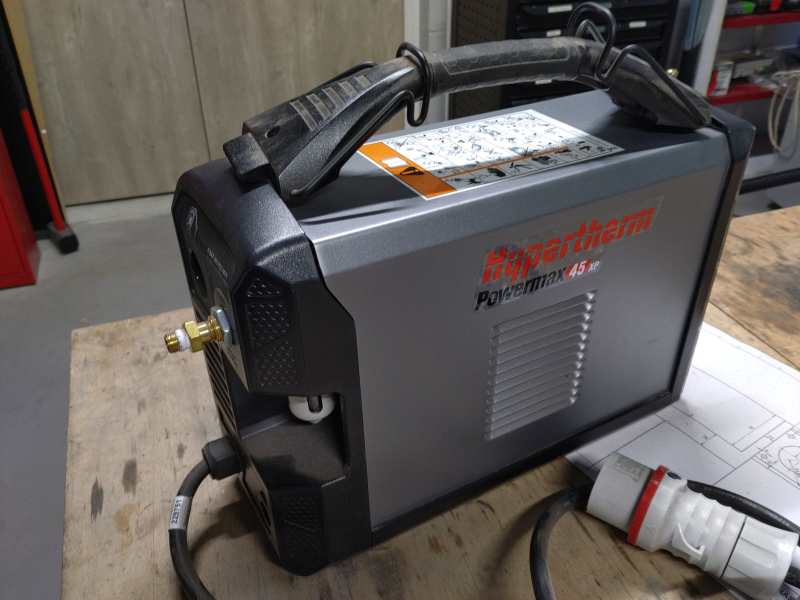
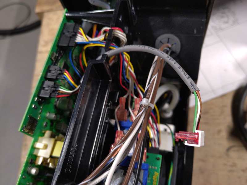
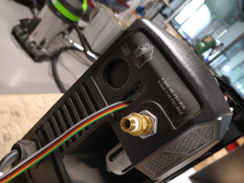
Plasma control
We modified an HyperTherm Powermax45 XP manual plasma cutter. HyperTherm is recognised as a high quality plasma cutter brand. This used high power 3 phases 3 * 400V and a huge amount of air pressure (6 bar) with a dedicated air filtering and cleaning unit.
The unit opened.
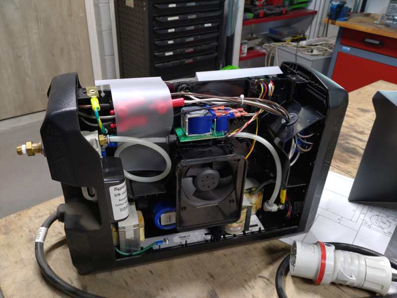
The board installed.
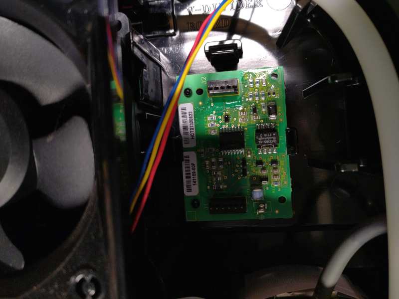
We made dedicated cables and connectors.
Wire path is essential to avoid high power interferences.
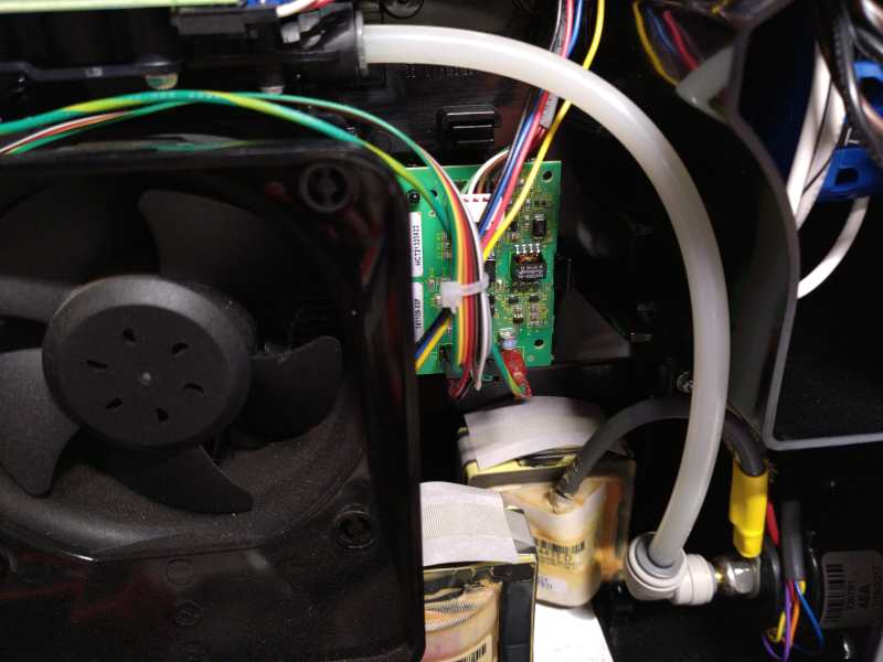
A temporary cable is installed to completely test the command protocol.
First test
Conclusion
This machine allowed us to work together and to improve our skills. It was a pleasant moment to share our knowledge. This device will allow us to be more autonomous in our job and to know all the steps of convection of an agro-equipment.
Useful links
- Stepper motor Arduino tutorial
- HR4988 Datasheet
- Arduino shield Schematic Aranacorp
- Calulator Step per millimeter
- Arduino IDE
- CNCCandle
- GRBL firmware
- Fusion 360
- Agrilab