Final project presentation
Hello and welcome to the Fabacademy page of my final project, pednant 6 months, I participated in the fabacademy training during which I was able to acquire many skills in various areas to be able to prototype quickly.
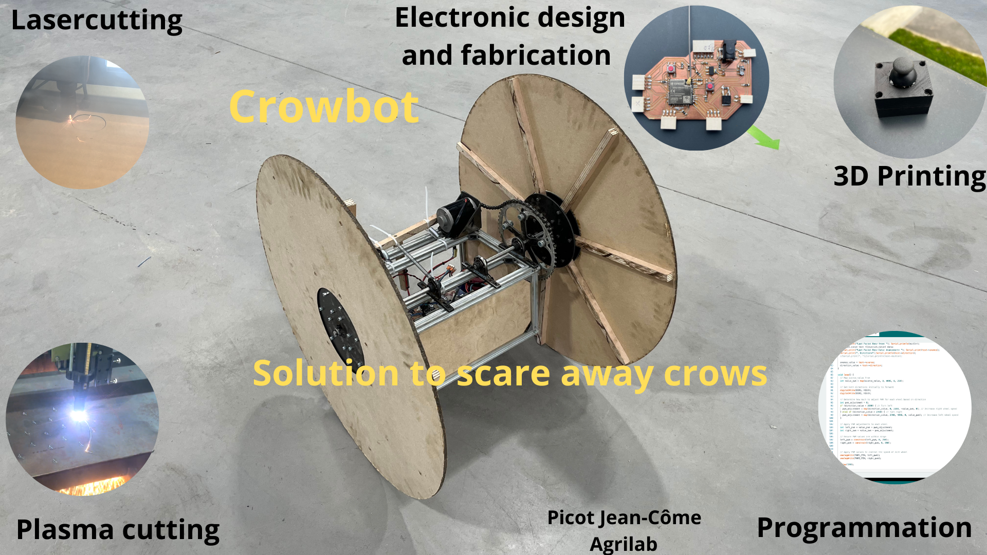
I was able to put his skills to use on my final project, a robot designed to scare corvids away from causing crop damage.
Originally, the robot was intended to be able to move around randomly, making noise to scare them away. However, due to technical problems such as motor underdrive, I was unable to test it in action in the field.
Despite the fact that it didn't manage to move around the fields at the time of evaluation, I still produced a functional robot. You can find the slide and video presentation below.
If you wish to reproduce it, the project is fully documented on this page