Week11. Input devices
Hero shoot
During this 11th week we were mainly interested in Inputs, that is to say the reception of data through electronic circuits. The assignments were as follows:
individual assignment:
measure something: add a sensor to a microcontroller board
that you have designed and read it
group assignment:
probe an input device's analog levels and digital signals
Group assignment:
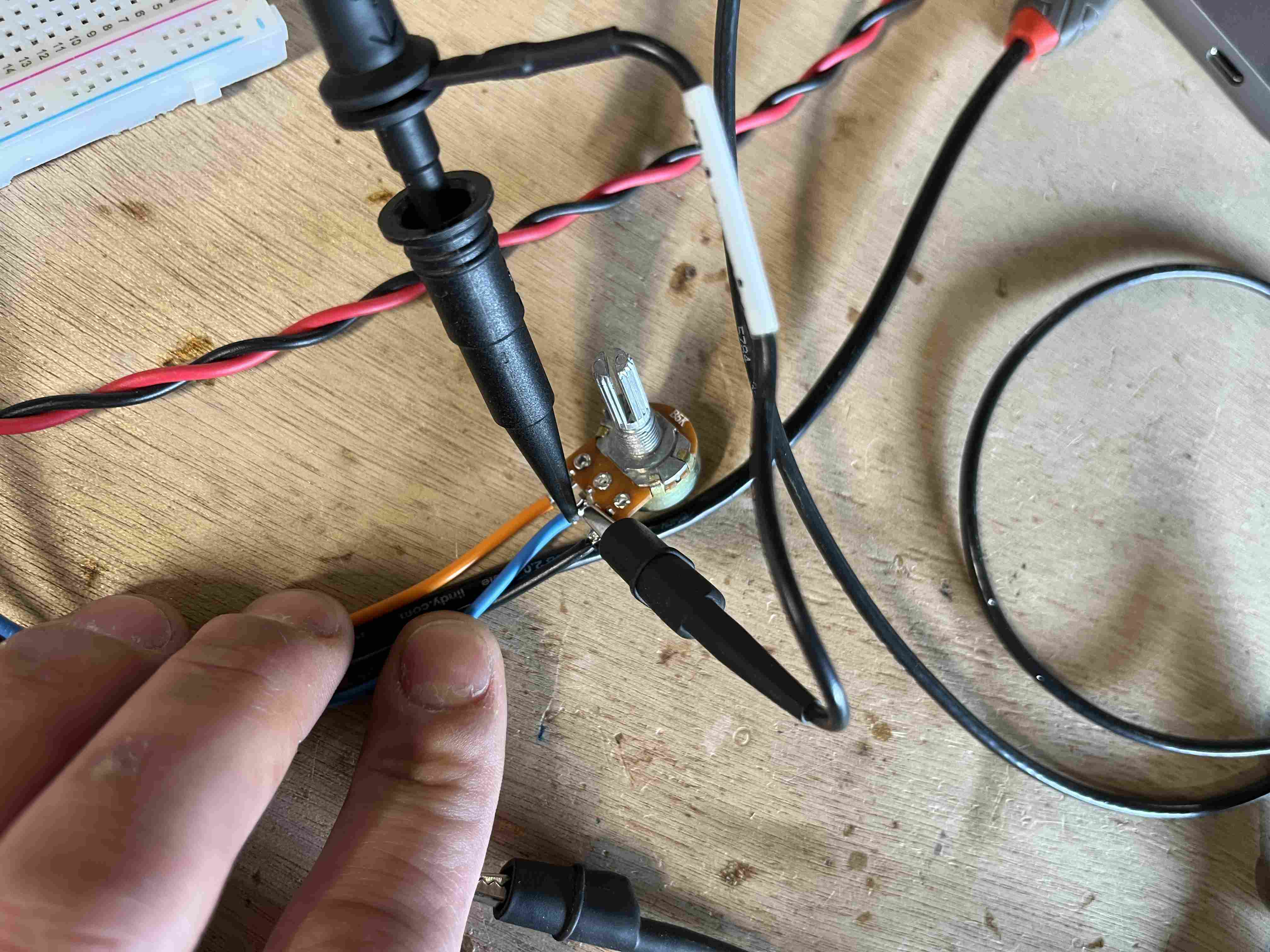
In order to realize my group assignments, I needed to use an analog input. For this, I turned to a potentiometer, as it's a common and often-used sensor, and so it's easy to observe variations. For this, I found a potentiometer of the typeB5K, I then connected it to my esp32 to first read the values it provided on my serial monitor. To do this, I found a code example on this website. I replaced the pin with that of my esp32, which gave me the following code:
// Potentiometer is connected to GPIO 32
const int potPin = 32;

// variable for storing the potentiometer value
int potValue = 0;

void setup() {
  Serial.begin(115200);
  delay(1000);
}

void loop() {
  // Reading potentiometer value
  potValue = analogRead(potPin);
  Serial.print("Analog value: ");
  Serial.println(potValue);
  delay(200);
}
I was able to obtain variable values as required, but on the other hand I wasn't very happy with the way the potentiometer worked. I'd stay on a value of 0 for a long time, then change the value up to 1000, or suddenly reach 3000. The problem could be either the code or the circuit, as the oscilloscope test showed satisfactory results.
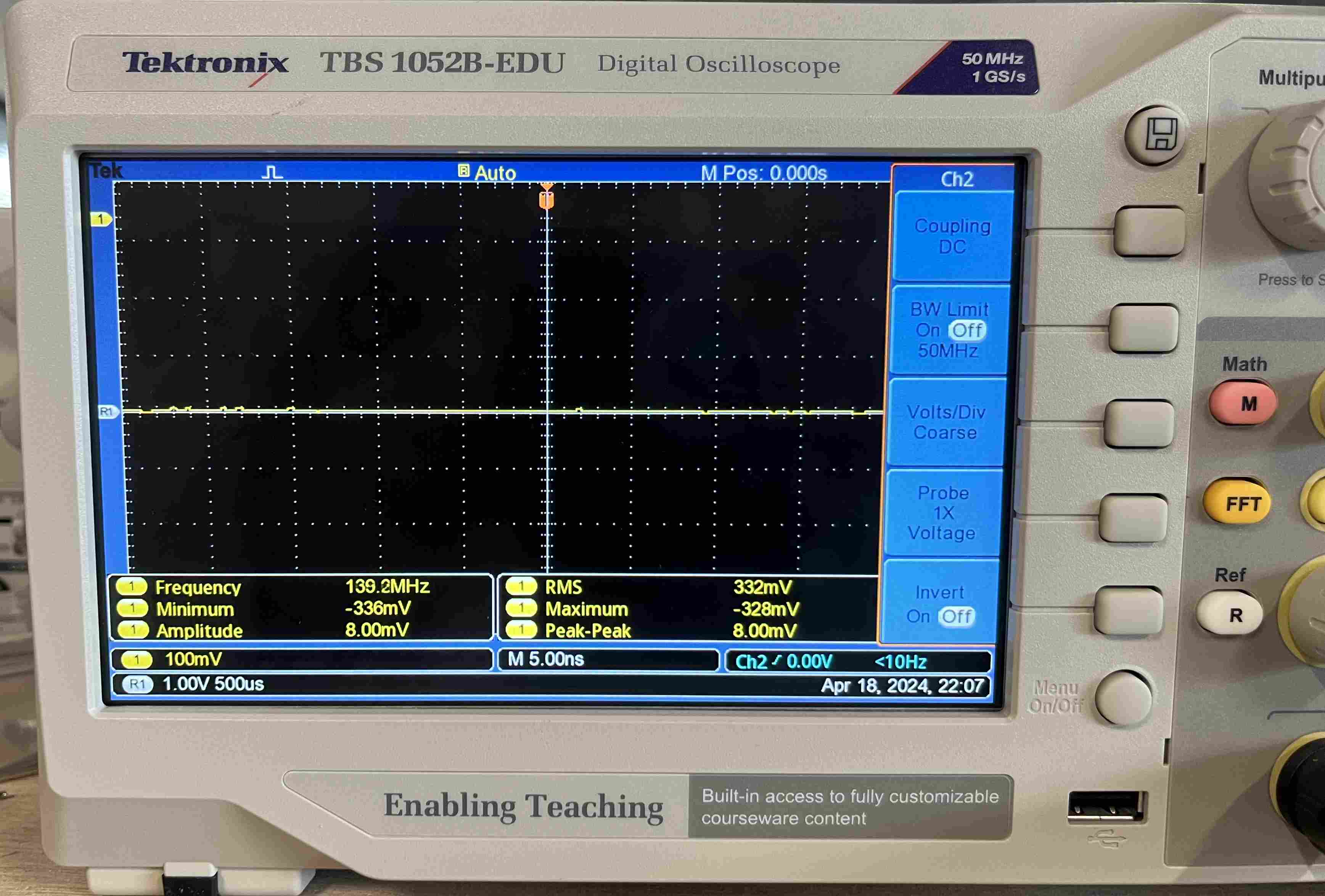
To measure with the oscilloscope, I connected the - clamp of the oscilloscope to ground and the + to the analog readout pin. I then adjusted my oscilloscope so that my voltage was at 0 on the X axis, and I was able to vary my potentiometer to see how the signal evolved.
On the video, we can see that the result is quite satisfactory: when the potentiometer is at 0, we are indeed at 0, and when I turn it to maximum, we have a voltage of 3.3V, which corresponds well to the supply voltage of my potentiometer.
Individual assignment:
Gps
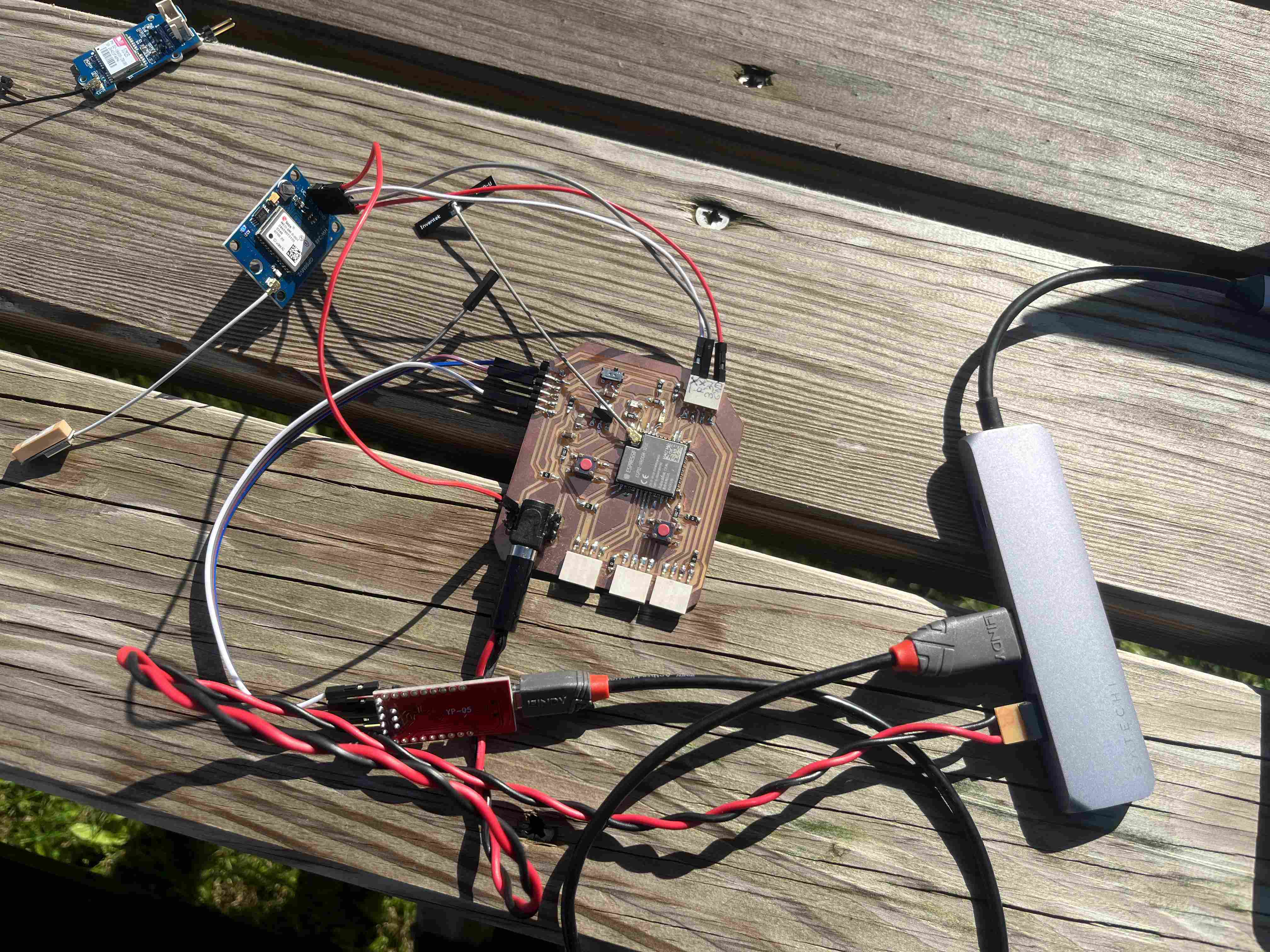
My primary objective during this week was to test a GPS module in order to be able to receive my position. I spent a lot of time trying with different wiring, different power supplies and different codes but it was without success. I first tried with my PCB made during the week 8 Unable to do so, I then tried with an Arduino UNO and this was also unsuccessful..
The GPS module I was trying was this one you should normally try it with the appropriate software u-center which is not available under IOS, I inquired and saw that we could still read the data even without using the software. In order to make it work I used different GPS documentation with esp32 likethis one and this one.I had abandoned the idea of GPS because I had already lost a lot of time with it.
On Tuesday, Nicolas provided me with a new and different GPS module, it is a module GPS NEO-6M, so I retried all the codes that I had tried and without success, I tried with aESP32 dev kit thinking my PCB was faulty but didn't get better results. I then switched to an Arduino Uno and I was not able to receive anything by trying multiple codes that I could find on the internet and I found this guide . It was by following this last step by step that I managed to capture a signal with an Arduino. In order to connect last, you had to connect the following pins:
| Arduino pin | GPS Module pin |
|---|---|
| GND | GND |
| 5V | 5V |
| 3 | RX |
| 4 | TX |
I first followed the tutorial by entering this code:
/*
 * Rui Santos
 * Complete Project Details http://randomnerdtutorials.com
 */

#include "SoftwareSerial.h"

// The serial connection to the GPS module
SoftwareSerial ss(4, 3);

void setup(){
  Serial.begin(9600);
  ss.begin(9600);
}

void loop(){
  while (ss.available() > 0){
    // get the byte data from the GPS
    byte gpsData = ss.read();
    Serial.write(gpsData);
  }
}
I obtained the following values with this code:
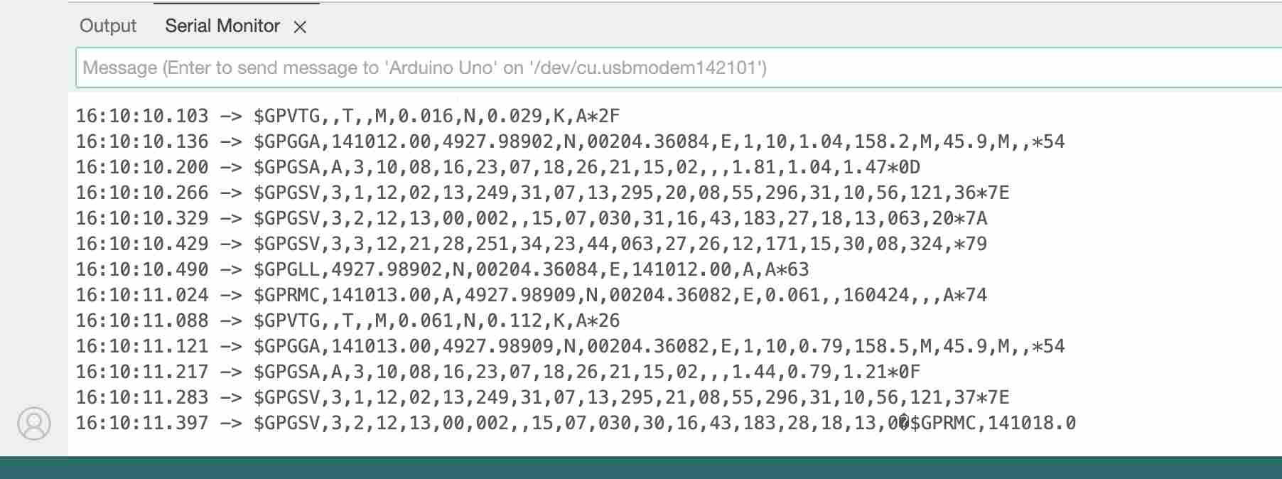
This code is extremely simple, it does not even take into account a library in order to read the data, it simply presents the data provided by the GPS module as it is. While following the tutorial I then downloaded the TinyGPS++ library, I had of course already downloaded it but given my difficulties it was quite simple to follow the tutorial. It is therefore necessary to download the library TinyGPS++. Once the zip file is downloaded, we can unzip it and we obtain a folder named
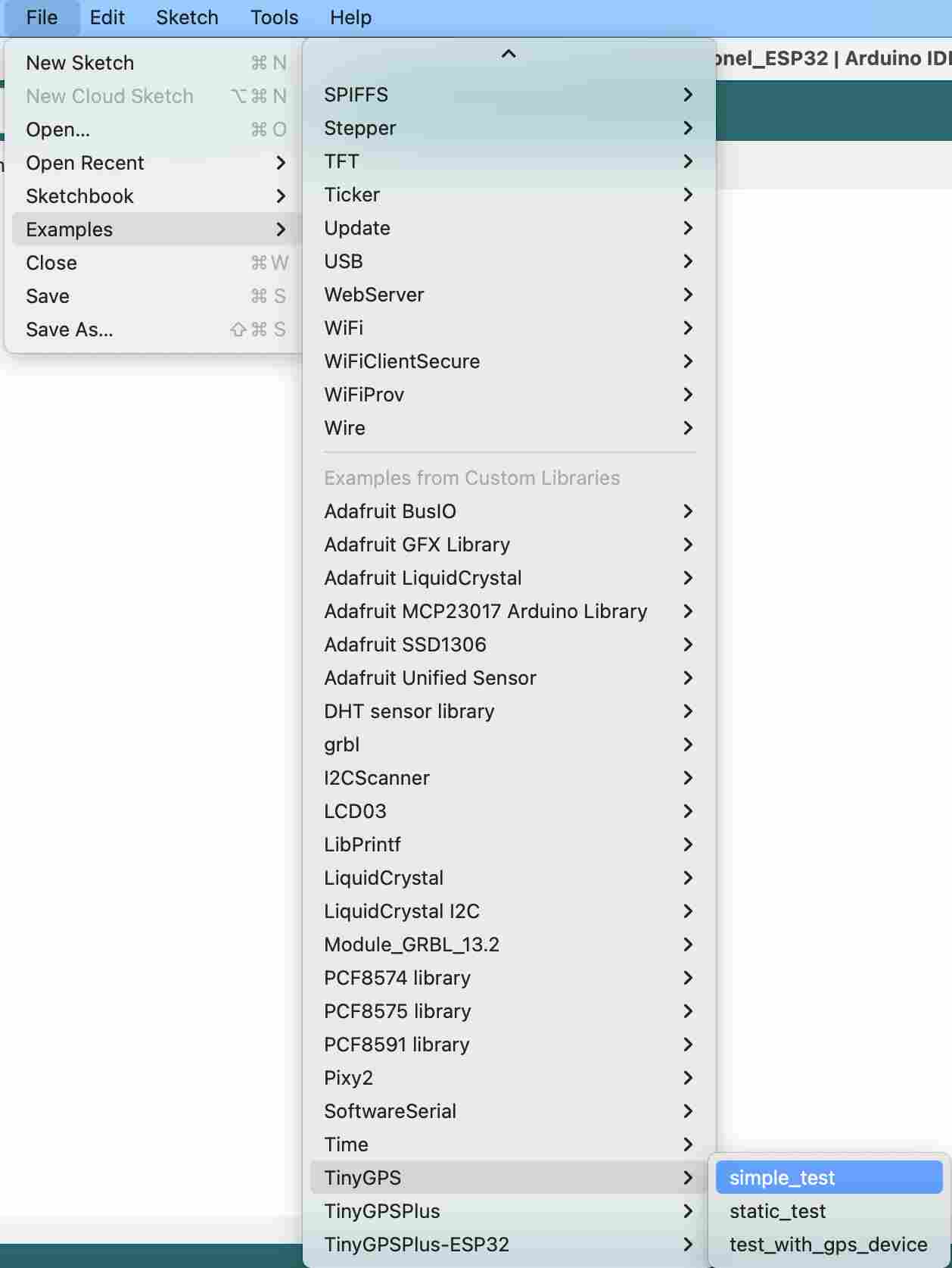
We can then launch our IDE and follow the following path: File > Exemples > TinyGPS > simple_test which will open the test file for us. However, before uploading it, it will be necessary to modify the ss.begin(4800); by ss.begin(9600); on line 16. This modification corresponds to the Baudrate of our module which is different. Once this code was uploaded, I finally managed to read GPS data
I then had to be able to read this data using my ESP32. I modified the original code proposed by the library by replacing the library SoftwareSerial by the libraryHardwareSerial. During the change I also changed the pins which are not the same on the ESP32 and on the Arduino. Following the modifications, the final code that allowed me to read GPS data from the NEO-6M GPS module with my PCB based on an ESP32-Wroom-32UE is as follows:
#include "TinyGPS.h"
#include "HardwareSerial.h"

/* This sample code demonstrates the normal use of a TinyGPS object.
   It requires the use of HardwareSerial, and assumes that you have a
   9600-baud serial GPS device hooked up on pins 16(rx) and 17(tx).
*/

TinyGPS gps;
HardwareSerial gpsSerial(2); // Utilisation du port matériel UART2 de l'ESP32

void setup()
{
  Serial.begin(115200);
  gpsSerial.begin(9600, SERIAL_8N1, 16, 17); // Initialisation du port série pour le GPS

  Serial.print("Simple TinyGPS library v. "); Serial.println(TinyGPS::library_version());
  Serial.println("by Mikal Hart");
  Serial.println();
}

void loop()
{
  bool newData = false;
  unsigned long chars;
  unsigned short sentences, failed;

  // For one second we parse GPS data and report some key values
  for (unsigned long start = millis(); millis() - start < 1000;)
  {
    while (gpsSerial.available())
    {
      char c = gpsSerial.read();
      // Serial.write(c); // uncomment this line if you want to see the GPS data flowing
      if (gps.encode(c)) // Did a new valid sentence come in?
        newData = true;
    }
  }

  if (newData)
  {
    float flat, flon;
    unsigned long age;
    gps.f_get_position(&flat, &flon, &age);
    Serial.print("LAT=");
    Serial.print(flat == TinyGPS::GPS_INVALID_F_ANGLE ? 0.0 : flat, 6);
    Serial.print(" LON=");
    Serial.print(flon == TinyGPS::GPS_INVALID_F_ANGLE ? 0.0 : flon, 6);
    Serial.print(" SAT=");
    Serial.print(gps.satellites() == TinyGPS::GPS_INVALID_SATELLITES ? 0 : gps.satellites());
    Serial.print(" PREC=");
    Serial.print(gps.hdop() == TinyGPS::GPS_INVALID_HDOP ? 0 : gps.hdop());
  }

  gps.stats(&chars, &sentences, &failed);
  Serial.print(" CHARS=");
  Serial.print(chars);
  Serial.print(" SENTENCES=");
  Serial.print(sentences);
  Serial.print(" CSUM ERR=");
  Serial.println(failed);
  if (chars == 0)
    Serial.println("** No characters received from GPS: check wiring **");
}
In order to put my code, I connected the pins in the following way.
| Arduino pin | GPS Module pin |
|---|---|
| GND | GND |
| 5V | 5V |
| 16 | RX |
| 17 | TX |
I was then able to put the code on my ESP32 and read the data, and finally after two days of trying to get the GPS to work, I succeeded and got the following values with this setup:
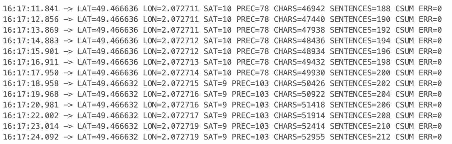
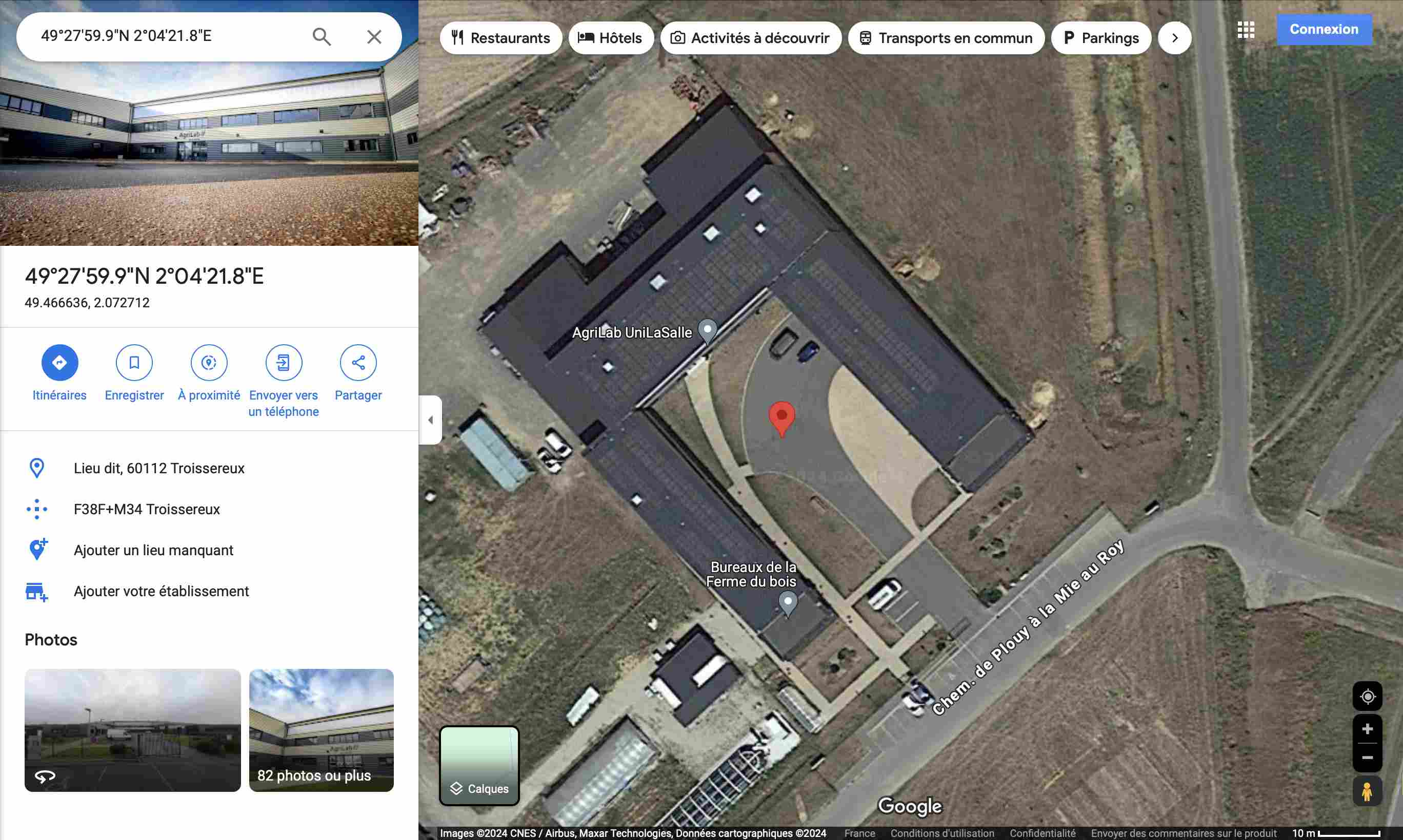
In order to check the consistency of the data received I went to check it on google maps by entering them in the search bar as follows Lattitude , Longitude so in my case 49.466636 , 2.072712.When I launch the search, the GPS positions me well in front of Agrilab, where I carried out my tests.
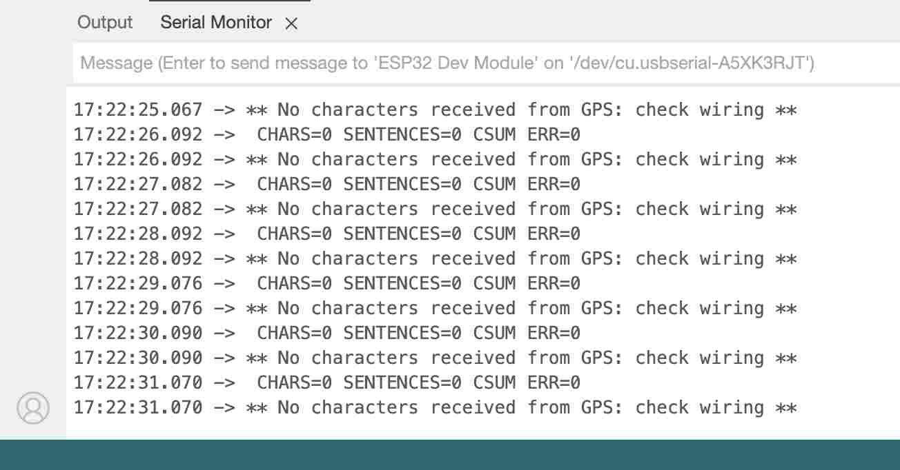
Following this success I then wanted to try to read the data with the first module I used and I still did not succeed using the same code. All I got were the following messages:
Sonar
I was somewhat concerned about not being able to read a GPS signal and therefore wanted to test my circuit with another input. I therefore chose to test a type sonarHC-SRO4. In order to help me connect and control this type of sensor I used this website, documentation of Théo Gauthier as well as this datasheet.
In order to read the distance I used the following code:
int trig = 32;//the pine tree that emits the ultrasound
int echo = 33;//the pine tree that receive the ultrasound
long lecture_echo;
long cm;

void setup(){

pinMode(trig, OUTPUT);
digitalWrite(trig, LOW);
pinMode(echo, INPUT);
Serial.begin(115200);//sensor baudrate

}

void loop(){
//sends ultrasound for 100 microseconds, then stops
digitalWrite(trig, HIGH);
delayMicroseconds(100);
digitalWrite(trig, LOW);
//read the value and convert it into cm
lecture_echo = pulseIn(echo,HIGH);
cm = lecture_echo /58;
//displays the result
Serial.print("Distance in cm :");
Serial.println(cm);
delay(1000);
}
After searching for a long time why I couldn't get consistent values, I finally realized that I was supplying my sensor with 3.3V and not 5V. By testing with a workshop power supply I had values. Since my esp32 did not have a 5V output, I decided to solder pins directly to the power supply. I know that it is not very good and conventional but by checking with the multimeter I have a 5V power supply. On the other hand, if you repeat this operation, be very careful. This assembly works because I power my PCB with the USB of my computer which outputs at 5V if you put a higher voltage the sonar will receive more current and you risk damaging it.
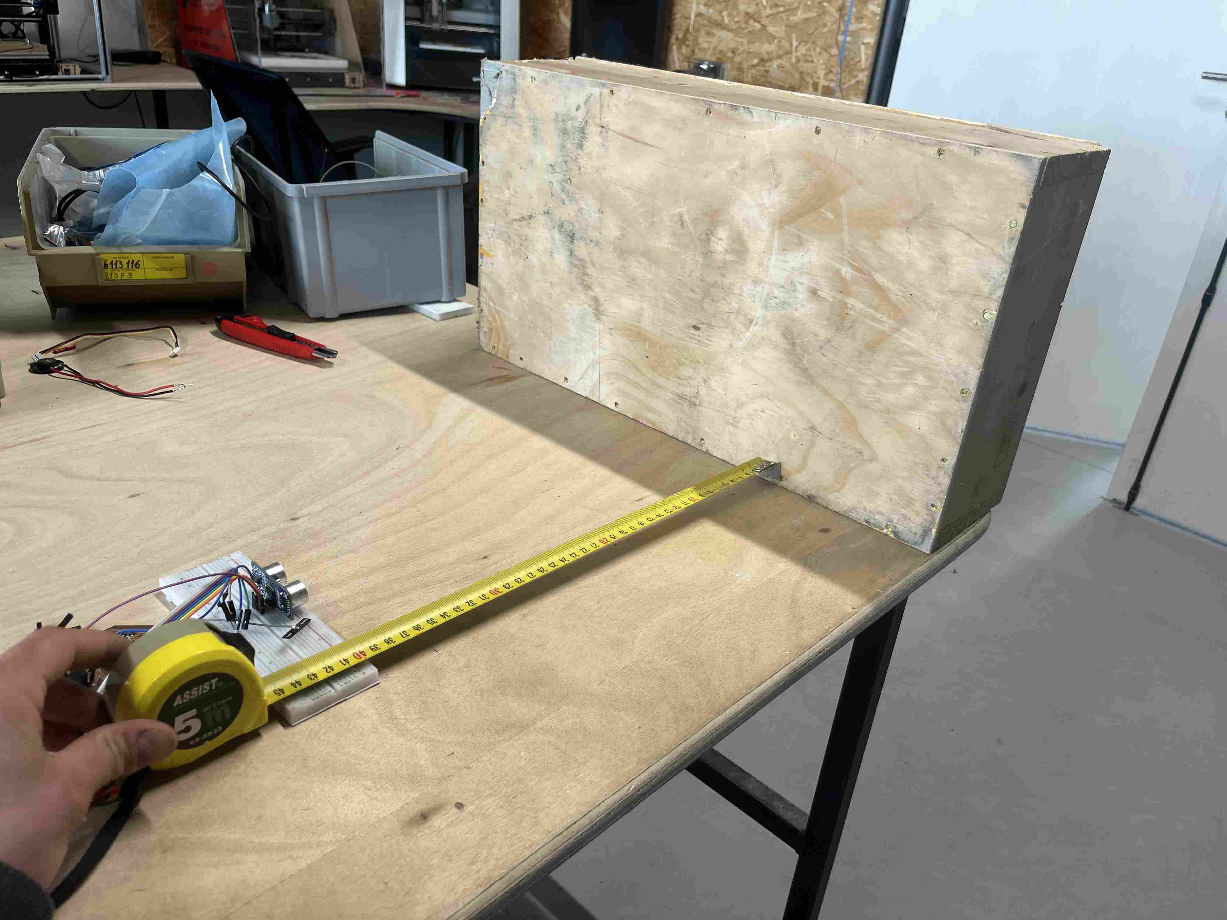
Once my setup was working well I was able to test it at different distances to see if the results were satisfactory or not at all. To do this, I placed my sensor in front of a wooden box and moved back as I went. I did this test indoors which may have some variability in the quality of the results.
JI got the results below:
| Real distance(in cm) | Measured distance |
|---|---|
| 10 | 11 |
| 20 | 20 |
| 30 | 30 |
| 40 | 39 |
| 50 | 49 |
| 60 | 59 |
| 70 | 69 |
| 80 | 79 |
| 90 | 88 |
| 100 | 98 |
| 110 | 109 |
| 120 | 107 |
| 130 | 117 |
| 140 | 138 |
| 150 | 149 |
We can see that the values are quite consistent up to 1m20 and 1m30 where they display values 10cm lower, beyond that they again give coherent values but oscillate with lower values. I repeated the test and it is only between 1m20 and 1m30 that the values are 10cm lower. This type of sensor is therefore effective but especially at fairly close values (1m) and with a measurement precision which is not precise to the nearest cm. The lack of precision of these values may be due to the fact that I do not measure the time which passes between the transmission and reception of the signal, this code should therefore be improved in order to have better precision. Today it is interesting to test this type of sonar but there are less expensive and more precise alternatives.
Touch sensor
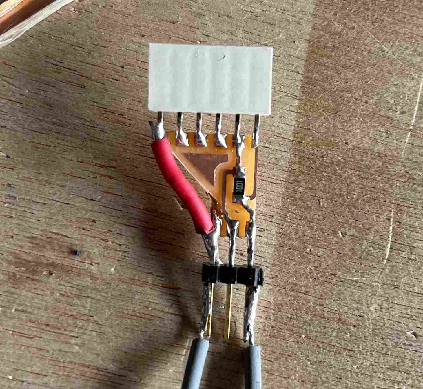
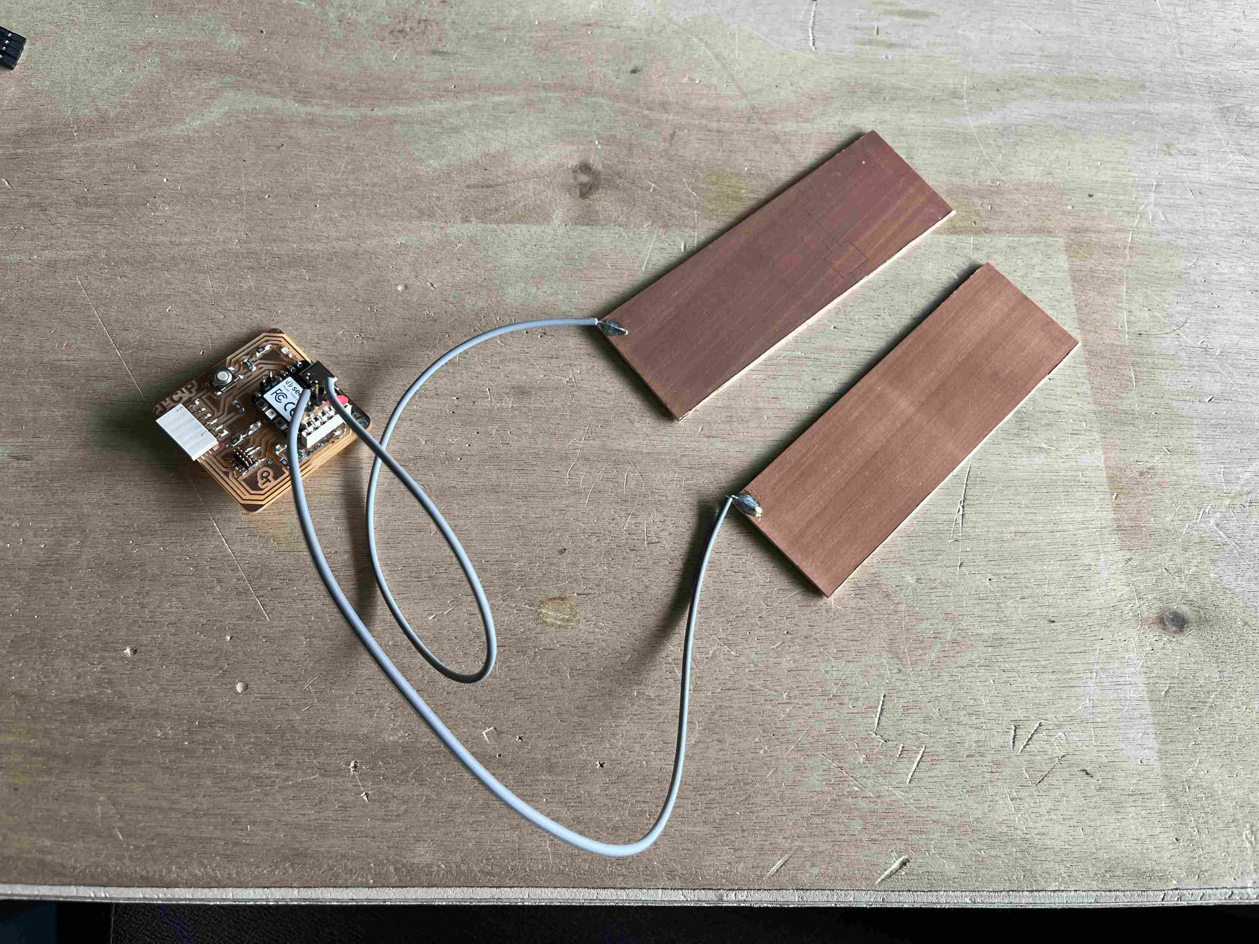
I then wanted to reproduce a test carried out by Neil to measure the conductivity between two copper plates. It isthis one. For this, I did not want to redesign a circuit and therefore made an adapter to connect this plate to my quentorres. You can find the files here traces and the interrior. The file that I milled had borders too close to the tracks which partially cut them off. The version I put above has not been tested but has been corrected on kicad.
In order to read the data I wanted to stay on the Arduino IDE and so I tried to translate the code provided by Neil using Chat gpt in C++. The code used was the following:
#define PIN_IN 2

void setup() {
  pinMode(PIN_IN, INPUT);
  Serial.begin(9600);
}

void loop() {
  unsigned long loop_time = 250; // Loop time in microseconds
  unsigned long settle_time = 50000; // Settle time in microseconds
  unsigned long step_time = 0;

  // Charge the output pin for "loop_time" microseconds
  pinMode(PIN_IN, OUTPUT);
  digitalWrite(PIN_IN, HIGH);
  delayMicroseconds(loop_time);

  // Measure rise time
  pinMode(PIN_IN, INPUT);
  unsigned long start_time = micros();
  while (digitalRead(PIN_IN) == LOW) {
    // Wait for the input pin to go high
    if (micros() - start_time > settle_time) {
      // If settle time is exceeded, exit loop
      break;
    }
  }
  step_time = micros() - start_time;

  Serial.print("Rise time: ");
  Serial.print(step_time);
  Serial.println(" µs");

  delay(1000); // Wait for 1 second before next measurement
}
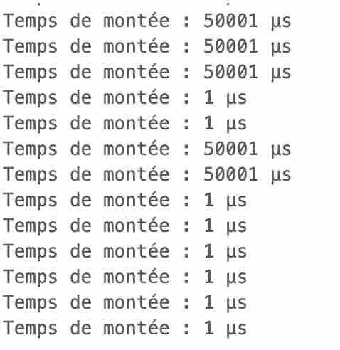
This code was not a great success, I was not able to read variable values. The only results I got were 1μs when I did nothing and 50001μs when I touched the plates. This test was not very conclusive and I did not want to waste time with this test, so I did not look for a way to read in a better way.
SHT3X
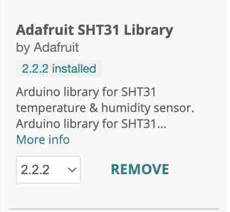
During the week Embeded programming, I used a type sensor DHT11 for measuring humidity and temperature. Our instructors informed us that the reading quality of these sensors was not very satisfactory and that is why I am trying it. SHT3X For this, I followed the same procedure as with my GPS, I tested it under arduino and when the program worked, I modified the code so that it worked on ESP32. In order to read its values, it is necessary to download the library Adafruit SH31.
Once downloaded, I used the example code from the library. I took the code provided by the library and adapted it for my ESP32, for example by changing the pins which in my case are theGPIO2 for SDA and the GPIO14 for SCL.The code I used to read the sensor with my ESP32 is:
#include "Wire.h"
#include "Adafruit_SHT31.h"

bool enableHeater = false;
uint8_t loopCnt = 0;

Adafruit_SHT31 sht31 = Adafruit_SHT31();

void setup() {
  Serial.begin(9600); // Initialize serial communication for debugging
  Wire.begin(2, 14); // Configure SDA and SCL pins for I2C communication

  while (!Serial)
    delay(10); // Wait for the serial console to open

  Serial.println("SHT31 test");
  if (!sht31.begin(0x44)) { // Set to 0x45 for alternate i2c addr
    Serial.println("Couldn't find SHT31");
    while (1)
      delay(1);
  }

  Serial.print("Heater Enabled State: ");
  if (sht31.isHeaterEnabled())
    Serial.println("ENABLED");
  else
    Serial.println("DISABLED");
}

void loop() {
  float t = sht31.readTemperature();
  float h = sht31.readHumidity();

  if (!isnan(t)) { // Check if 'is not a number'
    Serial.print("Temp *C = ");
    Serial.print(t);
    Serial.print("\t\t");
  } else {
    Serial.println("Failed to read temperature");
  }

  if (!isnan(h)) { // Check if 'is not a number'
    Serial.print("Hum. % = ");
    Serial.println(h);
  } else {
    Serial.println("Failed to read humidity");
  }

  delay(1000);

  // Toggle the heater state every 30 seconds
  // An increase of ~3.0 degC temperature can be noted when heater is enabled
  if (loopCnt >= 30) {
    enableHeater = !enableHeater;
    sht31.heater(enableHeater);
    Serial.print("Heater Enabled State: ");
    if (sht31.isHeaterEnabled())
      Serial.println("ENABLED");
    else
      Serial.println("DISABLED");

    loopCnt = 0;
  }
  loopCnt++;
}
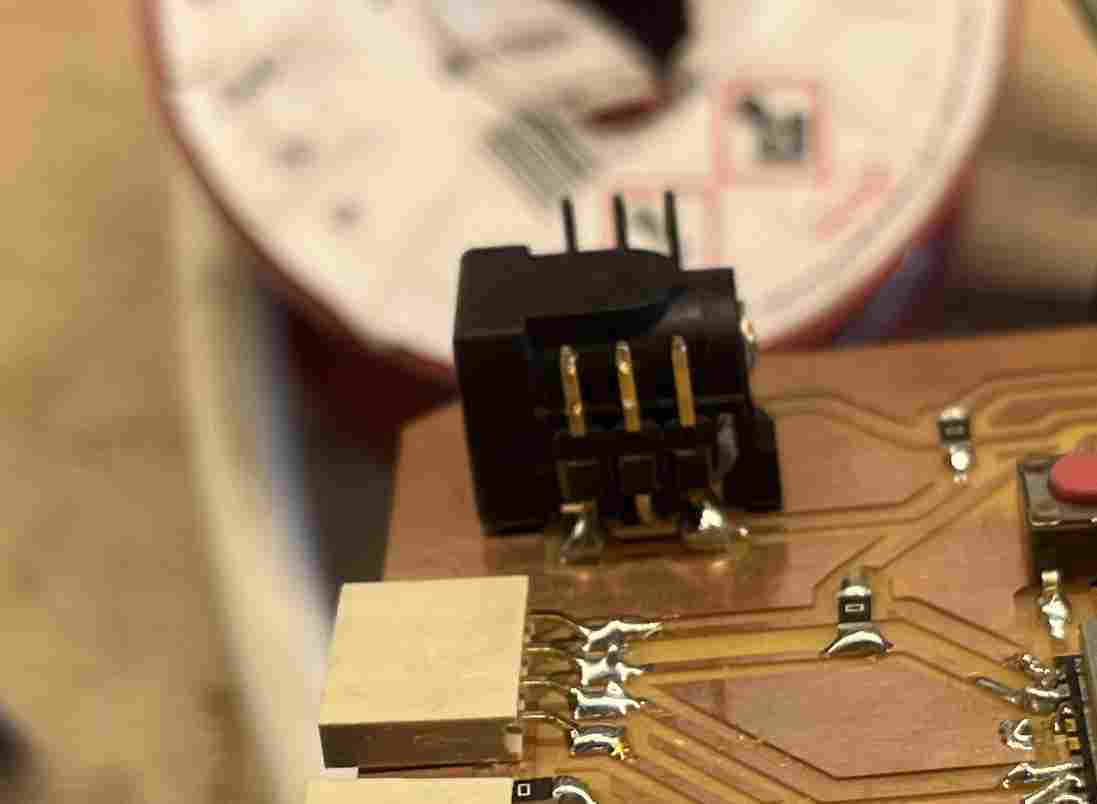
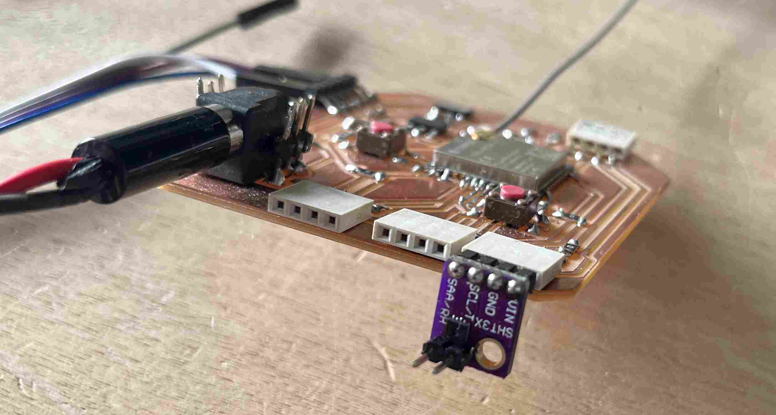
The sensor pins fell right with the I2C output of my PCB, so I was able to plug it directly into it
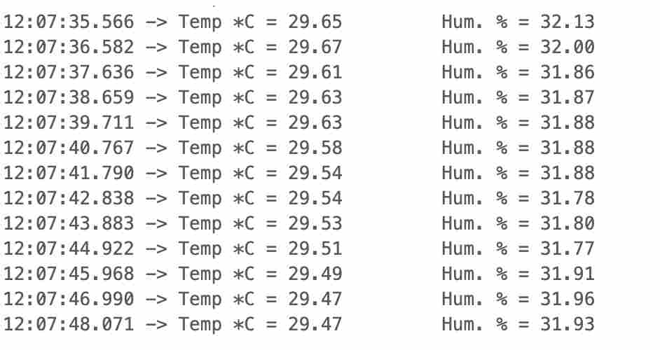
The results I obtained in the serial monitor were satisfactory
Code files
SHT3X
GPS ESP32
Potentiometer test
Sonar test
copper plate test