During week 8, we focused on electronic circuit design, with the following assignments:
group assignment:use the test equipment in your lab to observe the operation
of a microcontroller circuit board
send a PCB out to a board house
individual assignment:
use an EDA tool to design a development board to interact
and communicate with an embedded microcontroller,
produce it, and test it
extra credit: try another design workflow
extra credit: design a case for it
extra credit: simulate its operation
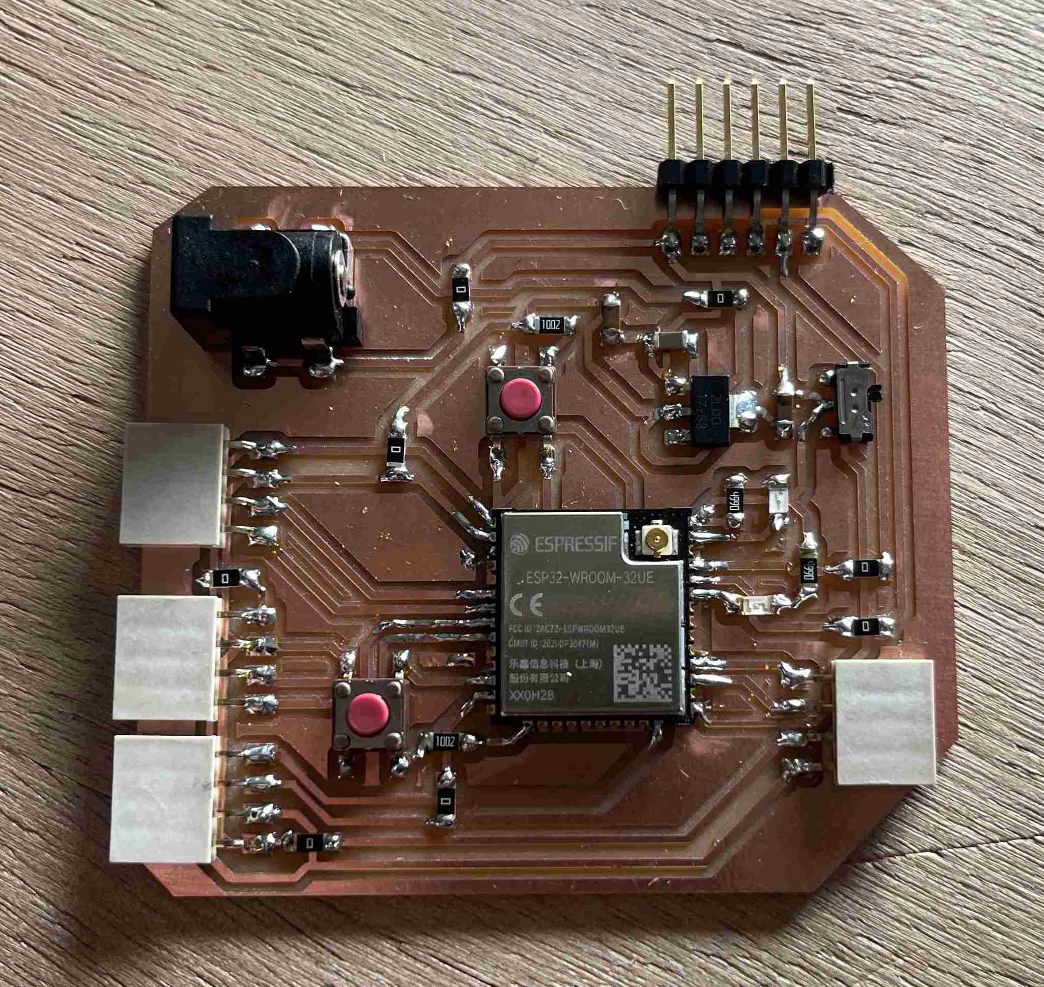
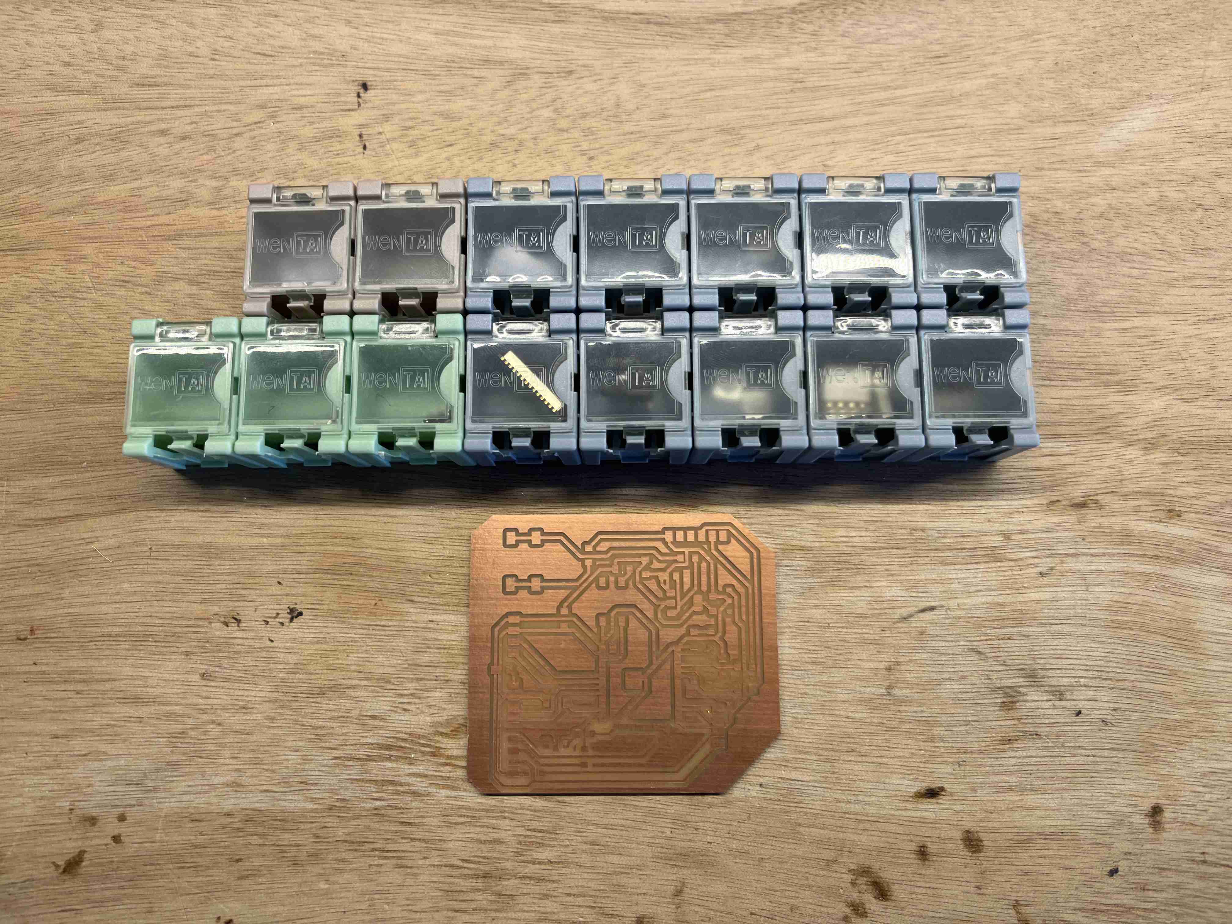
Hero Shoot
Group assignment:
You can find all of our group assignments on the Agrilab page of the week
Individual assignment:
In order to fulfil my individual assignments, I had to design a printed circuit board, so I chose to make a circuit that could be useful for my final project. As I didn't yet have a clear idea of what my robot would look like and what functions it would have, I chose to focus on just a few functions for the time being, i.e. movement using two electric motors and localisation using a GPS signal. I also need to be able to control the robot remotely.
Microcontroler
The first thing that had to be done to design this project was to choose a microcontroller, given that I wanted to have wifi and Bluetooth access, so my choice fell on an ESP32. We have various models at Agrilab and I finally chose to use a ESP32-WROOM-32UE. It's quite compact and still has 38 pins, which means it can be used in a variety of ways, so I've obviously got the network functionality. To start working on it, I spent a long time reading the datasheet to determine how I could use each pin and where to connect them.
As I only have a brief knowledge of electronics, I used the map below as an example, which was itself inspired by this design from Neil, It also has its own power supply via a barrel and a LED. Using this existing board as a support means I already have a functional environment that I can programme easily and that works with the same microncontroller I've chosen to use.
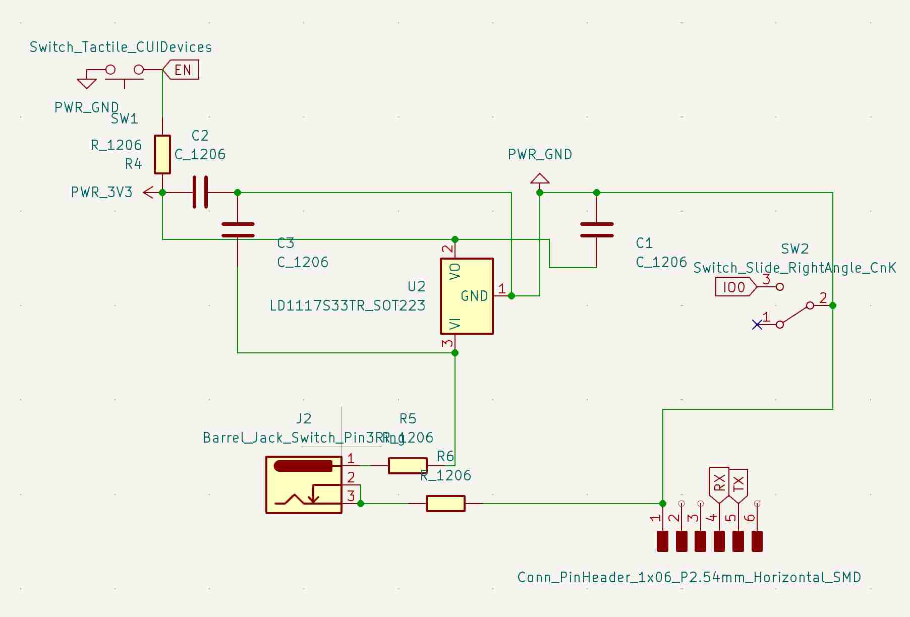
So I decided to create a new circuit based on this example, to which I added 4-pin header pins for different uses:
-2 to control my motor drivers with pins and power supply
-One to receive GPS data with the power supply as well as RX and TX pins
-An I2C output so I can plug in a screen if I want to.
In addition to these outputs, I've added an extra LED and a button
To program this board, I adjusted the RX and TX pins so that it could be programmed using the Quentorres
Kicad
To design this circuit, I used Kicad which is open source software for designing electronic circuits. To get to grips with the software, we had a workshop to learn how to use it on Thursday so that we could master it and reproduce our own circuit. To practise, we tried to reproduce the SAMDino
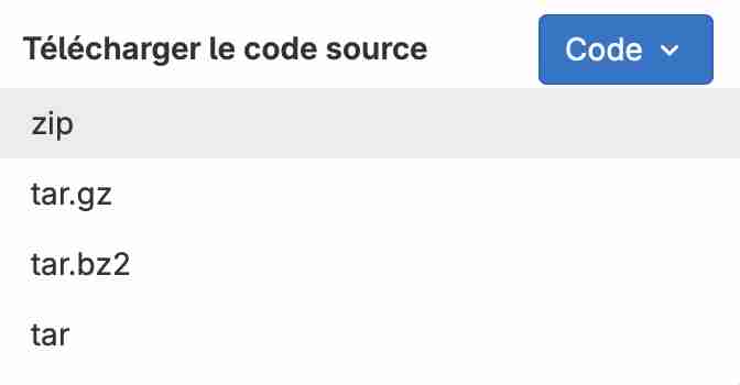
Before you even start, it's a good idea to download the Kicad of the Fabacademy which is made up of a number of extremely useful components. To download it, simply click on code then download the zip file
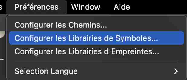
Once the library has been downloaded, you can launch kicad. In the preferences menu, select configure symbol libraries. A new window will open in which you can click on + to add a library, we'll give it a nickname and then look in the unzipped folder for the file fab.kicad_sym, we will then do the same process for the footprints by searching for the file fab.pretty, we can then validate again and use our libraries.
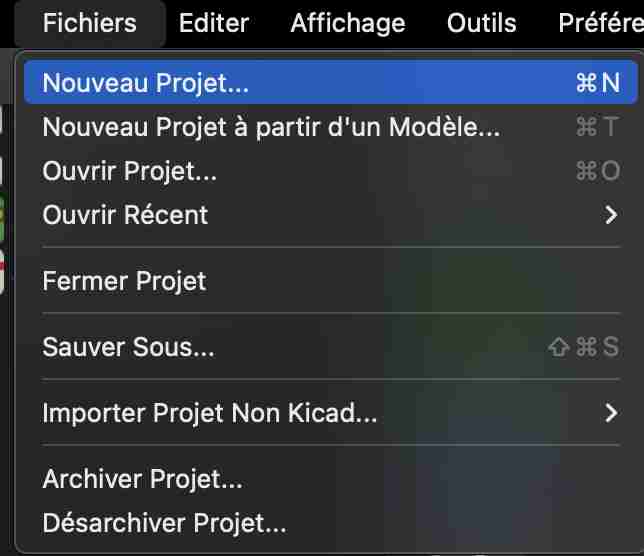
You can then go to the file tab and create a new project that you can name and put in the desired location.
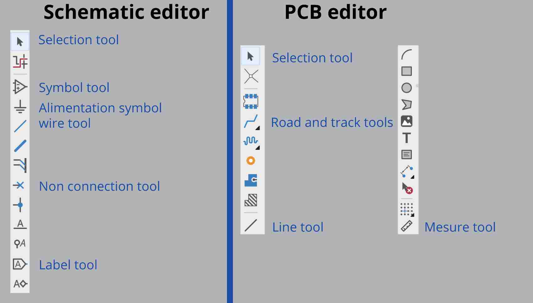
Below is a presentation of the various tools available, including those for the schematic editor and the PCB editor.
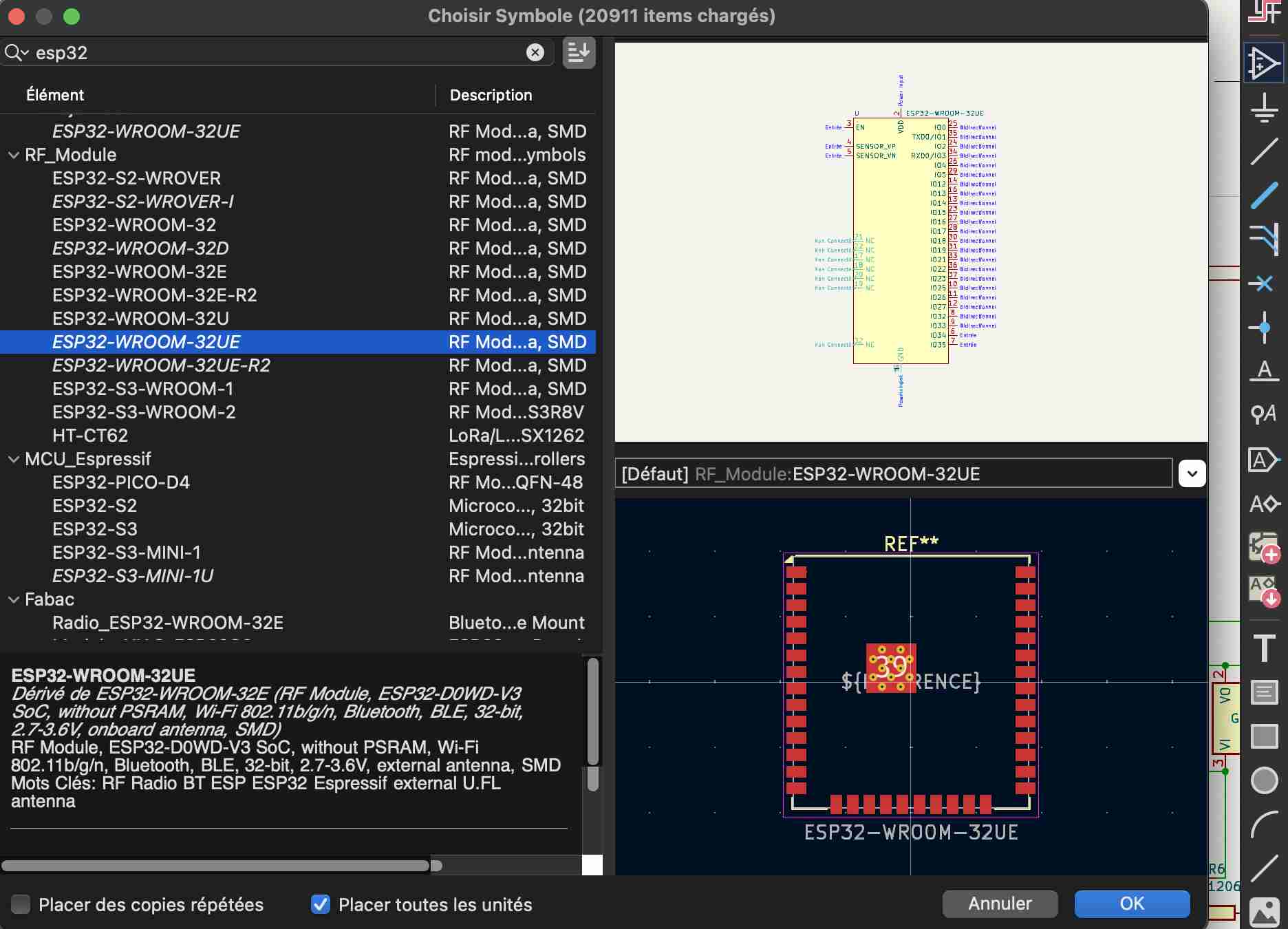
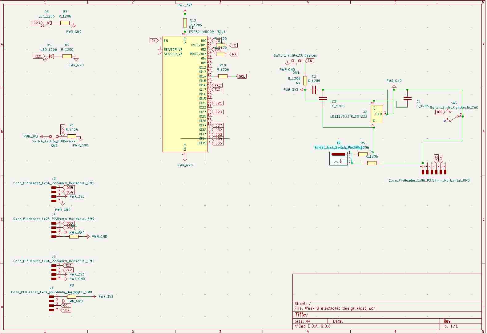
Once the project has been created, you can go to the schematic editor to start creating your circuit. You can start by using the add symbol tool on the right to search for the different components you want to add, for example here my ESP32-WROOM-32UE microprocessor, so you can add the different elements you want to put in our circuit by searching for them in the same way. You don't necessarily know which components you want to add to the list, so you need to compare and don't hesitate to consult the datasheets to be sure. For example, in the case of pinheaders, having only used surface elements, I know that this type of component is always followed by the acronym SMD.
The next most common step is to add the power supply symbols, often 5V, 3.5V and a ground. To do this, go to the power supply symbol tool and select the one you want.
Connecting our elements
Once our elements are in place, we can link them in two different ways:
-With labels
-With wires
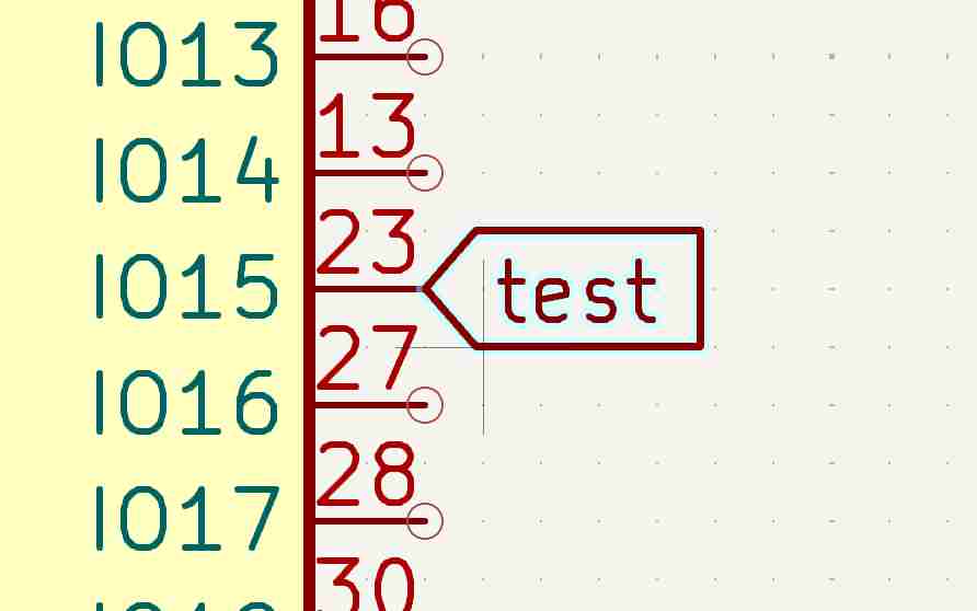
To connect them with labels, click on the label tool, a window will open where you can name your label, then click on enter and you can place the label where you want it, then copy the label and paste it where you want to place the other component.
To use the wire tool, simply connect the connections of the elements you want to join together, or use the add wire tool to link the components you want, as shown below.
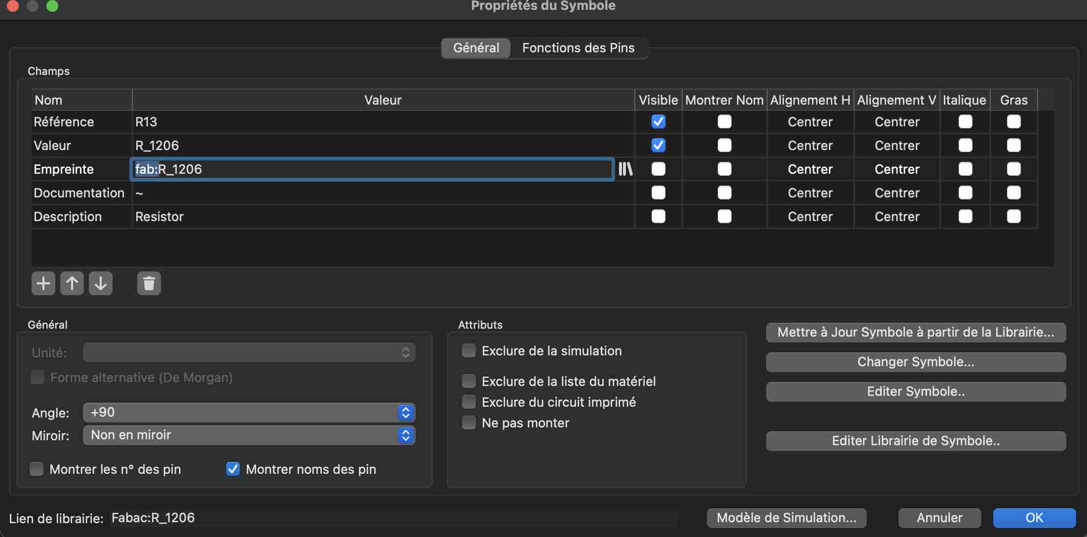
You can then use other tools, such as the no connection tool, to indicate unused pins. To do this, simply use the selection tool and double-click on the component you want to use. A window will open showing the various properties of our component. You can click on the library icon on the footprint line and then go and find the footprint you want. For components in the fabacademy library, simply remove the fab:to find the right footprint.
Once you've changed all your fingerprints, you can click on the function at the top of the screen. Open the PCB in the PCB editor which will open up our PCB editor
Once in the pcb editor, we can place our components on either side so that the paths can be made without too many problems, i.e. without crossing each other and trying to take up as little space as possible, bearing in mind that the tighter the components, the more complicated they will be to solder, and don't forget to take into account the thickness of the tracks.
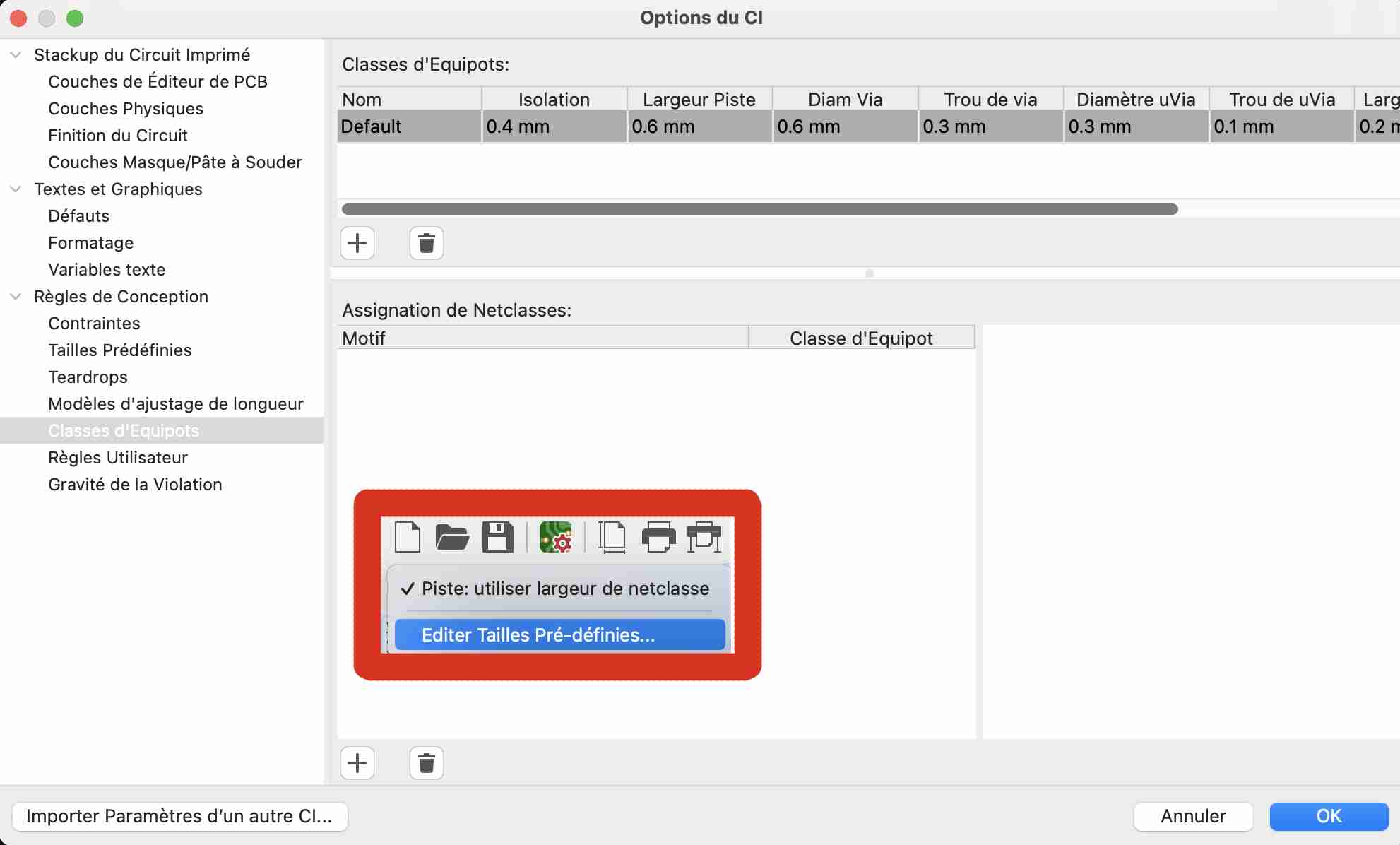
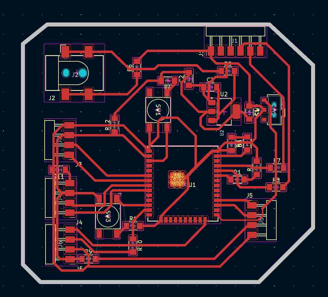
When all the components are positioned correctly and you can see little or no blue lines crossing each other, you can start adding the tracks. We're going to make sure that we draw the tracks so that we have the simplest possible chmins, so we use the track route tool on the right-hand wheel. To modify the characteristics of my tracks I went to the Edit Preset Sizes tool and then to the Equipotential Class where I modified two main values. Firstly, I increased the insulation to 0.4mm and the track width to 0.6mm. This step is essential, firstly because the milling cutters we usually use are 0.4mm, so it's essential to leave at least the space of one milling cutter between two tracks so as not to mill the roads. The wider tracks allow better current flow and heat dissipation. The esp32 is a microcontroller that requires a lot of current, so it's essential to have tracks that let more current through.
Once all our components and tracks are in place, we can draw the outline of our circuit. To do this I went to a different layer in my case user1 and I used the line-drawing tool to draw the outline of my circuit, taking care to draw a 1mm line which corresponds to the diameter of the milling cutter we use to cut the outline of our PCBs. Once these steps have been completed, our PCB is ready to be exported for milling. I'm not very happy with my design, I didn't arrange the space on my circuit properly and to compensate for the poor arrangement of the elements, I had to add 9 0Ohm resistors on my circuit to act as a bridge to pass over the wires.
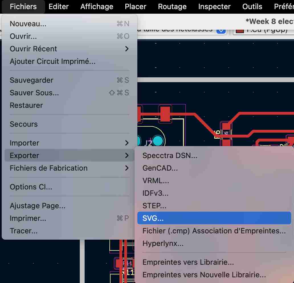
Once all these steps have been completed, we can export our PCB. To do this, go to Files> Export> SVG to open a new window. Then choose the layer you want to export and various parameters such as the page format, etc. Finally, click on Export
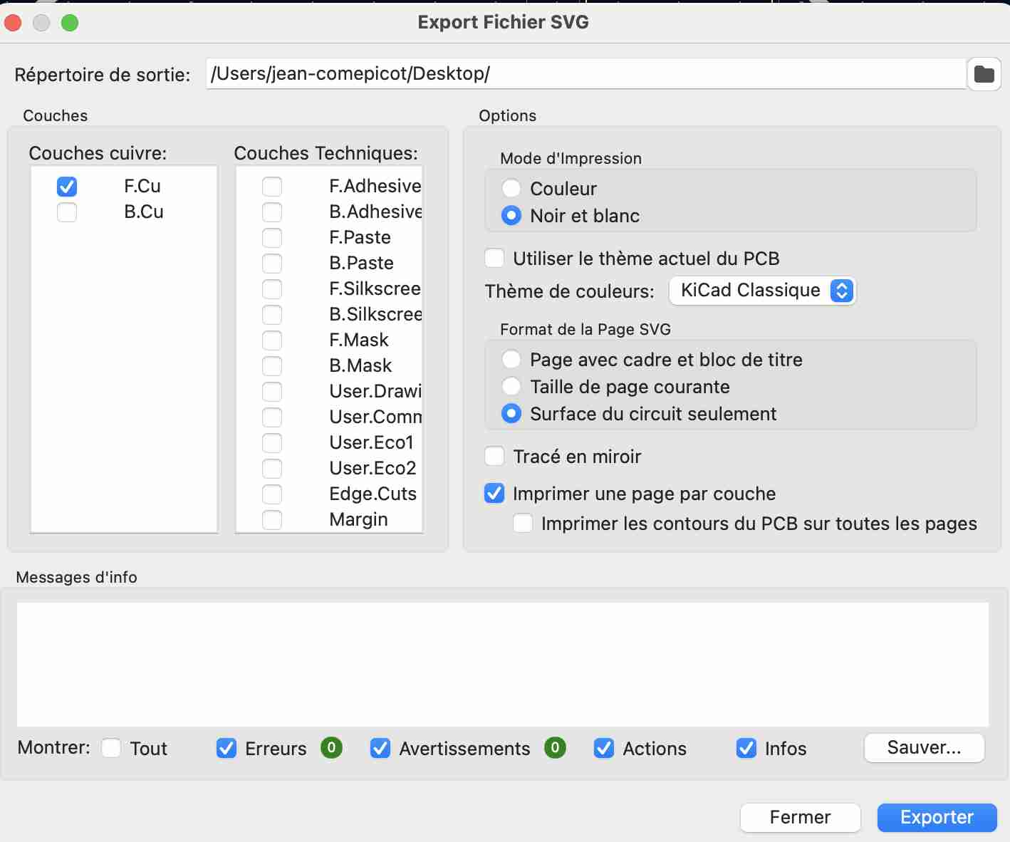
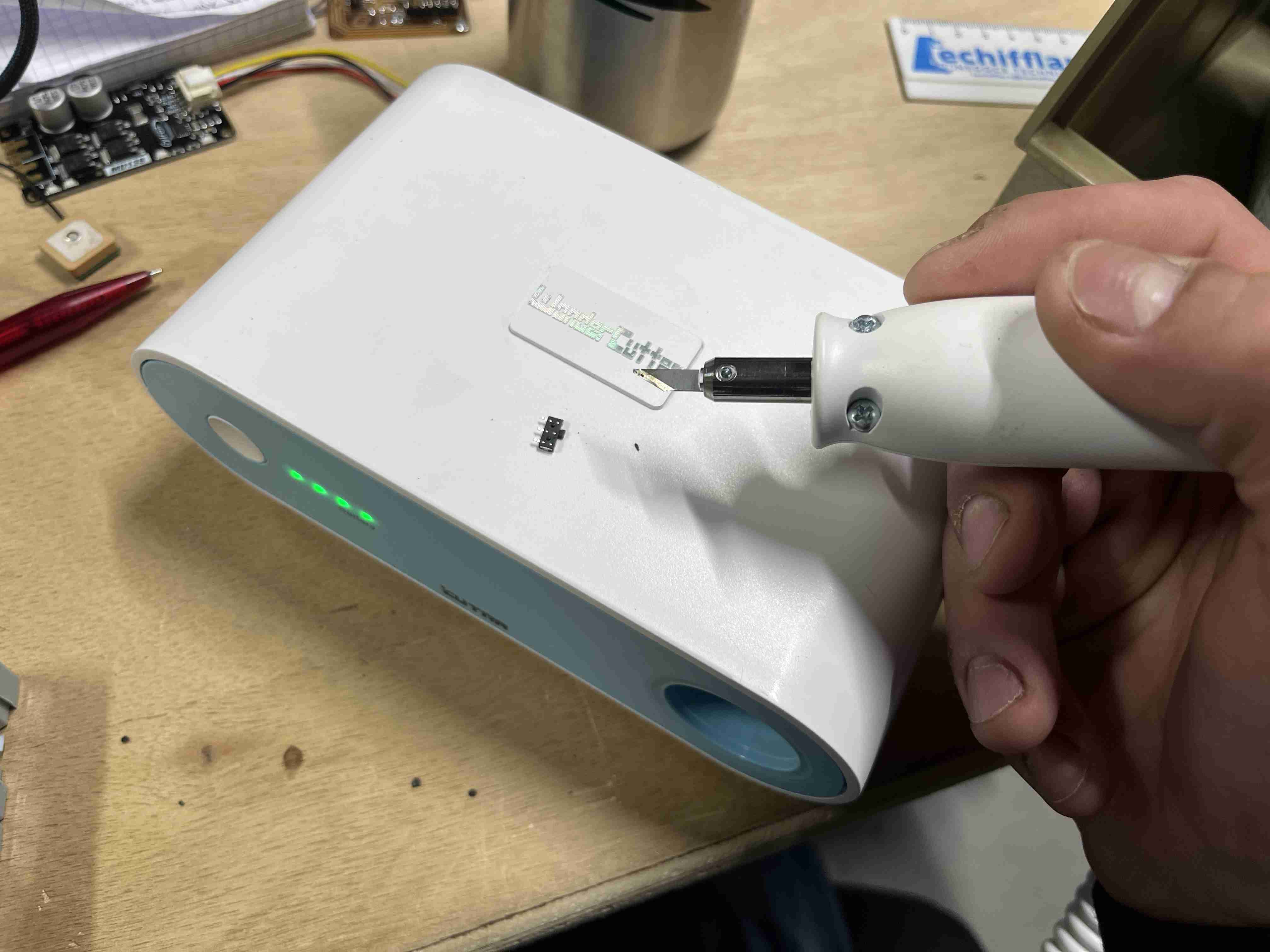
In my case, I exported two layers, the trace layer and the outline layer. I should normally have exported a third layer which corresponded to the holes I needed to make, but I couldn't do it and I was pressed for time. These holes corresponded to the plastic pins that were on the underside of the button and the feed barrel. To save time and avoid having to drill in these places, I used an ultrasonic cutter to cut out the protruding pieces of plastic to create a flat surface.
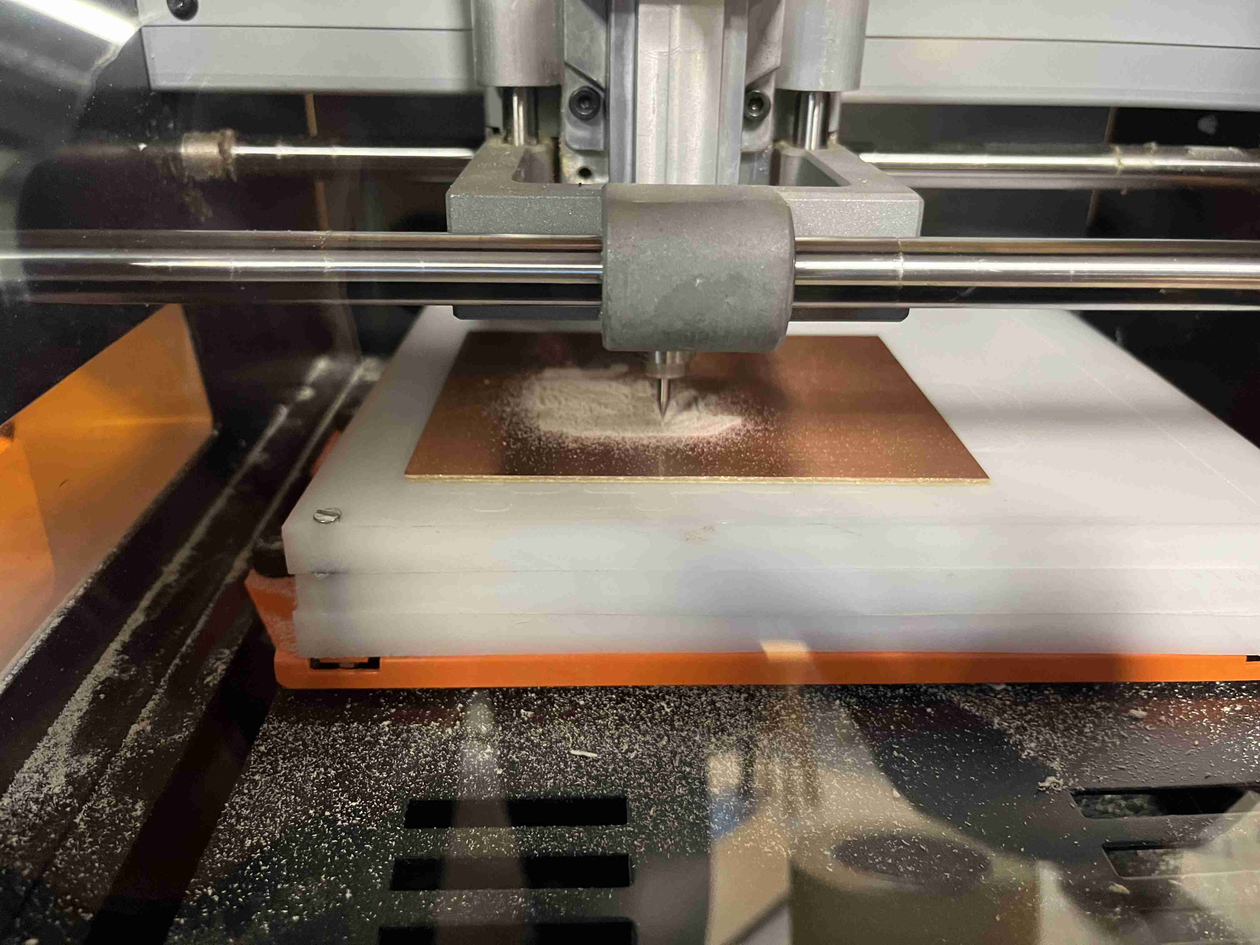
Milling
To prepare my milling, I used mods again. If you'd like more information on the next steps, you can refer to our week of Electronic production. I used mods again to edit my rml file. During the week of electronic production, we had opened the mill 2D program, during this week I used the mill 2D PCB program. We can then enter our SVG image and the various milling parameters. It's important to remember to reverse when you import the traces so that it doesn't cut the traces but cuts around them.
| Passage | Tool diameter | Cuth depth | Max depth | Offset stepover | Speed |
|---|---|---|---|---|---|
| Traces | 0.4mm | 0.1mm | 0.1mm | 5 | 1.5mm/s |
| Interior | 1mm | 0.4mm | 1.8mm | 2 | 1.5mm/s |
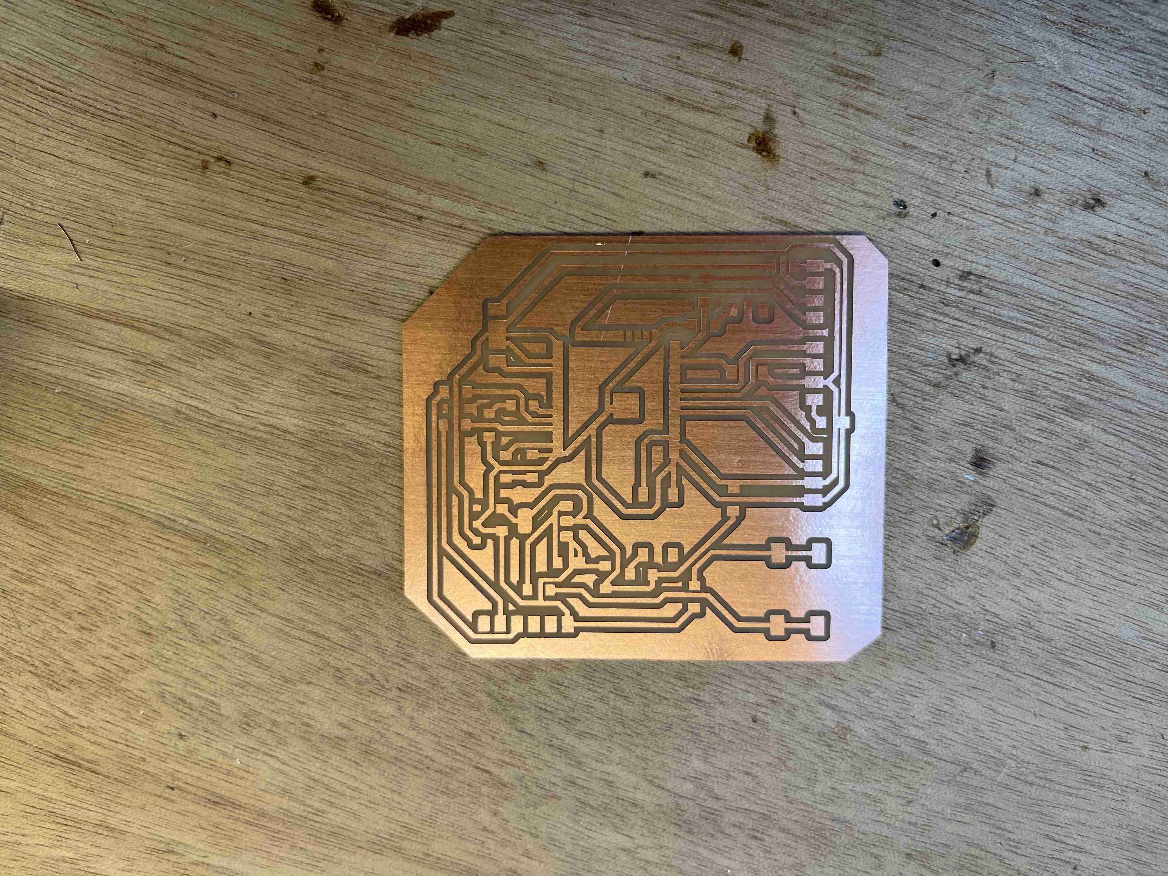
You'll notice that I made two passes to cut my outline, which isn't logical as the diameter of my milling cutter corresponds to the diameter of my outline. I didn't take the time to find out what the problem was and simply made two passes, which doubles the milling time but gives a more satisfactory result. If I'd only left one pass, the milling cutter would have zigzagged and not followed a straight trajectory, which I imagine would have resulted in a poor quality finish. Once the file was ready, I could move on to milling with the Rolland SRM 20. It's also important to reverse the selection when preparing the file, as shown below.
If you want to reproduce this circuit, you will find the different files at the end of the page.
Soldering
Once I'd finished milling, I realised that I'd missed. To do my milling I chose to use a 0.4mm milling cutter, but the distance between the pins on the ESP32-WROOM-32UE is smaller than the diameter of my milling cutter, which meant that the latter didn't mill between the pins. To solve this problem I had to use the ultrasonic cutter again to cut between the pieces of copper that shouldn't have been connected. Once I'd finished re-cutting my tracks, I used the contact tester function on my multimeter to check that I'd done the operation correctly and that there were no connections where there shouldn't be any.
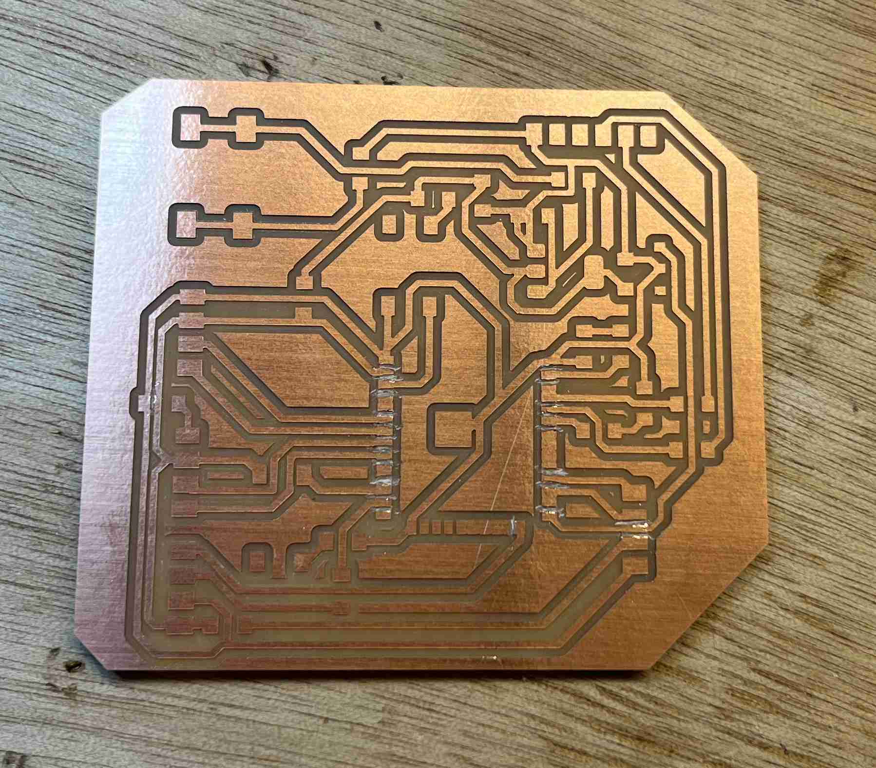
Once all these steps had been completed, I was able to solder all my components onto the circuit.
Here is the list of components I used to make this circuit
| Component | Number |
|---|---|
| ESP32-WROOM-32UE-N4 | 1 |
| CONN JACK R/A SMT 5.5X2.1MM | 1 |
| button | 2 |
| interruptor | 1 |
| capacitor 1UF | 2 |
| capacitor 10UF | 1 |
| Pinheader femaleX4 | 4 |
| Pinheader malex6 | 1 |
| Regulator | 1 |
| Resistor 500 Ohm | 2 |
| Resistor 10K Ohm | 2 |
| Resistor 0 Ohm (Jumper) | 8 |
| Led green | 1 |
| Led red | 1 |
Testing
I now have a ready-to-use printed circuit board. It is not easy to upload a code on it, when you have few skills in electronics. I first wanted to use my Quentorres to televise my code on the esp32 but I couldn't manage to put the UF2 firmware on it to use it as a programmer. So I used a programmer made for this purpose that I can connect to my card by simply connecting the GND and RX terminals to the TX.
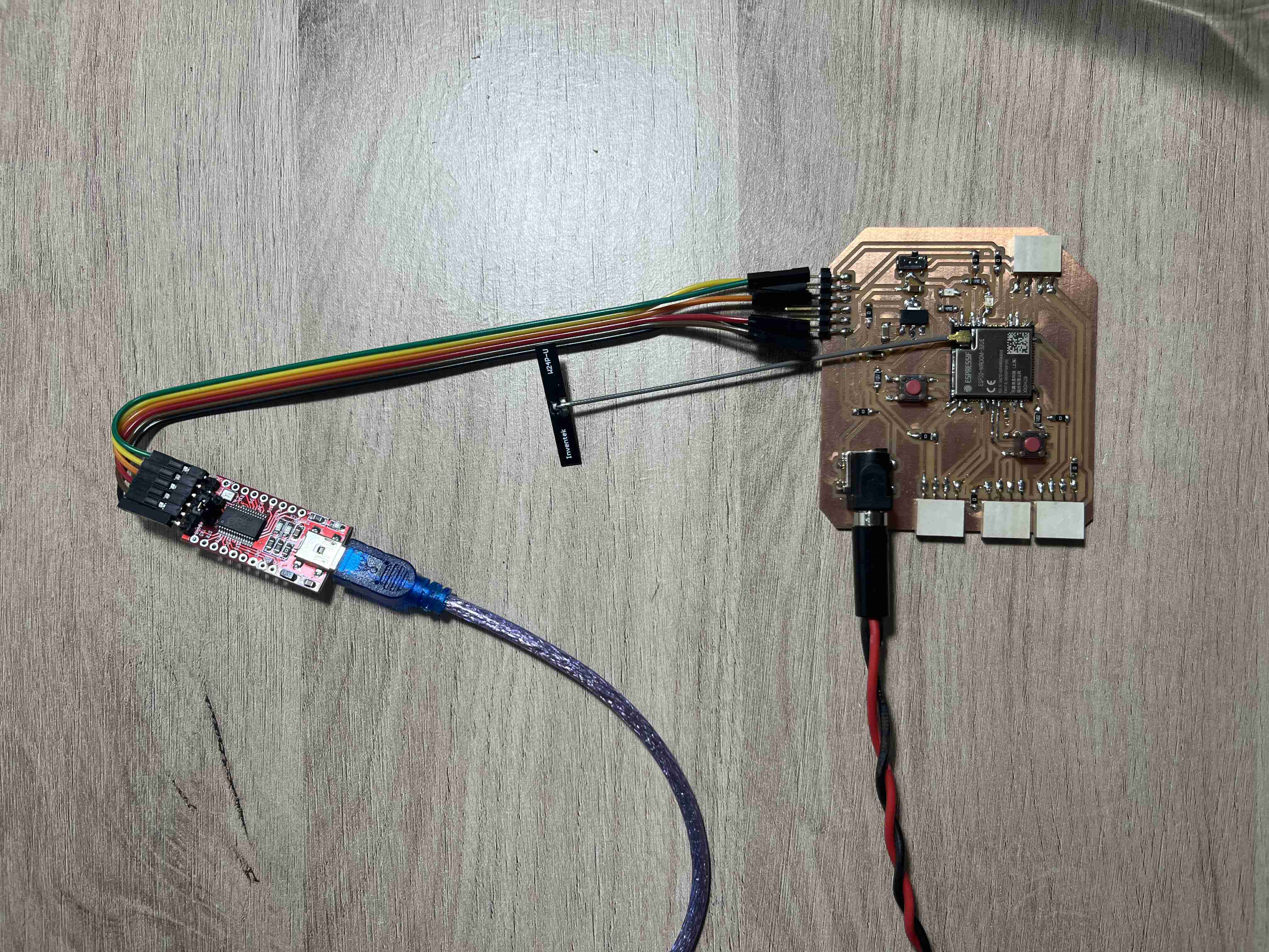
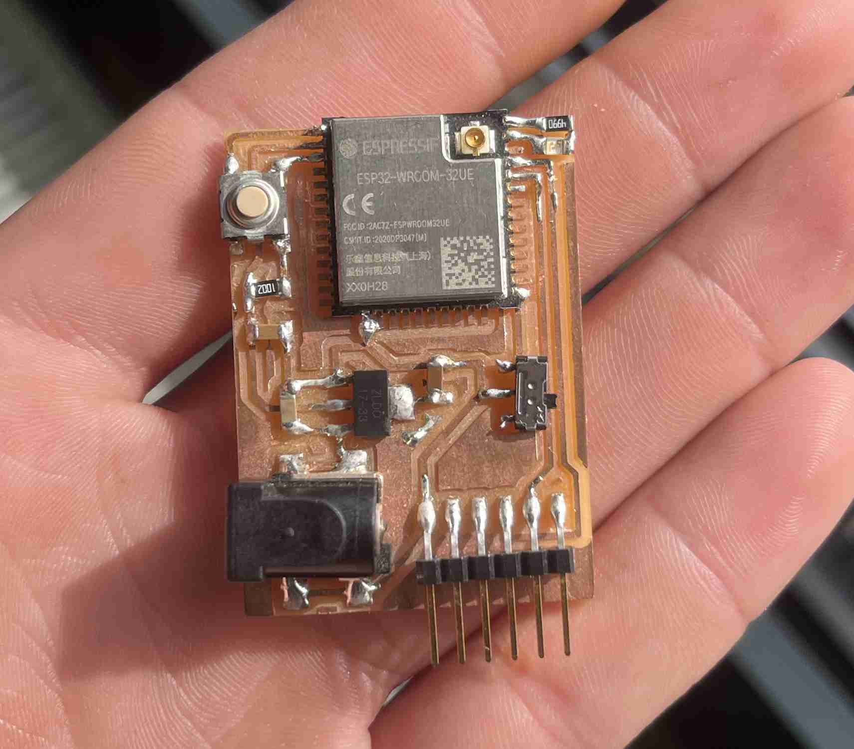
Before even testing our circuit, it is very important to remember to connect an antenna to its location, otherwise the circuit will be burnt out.
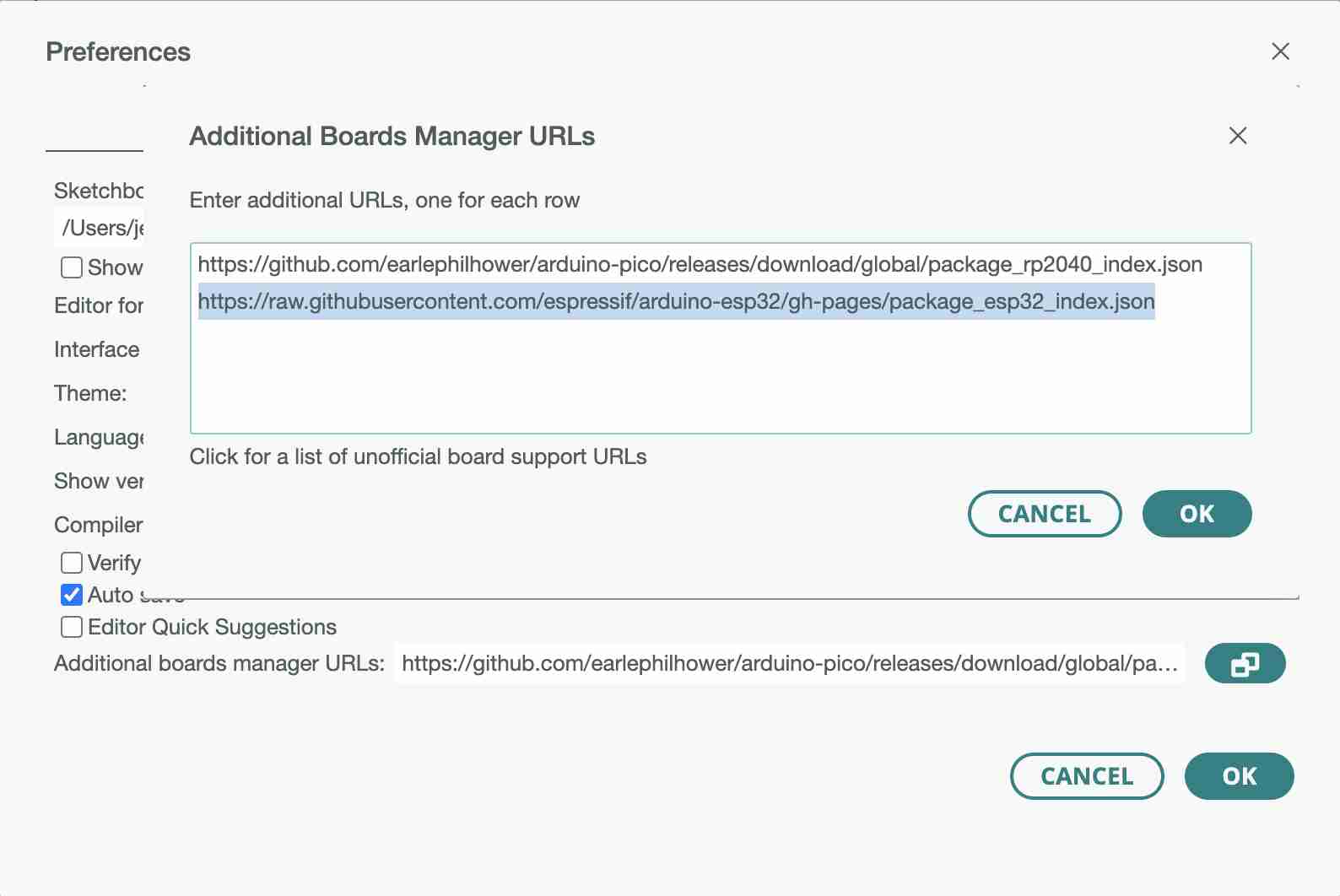
Once you are connected to the programmer, you can open the Arduino IDE and go to the preferences. In the additional board manager, we'll add this link https://raw.githubusercontent.com/espressif/arduino-esp32/gh-pages/package_esp32_index.json which refers to the library for using ESP32.
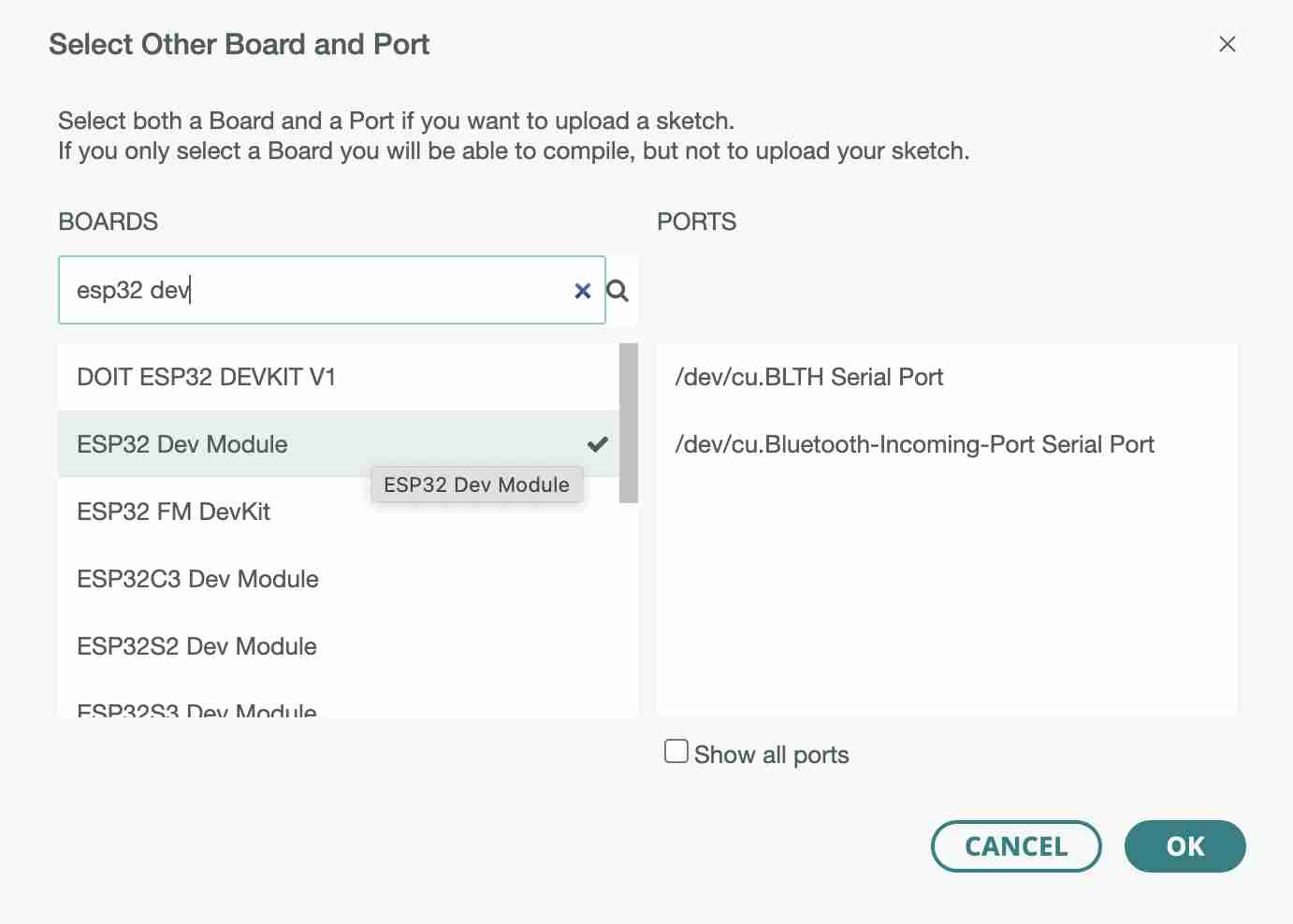
In the cards we're going to use, we'll select the ESP32 Dev Module which corresponds to our microcontroller
You can then create a program to upload. In my case, I chose to create a blink to test my two LEDs by making them work alternately. You can find the code here
// the setup function runs once when you press reset or power the board
void setup() {
  // initialize digital pin LED_BUILTIN as an output.
  pinMode(23, OUTPUT);//Led red
  pinMode(21, OUTPUT);//Led green

}

// the loop function runs over and over again forever
void loop() {
  digitalWrite(23, HIGH); // turn the LED on
  digitalWrite(21, LOW);  // turn the LED off
  delay(500);                      // wait for a half second
  digitalWrite(23, LOW);    // turn the LED off
  digitalWrite(21, HIGH);   // turn the LED on
  delay(500);                      // wait for a half second
}
As far as uploading is concerned, the process is more complex than with a simple arduino, for example. First of all, the switch has to be lifted to be in download mode. You can then test whether there is a connection by opening the serial monitor. You need to pay attention to the baud rate, which is different from an arduino and is not 9600 but 115 200. If you don't change it, what is displayed on the monitor will be inconsistent. If you press the button and you get the message below, the microcontroller is ready for uploading. and you can upload.


Once the code has been successfully uploaded, you can turn the switch down again and press the button, and the code will run.
I made a major mistake when designing this circuit. I had designed it so that it could power two motor drivers as well as a gps module and an LCD screen. However, I've connected one of my drivers to pins that can't do PWM, so the circuit can't send PWM to the driver and when I try the two motors I'll have to solder wires to connect my driver to a pin that does PWM.