Week2. Computer aided design
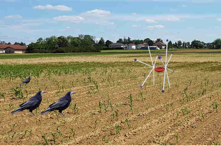
Hero shoot
This second week's topic is computer design, so we'll be looking at the different types of creations that can be made with a computer, firstly in 2D with vector and raster software, and secondly in 3D with animations and simulations.
The week began with workshops given by our instructor to familiarise us with different software, so we had a workshop with presentations on Inkscape(2D), Fusion 360(3D) and openSCAD(3D). I went on to use two of these programs, but I wasn't that interested in openSCAD because it's not necessarily easy to use and I didn't find it much more interesting than Fusion 360.
3D Modelling
To model in 3D, I chose to use Autodesk's Fusion 360 software. I've already modelled and printed in 3D before and it's already the software I've been using. It's pretty easy to use and offers a large number of functions. To work on the 3D modelling, I chose to model a first version of my final project, which is just an idea and will probably be quite different from the final version.
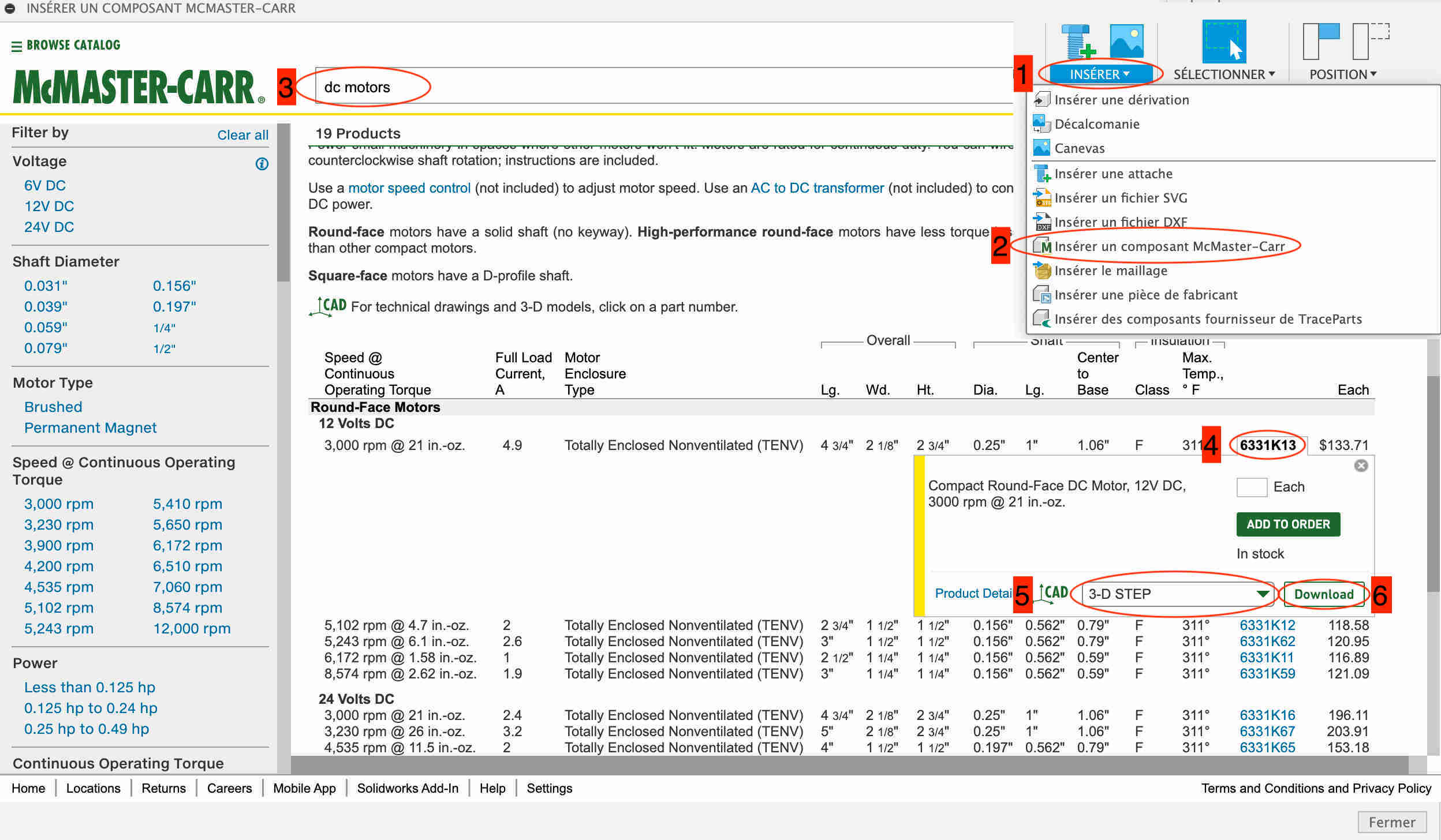
To start my modelling, I based myself on the only elements that I wasn't going to model myself, the electric motors. I used the McMaster-Carr library to get them. It's quite simple, just click on the insert icon at the top right, then click on insert a component from McMaster-Carr. Then look for the component you want, in my case a dc motor. Then select the component you want, taking care not to select the 3D-STEP format before downloading it. The desired component normally appears in our design.
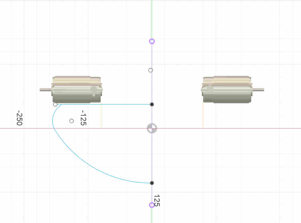
Once I'd positioned my two electric motors, I made a sketch to create the base of the robot, created the shape I wanted on one half and then made a revolution around the Z axis to create my circular shape.
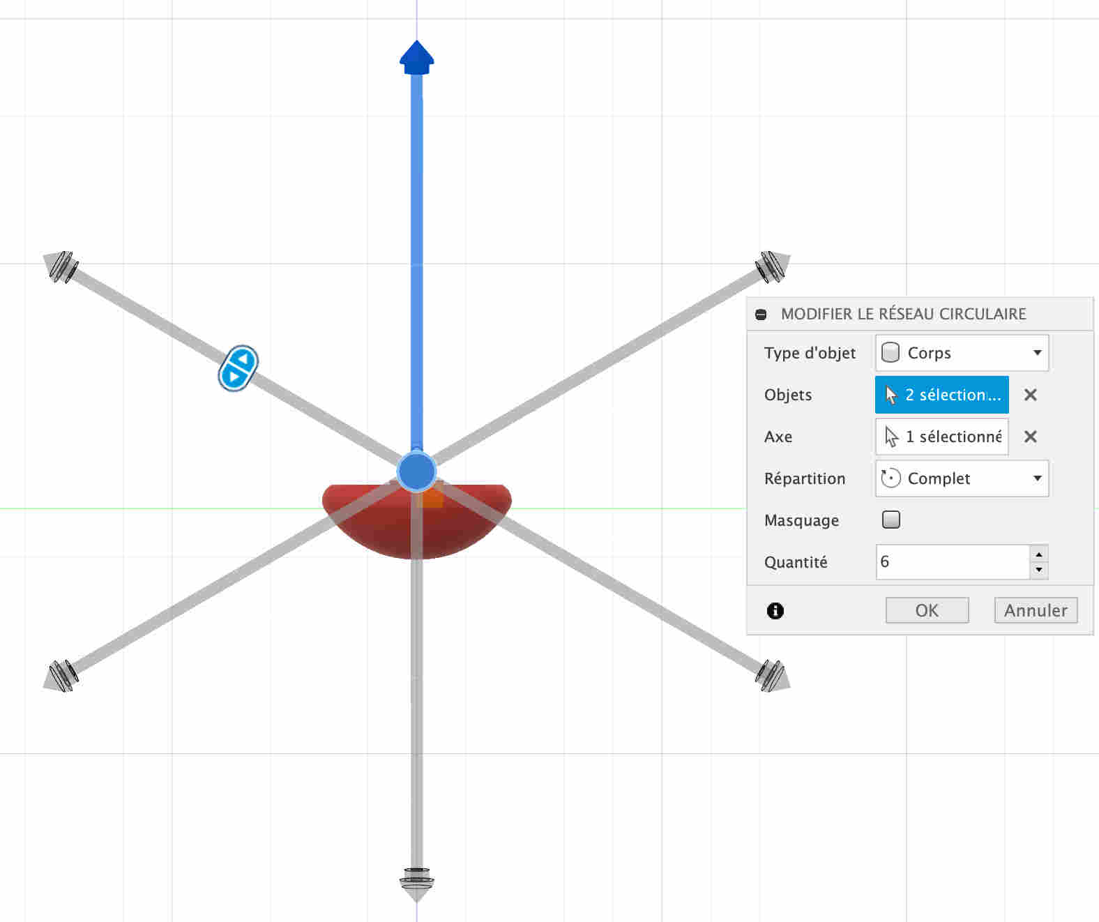
I then made other sketches that I extruded to make the elements of my robot, namely the motor supports and the wheels. As these are wheels with bars, I made a foot and then used the network function to multiply it around the axis of the wheels.
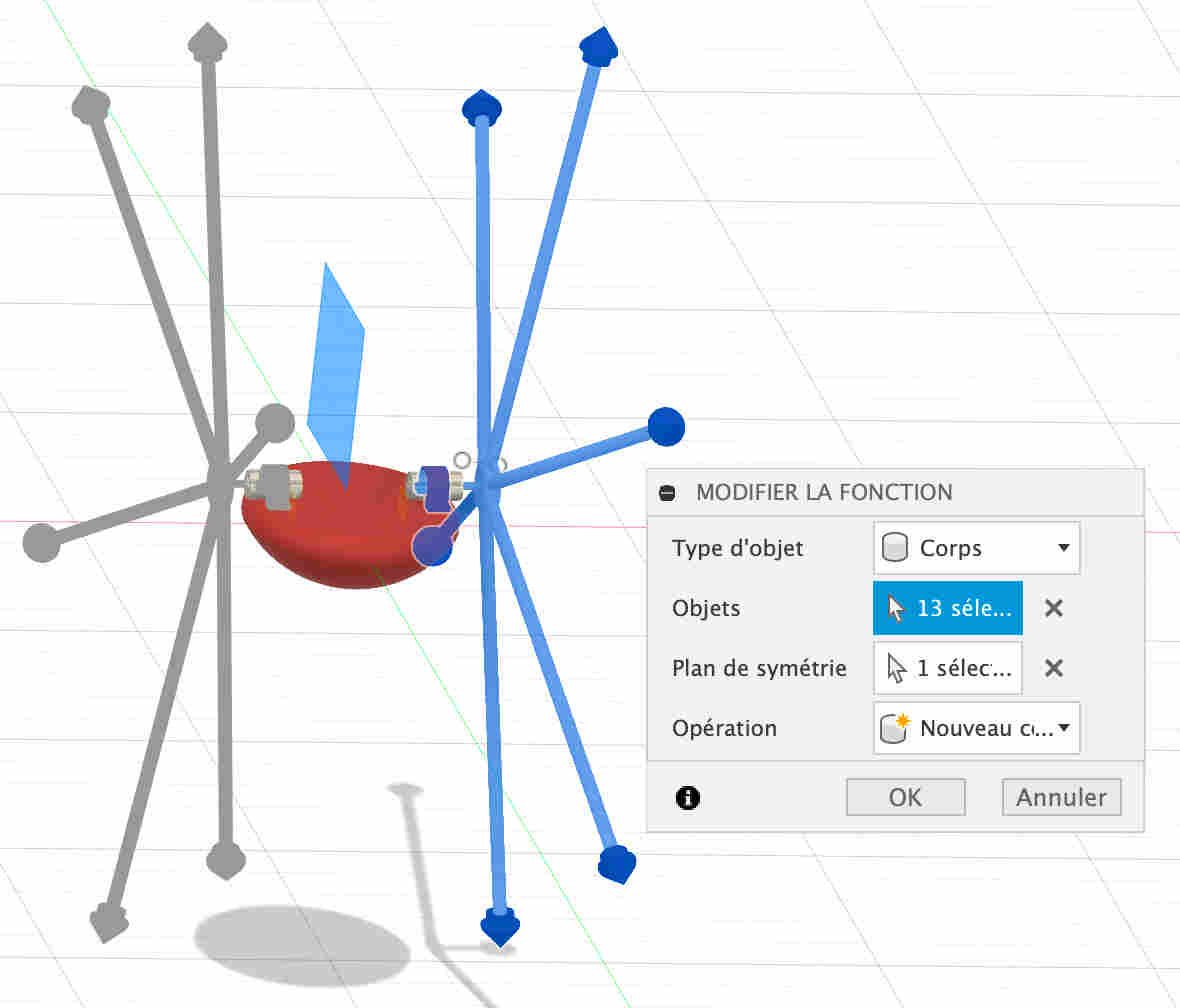
In order to do the same thing on the other side, I had to make a symmetry of these bodies in relation to the Z axis.
Parametric creation
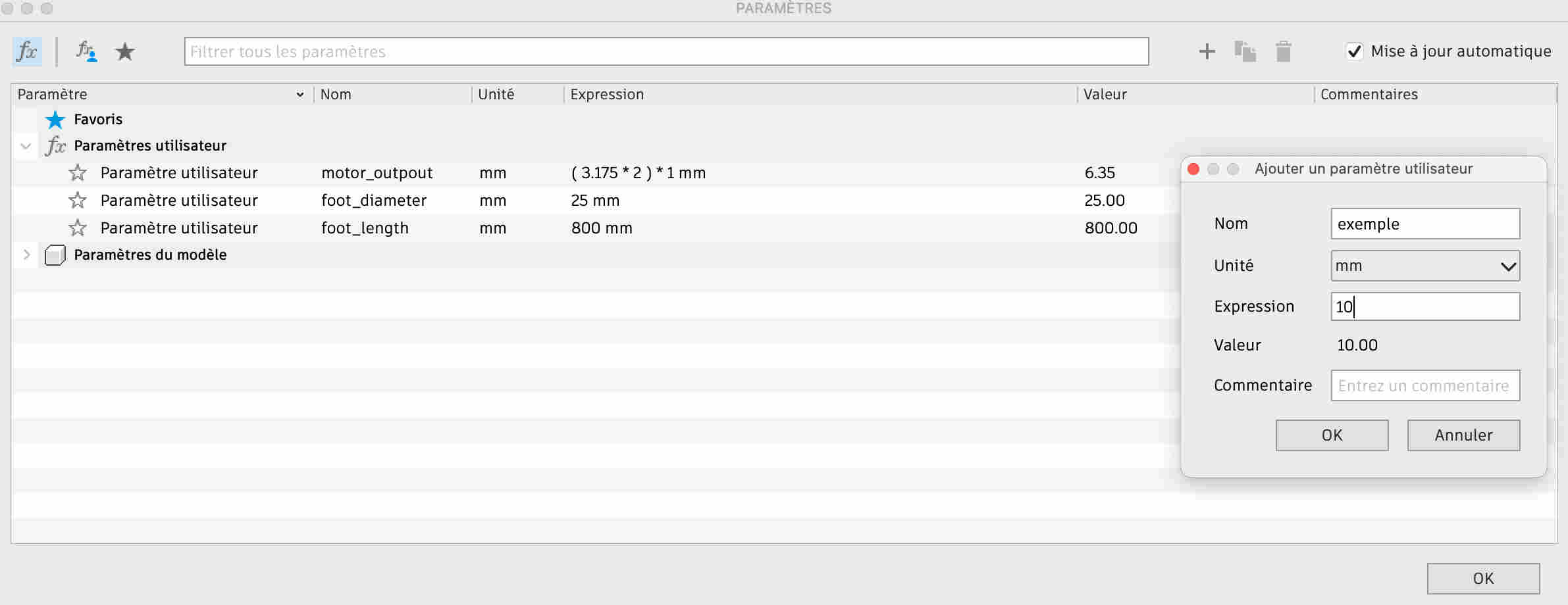
In order to be able to change the values of certain elements of my design, I was able to use parameters that I can still change in order to modify my design. To create parameters, simply go to the edit tab at the top and select the edit parameters option. By clicking on the + you can create a new parameter by entering the name you want to give it and its value. Then, when you want to create a new object, all you have to do is enter the parameter name and change the value. I've only created 3 parameters, the size of the motor output where my wheel fits, the diameter of the bars and their length. I'm very sorry I didn't create more, because when I want to go back, a lot of bodies change place. I should have created one to change the angle of my feet in relation to the support, that would have allowed me to see how the robot would look with different angles.
Creating links
I also made some links so that I could rotate my wheels. To do this I first went to the assemble menu, where I selected the create tool. You then select the two linked faces separately and specify the movement, in my case a revolution. I had a lot of trouble making my wheels turn because I was simply trying to make my motor output shaft coincide with the part that fits on the end, so it was only the motor that was rotating on itself. I had to create a component that included all the components of my wheel to make it work.
Change of materials
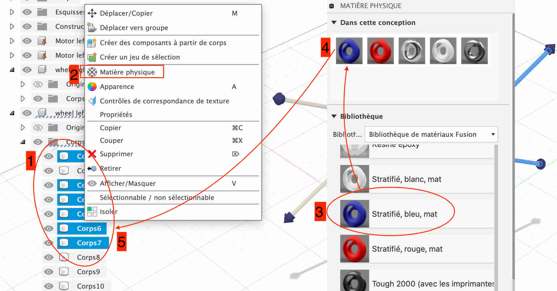
To make my object more realistic and more attractive, I chose to change the materials to give it a different appearance. It's very easy to do, just select the body whose material you want to change, right-click and choose physical material. You then arrive on a page with a multitude of materials, just click on the ones you want at the top of the design materials, and then simply drag the materials onto the bodies you've selected. In my case I've only used plastic because it will be the main component. As for the colour, I wanted a different one for the body of the robot, for the bars and for the spikes, so I chose blue, white and red, the colours of the French flag.
Later, when I'd done my vector creation on Inkscape, I had fun importing it into my design using the insert function, then inserting an svg. Then all you have to do is move the model around and enlarge it as you like. I had a hard time getting this step right because there were two lines that barely touched, which made it look as if the shape wasn't closed. I had to find where the "hole" was in my sketch in order to put a sketch line there. I then extruded the sketch to make it more visible.
Creating a rendering
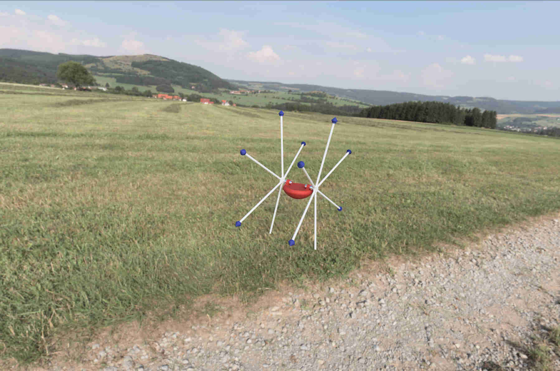
To make my design more realistic, I did a render to show what it might look like. To do this I went to the Fusion 360 render menu. In the configuration tab, I changed the scene settings. I chose to change the environment by taking the field environment and then I adjusted the various parameters to make the render as realistic as possible. I then went to the render function and it suggested various adaptations before editing the final render. All that's left to do is run it and download it.
Make an animation
In order to make an animation, I first wanted to use the menu dedicated solely to 360° fusion animations, but there must have been some problem with my design, but I wasn't able to make it move, or else it was the whole robot that was rotating on itself. So I chose to stay in the design menu and activate the movement link for my two wheels. I took the screenshot using the functions on my computer by simply entering Control+Shift+5.
FFMPEG
To compress my videos, I've chosen to use FFMPEG software. To install it, all you have to do (if you've already installed hombrew like me) is enter the terminal:
brew install ffmpeg
You will then see all the different packages being downloaded. Once the installation is complete, you can call the user by simply entering, for download and use ffmpeg I sue also the help of this video
ffmpeg
You then need to go to the file containing our video using the cd function (as you did for git last week) and find the folder containing our video and enter one of the lines suggested in Neil's course according to our needs, taking care to set video input to the one you want to transform and outpout to the new one.
Then I had problems using ffmpeg on my Macbook. When I compressed the videos, they changed quality, which made them unreadable on my video player and on my website. My instructor Luc helped me solve the problem by adding this command: -pix_fmt yuv420p to my usual code and it worked. So here's the command I use most often, without audio, because in many cases it's useless:
ffmpeg -i input_video -vcodec libx264 -b:v 1000k -vf scale=-2:1080 -pix_fmt yuv420p -an output_video.mp4
Final creation
You can get the f3d file here
Vector design
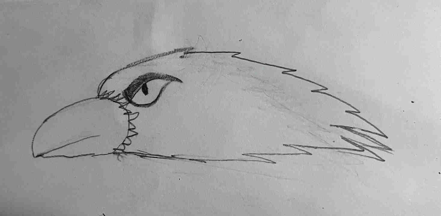
In order to take an interest in 2D vector design, I chose to use Inkscape for a number of reasons. Firstly, because it's open source, so it's accessible to everyone; secondly, because it was introduced to us by our instructor and it's used a lot at Agrilab, so I'd have help if I had any problems with it; and thirdly, because I'd used it before, so I was already familiar with the software. In order to use this software, I wanted to create a logo with a raven, in keeping with the theme of my final project. Before moving on to vector creation, I chose to try drawing it by hand as you can see below.
Once I'd finished the design, I took a photo of it and sent it via Airdrop to my computer to preserve maximum quality. However, even once the photo had been converted to PNG (the photo format on the iPhone is HEIC), I couldn't open it with Inkscape, so I had to take a screenshot of the photo on my computer to be able to open it. To do this, just go to File at the top, then Import and finally choose your image.
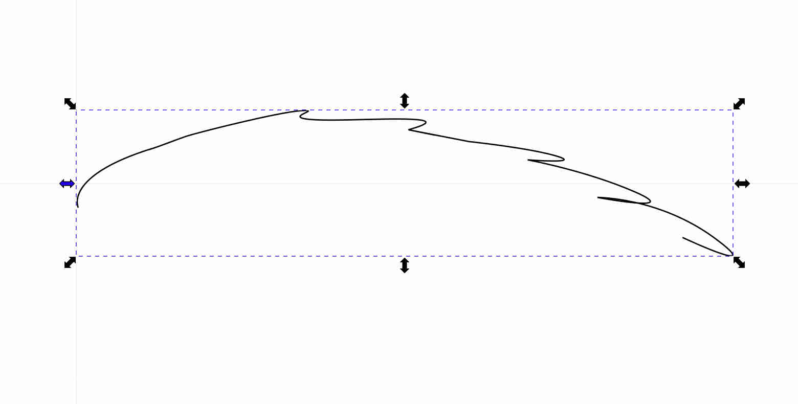
I then selected the Bézier curve tool to crop my design. Once I'd done that, all I had to do was hide the original image and use the selection tool to move the different points to get the prettiest rendering possible.
Once I'd finished the various designs, I went to the path tab to select the combine function to create a single design.
I then created a copy of my design, keeping only the top part and removing the rest. I stretched it so that it was slightly larger than the rest, then combined the two drawings again so that only one remained.
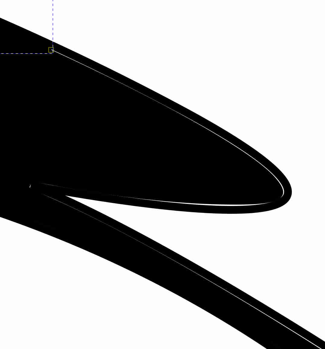
I then moved on to colouring, using the fill in the bounded area function and putting black in a certain place. I still had spaces where there was no colour, so I used the freehand line drawing function to fill them in.
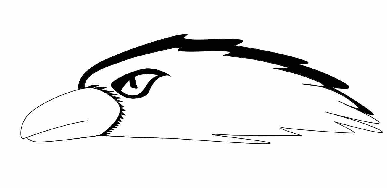
And this is the final sketch, with all the modifications. You can find the original file by clicking here
Raster design
To create raster images, I chose to use the Gimp software, because it's open source and I'd already used it. It's a raster image editor in the same style as Photoshop, but it's free. As I didn't have much inspiration, I continued to work on my final project. I chose to make a more realistic representation of the rendering given by fusion 360 earlier.
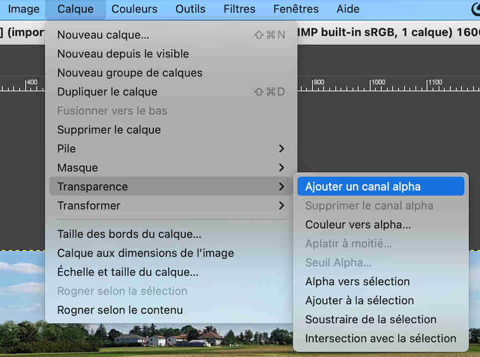
To do this I started by opening the png image of the fusion render with Gimp. Before starting anything, you need to go to the layer>transparency>add alpha channel tab, which is important because it meant I had to start cropping the whole robot twice, I understood my mistake thanks to this video.
Once you've done this, you can use the foreground extraction tool or the path tool to crop what you're interested in, in my case either the robot or the raven. You then need to take the time to select everything carefully by going around each edge and once the selection is complete, simply press enter. Now go to the selection tab and select invert (or
Then simply open. The image to which you want to add this element, in my case the image I used as the banner for my final project. All you have to do is select the previously saved elements, which should be in the frame on the right, and add them to our image. In my case I used the rotation tool as well as the scaling tool to better position the elements I had just added to my image. I copied (