# JUNE
# Fab Academy 2025: Celebrating Innovation, Graduation, and a Global Community
After months of relentless learning, building, documenting, and pushing the boundaries of digital fabrication, Fab Academy 2025 has officially wrapped up its final presentations. Across five days, students from around the world showcased their final projects—each one a unique embodiment of technical mastery, personal creativity, and the power of the global Fab Lab network.
# 🌍 A Global Effort in Numbers
This year’s edition was one of the most ambitious and diverse to date:
188 students
58 labs across 35+ countries
130 final projects presented
111 graduates (and counting!)
From interactive art to practical robotics, environmental sensors to education-focused devices, Fab Academy 2025 projects reflected the variety of interests, contexts, and challenges that students are addressing through digital fabrication.
# 🌟 Highlights from the Final Presentations
Here are just a few standout projects from this year's talented graduates:
Lumi by Noel Saji – A quirky robot-TV that “wakes up” when nobody’s watching. It plays animations, walks like a toy, and switches to normal TV mode when it detects a person nearby.
Chocobot by Roshan Subba – A fun and educational robot designed to teach children the importance of recycling and cleanliness, using interaction and storytelling.
GlowSense by Ancy Roshan – A pair of lamps that communicate wirelessly, glowing to signal presence and connection between distant users.
Cultural Memory Globe by Shoko Kudomi – A device that plays video and light animations reflecting the culture and climate of countries around the world.
Bending Bench by Pepe Vazquez – An interactive bench that visualizes structural stress in real time, making engineering principles tangible and fun.
Nap Pod by Tshering Dorji – A personal cocoon for power naps, complete with mood lighting and sound controls via capacitive touch.
From intelligent lighting systems to modular learning kits, underwater robotics to immersive installations—this year's projects were as diverse as they were impactful.
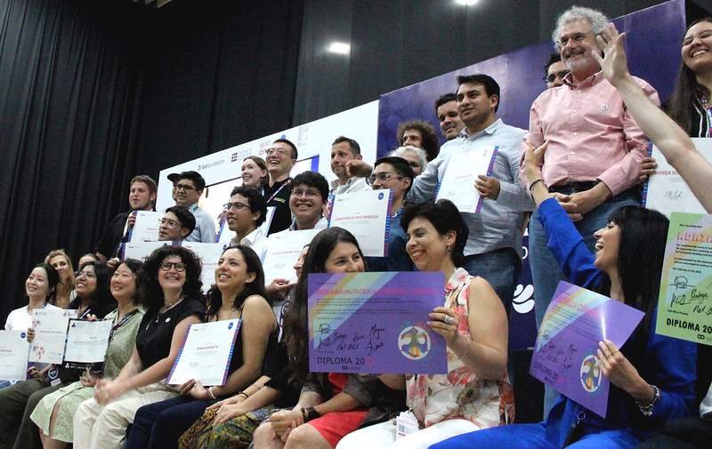
# 🎉 Graduation at FAB25 in Brno
We now look ahead to July 7, when we’ll celebrate our graduates at the Fab Academy 2025 Graduation Ceremony, hosted during FAB25 in Brno, Czech Republic. Whether you join us in person or online, it will be a moment to honor the hard work, innovation, and global collaboration that define Fab Academy.
# 🚀 What’s Next? Pre-Register for Fab Academy 2026
Are you ready to build your own innovation journey? 🌱 Pre-registration for Fab Academy 2026 is now open!
👉 Click here to pre-register (opens new window) and become part of a global community of makers, learners, and change-makers.
# Congratulations to the Class of 2025!
Thank you to the instructors, mentors, evaluators, and all the Fab Labs who made this year possible. See you at graduation—and in the next cycle of Fab Academy!
# MAY
# Fab Academy 2025: The Final Stretch Begins
As we enter the final stretch of Fab Academy 2025, students across the globe are integrating everything they’ve learned—preparing not only for final presentations but also for the potential to turn their ideas into lasting innovations. The fourth month has been a whirlwind of technical deep-dives, inspiring recitations, and impressive project progress. Here’s a recap of everything that unfolded.
# Wildcard Week: Exploring the Unexpected
Wildcard Week offered students the opportunity to dive into tools and techniques beyond the standard Fab Academy curriculum—encouraging creativity, experimentation, and hands-on exploration in new domains. From electroplating to industrial cutting, students embraced the chance to expand their skill sets in unexpected directions. Jadelyn from Wheaton (opens new window) explored electroplating, experimenting with metallic finishes to enhance her projects. David Chan from Chaihuo (opens new window) built and tested a custom UV printer, showcasing how electronics and mechanics can be combined to create powerful digital fabrication tools. Tsheyang Palki Tshewang from DGI (opens new window) used a Zund cutter to transform cardboard into elegant, precise creations, blending craftsmanship with industrial precision. Meanwhile, Pradeep from Vigyan Ashram (opens new window) explored both embroidery and plasma cutting, bridging textile arts with metal fabrication. Wildcard Week continues to be a vibrant space for bold experimentation, turning curiosity into real capability.
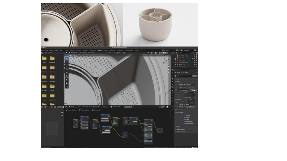
# 🛠️ Final Project Development in Full Swing
Final projects at Fab Academy are pushing the boundaries of creativity and technical skill, with students developing everything from modular lighting systems to robotic pets and educational tools. Richard is designing a sleek PCB-integrated magnetic bike light, while Forrest is creating an interactive labyrinth that uses LED strips and accelerometers to respond to motion. Sujith is focused on Bluetooth connectivity for a child-tracking device, and Roshan’s “Chocobot” is a playful robot designed to teach kids about recycling. Namita is building a modular gamepad that doubles as a Minesweeper interface, and Jeremy is developing a photo effects machine inspired by his product design experience, and Oscar is engineering a smart bartender powered by solenoids and microcontrollers. Throughout this phase, Neil and the Fab Academy team have consistently emphasized the value of documentation, precision, and thoughtful design—reminding students that success lies in building well-integrated, thoroughly tested systems.
# Fab Recitations: All In and Start-Ups
This month featured two deeply inspiring recitations:
# 🌍 Fab All-In (opens new window)
A session that showcased the power of inclusive innovation—featuring stories of Fab Labs solving real-world challenges in rural communities, healthcare, and education. The message was clear: Fab Labs are for everyone, and they can be tools for systemic change.
# 🚀 Fab Academy Start-Ups (opens new window)
Could your Fab Academy final project become your first startup? For many alumni, it already has. In this recitation, students learned how to turn prototypes into products, navigate funding options, and build meaningful ventures rooted in digital fabrication. Topics included MVPs, business models, and the power of open-source ecosystems.
# Final Systems and Integration: Pulling It All Together
The final phase of Fab Academy challenges students to fully integrate their systems, combining embedded electronics, mechanical fabrication, data interfaces and visualization, input and output devices, wireless communication, and user experience design. This stage is where everything comes together. Class lectures have emphasized the importance of design for disassembly, rigorous documentation standards, safety, and performance testing. Beyond technical execution, Neil urged students to think critically about usability—encouraging them to not only build systems that work, but ones that feel intuitive and meaningful to use.
# 🎯 What’s Next?
We’ve entered the final stretch. Students are preparing for their final presentations, project documentation, and video submissions. They’ll showcase their journey through digital fabrication—bringing together everything from CAD to CNC, code to community impact.
It’s the moment where prototypes become products, and ideas become innovations.
# ✨ Pre-registration for Fab Academy 2026 is Now Open!
Ready to begin your own digital fabrication journey?
Click here to pre-register for Fab Academy 2026 and be part of a global network of learners, makers, and innovators.
# APRIL
# Fab Academy 2025 Three months in– 55+ Machines, Boundless Creativity, and Engineering Mastery
Month three of Fab Academy 2025 has proven to be one of the most ambitious and inspiring yet. As students progressed past the midpoint of the program, they were challenged to collaboratively design, build, and document machines in just one week—and they delivered with over 55 functioning machines built in Fab Labs around the world.
From CNC wire benders and robotic arms to rotocasting machines and Zen garden plotters, this global machine-building sprint has showcased the full power of the Fab ecosystem: distributed collaboration, open-source ingenuity, and hands-on learning and a tangible move towards the 2.0 era, characterized by increasingly sophisticated tools, specialized applications, and the ability to tackle more complex challenges across diverse fields.
# 🛠️ Machine Week: A Global Engineering Feat
The annual Machine Building Assignment ignited a powerful display of Fab Academy students' collaborative talent and inventive drive. Spanning continents, their efforts culminated in the successful fabrication of more than 55 machines in labs around the globe. Within a single week, teams navigated the complexities of mechanical design, electronics integration, motion control, and user interface development. The resulting creations, ranging from imaginative concepts to practical tools, underscored their technical mastery and thoughtful design process.
# 🌍 Machine Week Highlights:
Here are just a few of the machines that came to life:
🔹 “Plan B” Onigiri Maker – Kamakura
(opens new window)🔹 Automated Radio Telescope Mount – DGI
(opens new window)🔹 XY Plotter – ESAN
(opens new window)🔹 Rotocasting Machine – “Ice Cream Sandwich” – Creative Spark
(opens new window)🔹 Ball Catchers – Aalto + Hisar
(opens new window)🔹 ScanLab X1 – Bahrain
(opens new window)🔹 Spider Robot – Wheaton
(opens new window)🔹 Coin Sorter – Singapore
(opens new window)🔹 Five-Axis Robot Arm – Rwanda
(opens new window)🔹 Zen Garden Plotter – Kannai (opens new window)
Each project was accompanied by a detailed video demo and full documentation—capturing not just the end result but the process, challenges, and learning along the way.
# 🔧 Deep Dive into Machine Design
Leading up to Machine Week, Fab Academy students delved into foundational concepts encompassing mechanisms and motion, structural design principles utilizing elements like aluminum extrusions and self-aligning joints, actuation and control systems involving stepper motors and PID control, and automation and interfaces achieved through software integration with Python, JavaScript, and MQTT. Organized into collaborative teams, students strategically divided tasks across the critical domains of mechanics, electronics, firmware, and UI/UX, providing them with a comprehensive full-stack perspective on the intricate process of building functional hardware systems.
# 🧪 Molding and Casting: Manufacturing with Form and Function
In parallel with their machine-building endeavors, Fab Academy students immersed themselves in the essential manufacturing technique of molding and casting. This exploration involved mastering the creation of both rigid and flexible molds, working with a diverse range of materials including resins, silicones, and even metals, with a strong emphasis placed on achieving high-quality surface finishes and adhering to rigorous safety protocols. Key aspects of the learning included understanding precise mixing ratios and curing times, implementing techniques to avoid air bubbles and ensure smooth casts, and utilizing both 3D-printed and CNC-milled molds as versatile fabrication methods.
# ✨ Featured Molding Projects:
Injection Molding – Mkhitar Evoyan (Armenia) (opens new window)
SLA vs CNC Mold Making – David Fernandez (León) (opens new window)
# 💻 Interface & Application Programming
In the concluding phase of the month, Fab Academy students focused on bridging the physical and digital realms by exploring the creation of software interfaces for their hardware projects. This involved delving into a range of programming languages such as C, Python, and JavaScript, alongside visual programming tools like Node-RED, and mastering web development technologies including HTML5, Canvas, SVG, WebGL, and Three.js to build diverse user interfaces like terminals, web forms, and dashboards. Furthermore, they gained experience in data visualization using tools like matplotlib, Jupyter, and D3.js, and critically examined the capabilities and limitations of integrating AI tools within their code, ultimately empowering them to transform their machines into intelligent and interactive systems.
# 🌀 Beyond the Lab: Fab Ecosystem & Community
A special recitation covered the broader Fab Ecosystem, including the Fab Foundation, Fab City initiatives, and the upcoming Fab25 global event in Prague. This gave students a vision of how their projects contribute to a global movement of distributed innovation. Check it out HERE (opens new window)
# 🌟 What’s Next?
With Machine Week and interface programming behind them, students now enter the final stretch of Fab Academy 2025. The focus shifts toward developing their final projects—where all the skills they’ve built over the past months come together.
This is where prototypes evolve into fully functional, meaningful innovations—and students take ownership of projects that represent their personal goals, passions, and creativity.
🔗 Got inspired and want to join the Fab Academy journey? Pre-Register here (opens new window)
# MARCH
# Fab Academy 2025: Month 2 – Innovating, Building, and Exploring New Frontiers
The second month of Fab Academy 2025 has been packed with hands-on projects, advanced techniques, and inspiring discussions. From building furniture-sized projects with CNC machines to diving into cutting-edge quantum optics and electronics production, our students continue to push the boundaries of digital fabrication. Let's take a look at the highlights from this exciting month!
# 🪚 Recap of the Month
The month began with an in-depth exploration of CNC machining, an essential skill for fabricating large, functional structures. Under Neil’s guidance, students worked with full sheets of plywood, creating furniture-sized prototypes while mastering different aspects of the machining process. They were introduced to various types of CNC machines, ranging from small handheld routers to large industrial systems, and learned the importance of tool selection—distinguishing between drill bits and end mills to ensure precise cuts. Advanced machining techniques, such as trochoidal milling and chip load management, were discussed to optimize efficiency, while a strong emphasis was placed on safety, proper fixturing, and precision.
The focus then shifted to electronics, with students diving into printed circuit board (PCB) production—an essential component of functional prototyping. Neil introduced various PCB production methods, including milling, etching, and vinyl cutting, and showcased advanced machines like the xTool F1 Ultra for PCB engraving. The module also covered material choices, comparing FR1 and FR4 boards, with a strong emphasis on safe chemical disposal practices. Students refined their precision techniques, using stencils for reflow soldering and mastering intricate hand-soldering methods.
Building on these skills, Neil guided students through an exploration of input devices and sensors, demonstrating how they can be interfaced with microcontrollers to create interactive projects. Students experimented with capacitive sensing for detecting touch and material composition, magnetic field sensing through vector magnetometers for spatial awareness, and gesture recognition using Doppler radar and RGB sensors. Additionally, they explored advanced sensor interfaces by integrating accelerometers, gyroscopes, and light sensors, expanding their capabilities for dynamic and responsive projects.
Student Highlights:
Shintaro Ito (Kannai) (opens new window) – Extendable Table
Evelyn Cuadrado (Lima) (opens new window) – Cupboard
Mkhitar Evoyan (Armenia) (opens new window) – Foosball Table
Carl Mcateer (Creative Spark) (opens new window) – Awesome Chair
Jhasmin Ayala (ESAN) (opens new window) – Boards Shaped Like Organs
Johannes Andresson (Isafjordur) (opens new window) – 2-Axis Force Sensor
Akash Edamana (Kochi) (opens new window) – Neopixel + Accelerometer
Namita Aravind (Kerala) (opens new window) – Rotary Encoder and Capacitive Sensor
Featured Projects:
Ana Camila Luna (Cuenca) (opens new window) – PCB Laser Engraving
Namita Aravind (Kerala) (opens new window) – Space Invaders Board
Abin Mathew (Kochi) (opens new window) – Vinyl Copper Board
Ofelia Sevilla (Ulima) (opens new window) – Nice Board
# 🎙️ Recitations: New Skills and Perspectives
Fab Academy hosted multiple insightful recitations this month:
Fab 2.0 Portal: Exploring open designs of Fab Lab machines that can be built within a Fab Lab
Quantum and Optics Discussion: How Fab Labs can make optical experiments more accessible
Machine Building and Inputs: Hands-on approaches to integrating sensors with microcontrollers
Catch the recordings here: www.youtube.com/playlist (opens new window)
# 🚀 Looking Ahead: Pushing Innovation Further
As we move into the next phase of Fab Academy 2025, students will focus on output devices, networking, and application programming. The journey thus far has been transformative, and we can't wait to see what comes next!
#FabAcademy #DigitalFabrication #MakerMovement #CNC #QuantumMechanics #Electronics #Innovation #InputDevices
# FEBRUARY 2025
# Fab Academy 2025: A Month of Celebration, Innovation, and Collaboration
In keeping with tradition, Fab Academy 2025 opened with the final presentations of students from the previous class—an opportunity to share, reflect, and celebrate together. The class of 2025 welcomed 183 students from over 50 countries, supported by 55 global nodes. And the 2024 academic cycle concluded with an impressive total of 168 graduating students!
The first month of Fab Academy 2025 was an exciting journey filled with hands-on learning, collaboration, and cutting-edge innovation. Students from around the world engaged in digital fabrication, acquiring proficiency in design tools and extending the limits of their creativity. From setting up repositories and refining CAD skills to exploring AI, 3D printing, and embedded programming, this year’s cohort has accomplished a lot in a short amount of time!
Here are some highlights:
# Kicking Off With Digital Foundations
The first few weeks focused on establishing strong practices for digital documentation and collaboration. Students learned about:
Repo management & Git best practices – Keeping repositories lightweight and efficient for smooth project documentation
Version control with Git – Streamlining workflows with shortcuts and efficient commit strategies
Website creation – Exploring tools like Notion, HTML5 UP templates, and Linux-based development environments
# CAD & Design: From Sketch to Reality
Students took their first deep dive into Computer-Aided Design (CAD), exploring:
2D & 3D modeling using FreeCAD, Fusion 360, OpenSCAD, Blender, and GrasshoppeR
Parametric design for adaptive structures and press-fit kits
Game engines and physics simulations with Unity, Unreal Engine, and Blender
🌟 Featured Projects:
Ana Camila Luna (Cuenca) (opens new window) created 3D models in VR using Gravity Sketch.
Forest Oliphant (Aalto) (opens new window) explored PicoCAD and SolveSpace for 3D modeling.
Pablo Guindos (A Industriosa) (opens new window) designed energy-efficient panels using Grasshopper.
# Computer-Controlled Cutting & Fabrication
The transition from digital design to physical prototyping began with laser cutting, vinyl cutting, and CNC techniques. Students were challenged to create parametric construction kits that could be assembled in multiple ways.
🔥 Featured Projects:
Jeremy Losaw (UNC Charlotte) (opens new window) designed a laser-cut bokeh filter kit.
Evelyn Cuadrado (Lima) (opens new window) experimented with textile vinyl applications.
Leonardo Zamora (Puebla) (opens new window) created a laser-cut roller coaster model.
# 3D Printing & Scanning: Pushing the Boundaries of Digital Fabrication
Students took on the challenge of 3D scanning and printing, exploring various technologies, materials, and design strategies. They learned about:
3D printing processes – SLA, FDM, and binder jetting
Design rules – Avoiding overhangs, optimizing support structures, and using slicing software efficiently
3D scanning techniques – Photogrammetry, structured light scanning, and LiDAR
🛠 Featured Projects:
Elsa Cui (Formshop) (opens new window) used a Goertek VR model full-body scanner for human modeling.
Julian Bassler (HRW Bottrop) (opens new window) designed and printed a chainmail spinning top.
Mihir Shah (Riidl) (opens new window) created an illuminated Batman Light.
Diarmuid Kelly (Creative Spark) (opens new window) explored Reality Composer Pro and parametric plant pots.
Leonardo Zamora (Puebla) (opens new window) designed a 3D-printed lightsaber.
Omar Albalbaki (Techworks) (opens new window) experimented with Robot Operating System (ROS) for 3D scanning.
# Embedded Programming & AI-Powered Making
The class has also delved into electronics, programming, and AI, paving the way for smart and interactive projects. Topics covered:
Introduction to embedded programming using STM32, RP2040, and Pico W
EDA tools like KiCad and Eagle for circuit design
AI-powered fabrication with tools like Stable Diffusion, Midjourney, and TinyML
🔧 Featured Projects:
Jakob Lerch (Ilmenau) (opens new window) explored FAUST for sound processing.
Shintaro Ito (Kannai) (opens new window) used LLMs in Japanese to learn electronics.
Daniel Perez (Puebla) (opens new window) leveraged AI for automated coding and design.
# Recitations: Deep Dives into Key Topics
Throughout the first month, students also participated in expert recitations, gaining insights into advanced tools and best practices:
Mastering Git for digital collaboration with Julian Gallimore – Understanding the backbone of efficient project management
Debugging & problem solving with Nicolas De Coster and Henk Buursen – Learning troubleshooting techniques for electronics
Exploring AI in digital fabrication with Crail Lyu, Valdemar Danry & Olivia Seow – Understanding the intersection of AI and making, from TinyML to generative design tools
# Watch the recitation
# What’s Next?
The Fab Academy 2025 journey is just getting started, and we can’t wait to see what our students create next. The coming weeks promise exciting challenges as students dive deeper into electronics production, CNC machining, and molding & casting. We’ll be back with more updates soon!
Interested in joining Fab Academy for the next cycle? Learn more here (opens new window)
# JANUARY 2025
# Fab Academy Instructors Bootcamp 2025: Preparing for an Exciting New Cycle
The Fab Academy community is geared up for another exciting year of innovation, learning, and collaboration, and it all starts with our dedicated instructors! Last week, Fab Lab ESAN (opens new window) hosted the Fab Academy Instructors Bootcamp (opens new window) in Lima, Peru; bringing together 22 instructors from four countries—Peru, the USA, Turkey, and Japan—who came to refine their skills and prepare for the Fab Academy 2025 cycle.
# A Week of Learning and Collaboration
The bootcamp featured a blend of global meetings, hands-on workshops, and insightful discussions aimed at enhancing the Fab Academy experience.
# Daily highlights included:
Morning Sessions: Fab Academy Global Meetings where key topics were discussed, followed by engaging workshops on AI, electronics, and digital fabrication.
Afternoon Project Development: Instructors divided into four teams to work on exciting projects:
Assembly of the Open Source BCN3D Moveo Robotic Arm.
PCB fabrication using the Carvera machine.
Development of an AI-powered device for electronic component recognition.
An AI assistant designed to support Fab Academy instructors.

# Beyond the Classroom
In addition to the intense learning experience, participants also had the opportunity to explore Lima’s rich culture with a bus tour around the city, fostering stronger bonds among the instructors. The bootcamp concluded with project presentations, followed by a celebratory closing event to wrap up a successful week.
# Preparing for Fab Academy 2025
The bootcamp provided a valuable opportunity for instructors to align with the program's evolving curriculum, collaborate on new ideas, and ensure a top-notch learning experience for incoming students. As we gear up for Fab Academy 2025, our global team of instructors is more prepared than ever to guide students on their journey to "make almost anything!"
🚀 Stay tuned for more updates and exciting announcements as we approach the start of the new cycle!
# DECEMBER 2024
# Dream Big, Make Anything — Inside Fab Academy’s Global Open Day
# 2025: A Year to Empower Makers, Innovators, and Dreamers Worldwide
READ 2 MIN
On December 4, Fab Academy hosted its highly anticipated Global Open Day—a spirited meetup and an opportunity to promote awareness of this transformative program. The event brought together learners, educators, and innovators from around the world to showcase the possibilities offered at Fab Academy. Through interactive sessions, insightful talks, and an introduction to the vast Fab Lab Network, attendees discovered how the program equips individuals with the necessary skills to "make (almost) anything."
A Unique Learning Ecosystem
Fab Academy thrives, in part, due to its unique distributed education model. Students join local Fab Labs for hands-on experiences while connecting with global peers and instructors through a shared online platform. This interconnectedness fosters a vibrant community of learners and mentors united by a shared passion for innovation. During the Open Day, this ethos was on full display, as graduates and current students shared stories of personal transformation and groundbreaking projects.
Global Open Day Highlights:
- Inspirational Keynotes: Renowned experts, including Fab Academy co-founder Neil Gershenfeld, shared their insights into the future of distributed education and digital fabrication.
- Live Demonstrations: Attendees explored live demos of cutting-edge tools and technologies in Fab Labs, showcasing everything from 3D printing to robotics.
- Graduate Success Stories: Graduates shared their personal journeys, demonstrating how the program opened doors to new careers, entrepreneurial ventures, and innovative research.
- Interactive Q&A Sessions: Prospective students engaged with Fab Lab instructors and alumni to learn how Fab Academy may help them achieve their dreams.
Global Connections, Local Impact
Fab Academy’s Global Open Day exemplified how the program amplifies local action through global collaboration. From fostering community-led innovation to supporting lifelong learning, the event highlighted distributed education’s transformative impact on individuals and societies. As Fab Academy gears up for its 2025 cohort, the Global Open Day reminds us of the importance of community in shaping a sustainable future for all of us.
Apply Today!
If you’re ready to explore how digital fabrication can unlock new possibilities for your future, visit the Fab Academy website (opens new window), and kickstart your learning journey today. Join a global movement of innovators changing the world—registration for the 2025 cohort is open now!
Application form (opens new window)
# AUGUST 2024
# Celebrating Fab Academy Graduates 2024
# FAB24 Mexico
READ 1MIN
Celebrating Fab Academy Graduates at FAB24 México (opens new window)
On August 5th, we witnessed a remarkable celebration of innovation, creativity, and dedication as the Fab Academy class of 2024 graduated at FAB24Mexico. This event, part of the larger Academany graduation ceremonies, honored the hard work and achievements of students from around the world who have completed their journey through the Fab Academy—a globally recognized program that teaches the practical applications of digital fabrication.
This year, Fab Academy reached a significant milestone with its 15th edition, graduating 145 students from over 35 countries. These students, coming from diverse backgrounds and experiences, have demonstrated a shared passion for innovation and a commitment to improving the world through digital fabrication.
For those who are inspired by these achievements and are eager to start their own journey in digital fabrication, the Fab Academy 2025 registration is now open. If you’re ready to kickstart your adventure in advanced manufacturing and join a global network of innovators, you can register here (opens new window).
To all students and participants, the photo album of the event is available here (opens new window), and you can relive the excitement of the ceremony by watching the video here (opens new window).
Congratulations to all our graduates! Your dedication and accomplishments inspire us all to continue pushing the boundaries of what is possible. Let’s keep the spirit of innovation alive! Learn more about Academany and the Fab Academy program here (opens new window).
# JUNE 2024
# Congratulations to the Class of 2024!!
# Inspiring stories
As the Fab Academy 2024 cycle winds down and we prepare for a celebratory graduation ceremony at FAB24 México (opens new window) later this summer, we’d like to share a few inspiring stories of personal struggle and ultimate success from an impressive and diverse group of students. Representing a broad spectrum of backgrounds and coming from all corners of the globe, these students are bound by a shared determination to learn, grow, and overcome whatever challenges they face. Empowered by the Fab Academy, their experiences demonstrate that striving in community is a core asset of the international Fab Lab Network (opens new window).
Yangtshel Wangyel, only 14 years old, enrolled in Fab Academy “to learn more and experience what technology can do.” The ninth-grader at Druk Gyalpo's Institute (DGI) in Paro, Bhutan has a deep passion for technology and, clearly, a drive for self-improvement. Reflecting on his recent experience, he says the coursework was difficult at first, but with each bit of knowledge gained, he was encouraged to overcome the challenges presented. He credits his success in the fast-paced learning environment of Fab Academy to the kind and helpful community that supported him along the way.

As he continues his learning journey at DGI, this recent triumph will undoubtedly provide the necessary confidence to tackle any obstacle set in his way. “Of all the other learning courses out there, none are like the Fab Academy.”
Jim Hart is a retired Engineering Watch Supervisor from the U.S. Navy nuclear submarine force, a former Assistant Professor of Technology at Missouri State University, and a small business owner who has operated a web hosting service since 2001.
He began attending Fab Academy in 2019 but met *“with many trials and hardships.” *In response, he designed and made a Fab Lab in his own home, which he would use to complete the course. Resisting a lifelong preference for independent learning, he found that success in the course was only possible when he opened his mind to collaborative learning and making.

Having divided his professional life between pursuits in alternative energy and computer technology, Jim now sees a way to fuse the two disciplines, thanks to Fab Academy. *“The value of learning something that is just beyond your reach is transformative. I have been transformed by the renewing of my mind.” *
Maria Angela Mejia Leon is an architect dedicated to the promotion of sustainability in construction, architecture, and landscaping projects. She’s also a professor of Interior Design—someone who believes in the profound and positive impact that education can have on a life.

At Fab Lab Peru, she acts as a mentor in the Innova Fab Women Program, working to reduce the gender gap in technology. For her, this is a dream that started as a personal aspiration and transformed into a social cause. “The Fab Academy program represented for me the ideal platform to further develop this dream.” With more ideas in mind than she can possibly prototype, “the way in which these dreams materialize is still unclear,” but she’s confident that it will be something great, having fully internalized the DIY philosophy. “The Fab Academy experience changed my mindset.”
Ahmed Ishaq thrives on challenge and relishes the thrill of untangling a complex knot of problems. “No hurdle is too high, no detail too small, when it comes to perfecting my creations.”
An expert in embedded systems and robotics, with a strong passion for digital fabrication, he leads Innovation and R&D at the National Center for Artificial Intelligence and Robotics (NCAIR) in Nigeria. As someone who firmly believes in the power of collaboration, he joined the Fab Academy to share knowledge and bounce ideas off kindred spirits. “Witnessing innovation blossom through joint efforts—that's what truly energizes me.”

In addition to improving his fabrication skills, Fab Academy gave him membership into a strong global network and access to new colleagues around the world. “I would recommend Fab Academy to someone else because it can change their life.”
Congratulations to these stellar students and the entire graduating class of Fab Academy 2024! They are all shining examples of productive struggle and perseverance, combining the power of technology with the superpower of community collaboration. We couldn’t be more proud of their accomplishments.
If you have a passion for technology and are looking for a comprehensive learning experience to develop your skills, we invite you to enroll in Fab Academy. Pre-registration for the 2025 cycle is now open here (opens new window).
# MAY 2024
# Future Skills Development
# Exploring System Integration at Fab Academy
READ 2MIN
The Fab Academy has always been at the forefront of technological education, emphasizing the importance of hands-on, multidisciplinary learning. This year, we proudly continue that tradition with the introduction of a new course: System Integration. Covering the skills needed to integrate various technological systems into cohesive, functional units, this class aims to prepare students for the complexities of modern engineering and manufacturing environments.
# What is System Integration?
System integration is the process of pulling together various subsystems or components into a larger system that functions as a single unit. These distinct parts must work together seamlessly so that the new system meets its intended purpose. This process is critical in fields such as automation, robotics, smart/advanced manufacturing, and many others where diverse technologies must operate in harmony.
# Key Highlights of the System Integration Class
Hands-On Learning: True to Fab Academy’s approach, this class is highly practical. Students engage in numerous projects that require them to apply their knowledge to real-world scenarios. From integrating sensors with microcontrollers to building automated systems, the hands-on projects are designed to challenge and inspire.
Interdisciplinary Approach: The course draws from multiple disciplines, including electronics, programming, mechanical engineering, and data management. This interdisciplinary approach ensures that students gain a holistic understanding of system integration.
Cutting-Edge Tools and Techniques: Students have access to the latest tools and technologies in digital fabrication and system integration. This includes advanced microcontrollers, IoT devices, and software for system design and simulation.
Collaboration and Networking: The distributed education model of Fab Academy ensures that students can collaborate with peers and experts around the world. This global network provides the unique advantage of diverse perspectives within a rich learning environment.
Expert Guidance: The course is taught by seasoned professionals and academics who bring a wealth of experience and knowledge. Their insights and mentorship are invaluable, helping students navigate complex integration challenges.
# Why System Integration Matters
In the rapidly evolving technological landscape, the ability to integrate different systems and technologies is crucial. Increasingly, industries rely on complex, interconnected systems to improve efficiency, productivity, and innovation. By mastering system integration, Fab Academy students will be well-prepared to lead in this dynamic environment.
# Real-World Applications
- Smart/Advanced Manufacturing: integration of robotics, IoT sensors, and data analytics to create efficient, automated production lines
- Healthcare: developing integrated systems for patient monitoring, diagnostic tools, and medical devices that communicate seamlessly
- Home Automation: designing smart home systems that integrate security, lighting, climate control, and entertainment systems
# Student Highlight
Gianfranco Caputo, from Torino
In his recent System Integration class, Caputo developed the volLED Board, a sophisticated system designed to visualize sound frequencies through LED lights. His project involved integrating multiple electronic components and designing custom circuit boards to ensure seamless operation. The volLED Board translates audio signals into visual patterns, offering a unique and interactive experience. This project highlights Caputo’s ingenuity and his ability to fuse creativity with technical expertise, while demonstrating the practical applications of system integration in innovative design.

VolLED Board, by Gianfranco Caputo
You can explore Gianfranco Caputo's project further here (opens new window) and here (opens new window).
# Join the Fab Academy
If you’re passionate about technology and eager to develop skills that are in high demand across the industry, the System Integration class at Fab Academy is the perfect opportunity for you. The course is designed to push the boundaries of traditional education and provide a comprehensive learning experience that prepares students for the future.
Information on pre-registration for the 2025 cycle here (opens new window).
By embracing the complexities and opportunities of system integration, Fab Academy continues to lead in educational innovation, empowering students to become the problem solvers and innovators of tomorrow. Join us, and transform your passion for technology into a powerful career.
# APRIL 2024
# Fab Labs 2.0 - Machine Making During Fab Academy
# The Future of Advanced Manufacturing
READ 3MIN
Welcome to the extraordinary world of machines and mechanical design! Machine Week at the Fab Academy is a pivotal experience for students eager to learn about the mechanics of creation using the latest developments in advanced manufacturing. Throughout this intense week, participants are challenged to push the boundaries of traditional and contemporary mechanical engineering as they design and create new mechanical systems or enhance existing ones.
Innovation and Practical Learning Combined
Machine Week covers a range of core topics, such as 2D and 3D CAD, material properties, kinematics, motion control, and assembly techniques. Students get their hands on some of the most avant-garde fabrication methods, like CNC machining, 3D printing, and laser cutting. This comprehensive exposure ensures that each participant can both conceptualize and construct intricate mechanical components with precision and creativity.
Students from various nodes around the world present their unique machines, showcasing the diversity of ingenuity that the Fab Academy inspires.

Here are some of the standout innovations from recent Machine Weeks:
- Lake Mac (opens new window): Esky Mate, dubbed "The Laziest Invention," is a quirky testament to creative leisure.
- ESAN (opens new window) The Carved Gourd Bot blends traditional motifs with robotic precision, offering a cultural twist to robotics.
- Kannai (opens new window): This unique design features two distinct inventions—the Lone Angler, a solitary fishing companion, and a Pen Plotter Machine that marries the art of drawing with mechanical automation.
- DGI (opens new window): This 3D Scanner democratizes the technology for creating digital models from physical objects, enhancing possibilities in digital art, engineering, and design.
- Super Fab Lab Kerala (opens new window): The Cakerator brings sweetness to mechanics while the Cut Urumbu provides precision.
Empowering Future Innovators: The Fab Academy thrives on a philosophy of learning by doing, which is vividly reflected in Machine Week. This program is not just about learning the technical skills; it encourages students to embrace a mindset of innovation and problem-solving. It empowers students to think differently, transforming everyday problems into opportunities for technological advancement and creative expression.
Through real-world projects and global collaboration, Machine Week exemplifies the spirit of the Fab Academy—preparing students for careers and a lifetime of curiosity and innovation.
Join Us
The Fab Academy offers a platform to explore, learn, and innovate across the wide world of digital fabrication and mechanical design. Want to be a part of this vibrant community where education meets innovation in the most dynamic ways? Enroll in the Fab Academy, and embark on a journey where you’ll learn to make almost anything you can imagine!
Pre-registration for the 2025 cycle is open now (opens new window)
# MARCH 2024
# Cultivating Innovators and Entrepreneurs
# Fab Academy: The Hub for Future-Proof Skills
Read 2 min
The accomplishments of the Fab Academy alumni (opens new window) continue to impress and inspire us. Showcasing the wide-reaching impact of the program, these graduates are revitalizing businesses, leading educational initiatives, and making significant contributions in various industries. Fab Academy equips individuals with the skills needed to innovate, lead, and succeed in their respective fields.
Cultivating Individuals With a Proclivity for Innovation and Entrepreneurship
Devesh S Nair (opens new window) - Devesh's experience transitioning his family's furniture business in Delhi demonstrates how Fab Academy's practical learning approach can bring innovation to traditional industries.
Pieter Hijma (opens new window) - Pieter's work with the Ondsel team on 3D design software integration demonstrates how Fab Academy prepares graduates for careers in cutting-edge digital fabrication and design.
Fenil Chandarana (opens new window) - With a background in commerce and a passion for tinkering, Fenil's journey from managing a provision store to establishing a makerspace at Flame University in Pune illustrates the diverse paths Fab Academy alumni pursue.
Kiran Wakchaure (opens new window) - Kiran's commitment to improving education for his community led him to establish a Fab Lab at his college, expanding the reach of Fab Academy and creating opportunities for future innovators.
Kishor Gaikwad (opens new window) - After leaving the corporate world, Kishor pursued his passion for STEM education through Fab Academy. He now mentors tinkering labs at Vigyan Ashram, embodying a spirit of lifelong learning and community service.
Vrushabh Zunjurkar (opens new window) - Vrushabh's transition from a scholarship student to a professional in a product design firm demonstrates how empowering the Fab Academy experience can be, particularly for those from modest backgrounds.
Dan Meyer (opens new window) - Dan's role at Argonne National Laboratory as a National Security Technical Assistant is a testament to the value that employers place on the hands-on skills and thorough documentation practices learned at Fab Academy.
Parejiya Jaydeep (opens new window) - Although he was unable to complete the program, Jaydeep's time at Fab Academy led to a career in STEM education, a clear example of how exposure to this novel form of learning can yield positive outcomes, even in challenging situations.
Building the Future
These stories offer a glimpse into the diverse community of Fab Academy graduates who are driving innovation and entrepreneurship worldwide. Each graduate embodies the values of Fab Academy, showing that, with the right skills, resources, and support, there are limitless possibilities for success.
As Fab Academy continues to expand, its alumni serve as proof of the program's success in fostering a global network of innovative thinkers and leaders who are prepared to tackle future challenges with creativity and resilience.
Check what our Fab Academy Archive (opens new window) for more information on past students.
# FEBRUARY 2024
# Exploring Fab Academy's 15th Edition
# A Look into Innovative Student Projects and Global Impact
Read 2 min
Welcome to the Fab Academy's 15th edition! As we eagerly embrace the class of 2024 (opens new window), with a growing group of 236 students and 78 Nodes from 71 countries, we anticipate an enriching journey filled with innovation and collaboration. This year, we are thrilled to introduce enhancements aimed at elevating the student experience and fostering a vibrant learning community. Join us as we delve into the exciting developments and projects within the Fab Academy ecosystem.
# Embracing Education and Innovation
Professor Neil Gershenfeld is introducing a new electronic production (opens new window) technique to this year's students. The process involves composing a PCB design first, followed by creating a stencil using polycarbonate plastic (0.01 inch) and using the low-cost mini CNC LUNYEE 3018 PRO (opens new window) MAX or also with the Cricut (opens new window). These stencils are then stacked on top of the PCB, allowing for the application of solder paste and placement of various components. Finally, a heat gun is used for reflow, resulting in high-quality outcomes.
One of the highlights from this year's program experts is the Blender Parametric Press-Fit Kit (opens new window) tutorial, led by Rico Kanthatham (opens new window) from Skylabworkshop (opens new window) and Santi Fuentemilla (opens new window) from Fab Lab Barcelona (opens new window). This tutorial demonstrates how to leverage Blender's Geometric Nodes to create 2D shapes for Press-Fit Kits, offering adjustable parameters for slot dimensions and number of sides. With this showcase of Blender as a robust Parametric modeling tool, students gain valuable insights into digital fabrication techniques, empowering them to explore new avenues of creativity.
From the students’ weekly development, Bernardo Lamuno (opens new window) from Fab Lab Puebla (opens new window) explores parametric design using Fusion 360 and Blender on his M1 Mac, exemplifying the diverse skill sets cultivated within the Fab Academy program. Through tutorials like "Learn Fusion 360 in 30 days," Bernardo honed his Fusion 360 skills, ultimately choosing it as his preferred tool for CAD and parametric design. His final project, featuring stunning renders in Blender (opens new window) utilizing Cycles and procedural textures, underscores the versatility of Blender, achieving remarkable design outcomes. Bernardo's journey serves as a testament to the combined strengths of creativity and technical expertise nurtured within Fab Academy.
 Caption: Bernardo Render in Blender
During the early stages of the Fab Academy program, Edwin Dertien (opens new window) from Waag (opens new window) embarked on a journey of exploration, employing a diverse range of design software to realize his vision. From GIMP for 2D image processing to Fusion360, FreeCAD, Rhino, Grasshopper, OpenSCAD (opens new window), and Blender for 3D modeling, Edwin's project exemplifies the interdisciplinary approach encouraged within Fab Academy. His mastery of OpenSCAD for modeling and Blender for rendering demonstrates the effectiveness of leveraging multiple tools to achieve project goals. Edwin's experience underscores the importance of adaptability and experimentation in the pursuit of creative solutions.
# Fab Academy's Impact: Empowering Global Communities
As we celebrate the 15th edition of Fab Academy, we reflect on the profound impact it has had on over 1,300 students (opens new window) from 105 countries worldwide. With the participation of 216 nodes (opens new window), Fab Labs, and organizations, Fab Academy continues to serve as a global catalyst for knowledge dissemination and advanced manufacturing. By nurturing a collaborative cohort of innovators, Fab Academy remains steadfast in its commitment to empowering individuals and communities worldwide.
Fab Academy stands as a testament to the transformative power of education, innovation, and collaboration. Through a diverse array of projects and experiences, students have demonstrated their creativity, technical prowess, and dedication to pushing the boundaries of digital fabrication. Join us in celebrating the remarkable achievements of the class of 2024 and the enduring legacy of Fab Academy, shaping the future of advanced manufacturing.
Read the 2022-2023 Fab Academy Report (opens new window)
# JANUARY 2024
# Fab Academy Instructors Bootcamp Unveils Future of Learning
2 min read
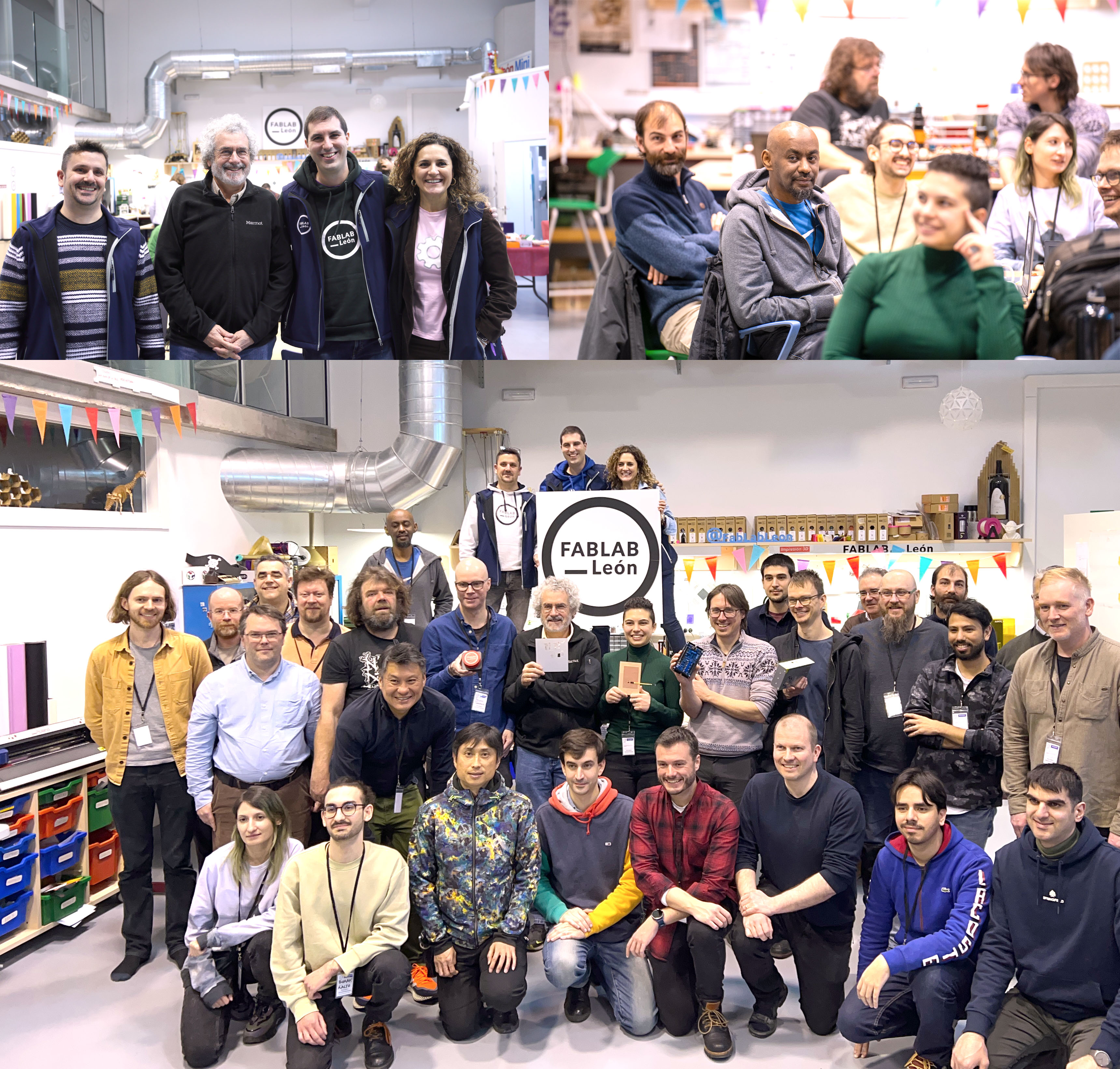
In a dynamic meeting of the minds, Fab Academy Instructors Bootcamp unfolded January 8-12, 2024 in León, Spain. Over 30 instructors from diverse corners of the globe came together, forging a vibrant global network dedicated to revolutionizing digital manufacturing education.
The bootcamp, hosted at Fab Lab León (opens new window), showcased a rich tapestry of workshops and sessions, shaping the trajectory of the Fab Academy 2024 cycle and beyond. The instructors immersed themselves in cutting-edge technologies, from mastering electronics production techniques like the NEW Quentorres (opens new window), proposed by Adrián Torres, to Lunyee + V-bits, led by Neil Gershenfeld, Henk Buursen and Jean-Michel Molenaar, exploring the intricacies of embedded programming and electronics design.
A pivotal moment during the bootcamp was the Midterm review, where instructors tackled project system diagrams, tasks, and schedules, guided by a vision to elevate the quality and impact of final projects. Neil Gershenfeld, the visionary founder of Fab Academy, added his touch, urging instructors to polish documents illuminating the construction, production, and operation of final projects—empowering future students with comprehensive insights.
The workshops were an exploration of innovation. Instructors delved into realms that define the avant-garde of advanced manufacturing—from the Ferret Pro (opens new window) scanner unlocking new dimensions in 3D printing scanning to workshops on Blender nodes, CAD Sketcher (opens new window) by Rico Kanthatham and Adai Surinach, as well as Modular Things CoreXY (opens new window) by Andri Sæmundsson and Yuichi Tamiya. A special mention goes to the Urumbu Sambot workshop, led by Jani Ylioja, which focused on embedded languages and provided instructors with tools to navigate the complexities of programming languages.
The bootcamp set the stage for a transformative journey. Instructors laid the foundation for a global community of machine builders, pushing the boundaries of open design and collaborative learning. A shared vision for the future of education emerged, in which Fab Academy harnesses 15 years of experience to be a beacon of hands-on, inclusive, and globally coordinated learning.
The Fab Academy Instructors Bootcamp was not just a gathering; it was a convergence of pioneering minds shaping the future of digital manufacturing education. The journey has just begun, and as the vision takes root, Fab Academy stands poised to redefine the learning landscape.
Stay tuned for updates as the Fab Academy 2024 (opens new window) cycle unfolds, bringing a new wave of innovation and skill-building to students worldwide.
Full documentation here (opens new window).
# NOVEMBER 2023
# Calling all Tinkerers, Makers, and Innovators!
Are you looking for an adventure to spark your professional curiosity? Do you want to ignite your passion for learning, making, and doing? Reinvent yourself—and the world around you—at Fab Academy.
Fab Academy is a fast-paced, intensive education program dedicated to the exploration of advanced manufacturing techniques and methodologies. A multi-disciplinary and hands-on learning experience, this five-month course teaches students to envision, design, and prototype innovative solutions through digital fabrication. Since 2007, the program has transformed learners of all ages and backgrounds into active problem solvers building sustainable communities across the world.
“If you empower somebody to produce…it fundamentally changes how an economy works. What are the implications of anybody being able to make anything?”
Neil Gershenfeld Director of MIT’s Center for Bits and Atoms & Co-Founder of Fab Academy
Responding to the evolving needs of industry and the demands of modern society, Fab Academy has pioneered a global education movement that challenges traditional approaches to learning. This has resulted in an outgrowth of jobs, projects, businesses, and initiatives by shifting the linear industrial paradigm toward a circular, distributed, and locally productive model. With our globally distributed approach to education, students are first gathered in peer groups at local Fab Labs for interpersonal working sessions. Each regional group is then connected in an online campus for interactive video classes and content sharing with classmates from over 65 distinct Fab Academy nodes around the world. The international faculty gives video lectures, supervises academic content, and guides student research. Hands-on support in the Fab Labs is provided by instructors—experts in their respective fields—who supervise and evaluate certificates, develop and disseminate instructional material, and assist with projects.
Our program is open to students, professionals, and lifelong learners across all disciplines who are looking to broaden the scope of their practice. While some prior knowledge of design, electronic programming, and web development may be helpful, participants from every walk of life are welcome, regardless of experience. To ensure success in the course, however, we ask that applicants be proficient in English, both written and spoken.
# November, 2020
# Check our Fab Academy Alumni Stories...
# Fab Lab Irbid's students talk about their Fab Academy experience
# Marks Calderón from Peru
# Inspiring Women - Alejandra Diaz de León
# Get Inspired with Daniele Ingrassia
Check out more inspiring stories on our Youtube channel (opens new window).