Esky Mate - The Laziest Invention
Jaryd's Individual Page
Liam's Individual Page
Project Hero Video
Idea and Design

We wanted to make something very Australian, something that every Aussie would take one look at and wonder why they didn't think about that before. We are a nation of BBQ goers and the one thing at every BBQ is an esky (a cooler box or icebox for our international audience) to keep drinks cool on a hot summers day. And the most dreadful first-world problem we Aussies face is having to get up to grab another drink from the esky. But what if the esky came to you...
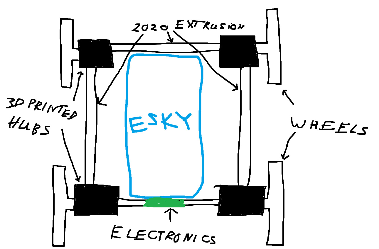
The plan was simple, we attatch an esky to something that could drive it around. We wanted it to be all terrain so that it didn't matter whether you were at a beach BBQ or a BBQ in the park, and we wanted it to be able to haul upto 25 kg of ice and drinks. We settled on using what we were familiar working with, 3D printed parts and 2020 extrusion. The frame would have 4 hubs which served as bearing blocks for the wheels, and would hold the chassis together. We had a few different ideas for locomotion, tank treads, shuffling, but due to simplicity and ruggedness, we ended up using 4 wheels which will pivot turn like a tank.
To start with, we compiled a list with all the parts we would require so we could design around them. Here is the total list
- 5x Aluminium 2020 Extrusion
- 4x Metal DC Geared Motor - 12V 50RPM 50kg.cm
- 2x Dual 7A DC Motor Driver
- 4x Polulu 6mm Shaft Aluminium Mounting Hubs
- 1x Raspberry Pi Pico W
- 1x Protoboard
- 3x 1m of 12mm aluminium tube
- 8x 35x47x7mm bearings
- Lots of M3, M4, M5 bolts and 2020 extrusion T-Nuts
We deciced to play to our strengths and divied up the work - Liam would deal with the electronics and software and Jaryd would deal with the mechanical side of things.
Mechanical Design
We started by desiging the hubs that would hold the 2020 chassis together and allow us to mount the wheels and the motors to them. We figured that if we left enough 2020 exposed on the chassis, we would have no issue figuring out how to mount the esky.
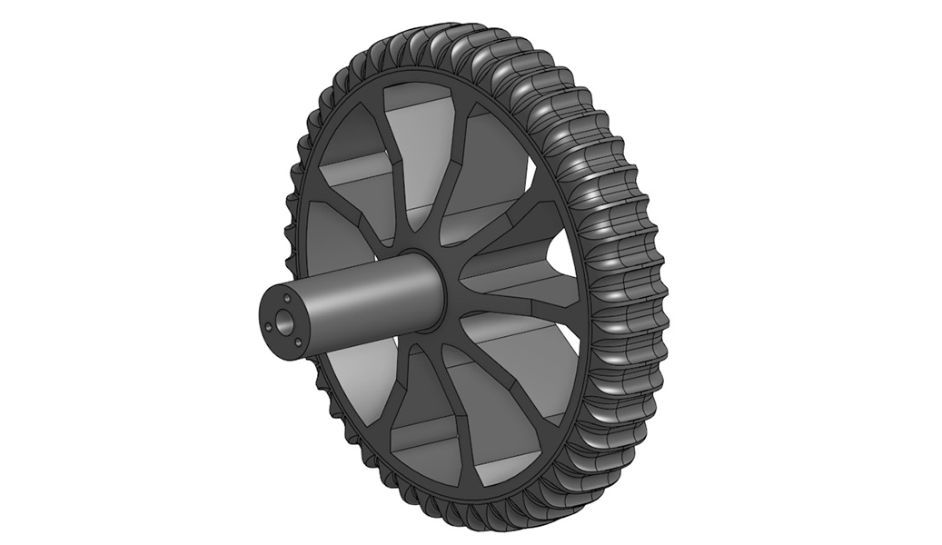
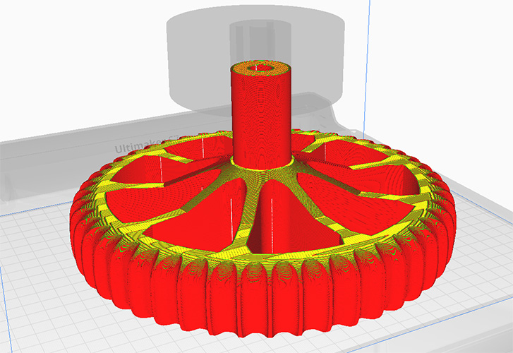
The mount was designed as it was modelled in onshape, starting with the wheel. We had very slow motors and decided to max out our printer's build volume and make the largest wheels we could to remove the need for any gearing - meaning we could directly drive the wheels with the motor. The outter design of the wheels where they contact the ground were copied from that of a dirt bike (but without the directional V shape as we wanted it to turn both ways). The inner spokes were chosen so that when the model is sliced, it will have some nice solid walls for support and not have to rely on infill. The axle was also modelled into the wheel.
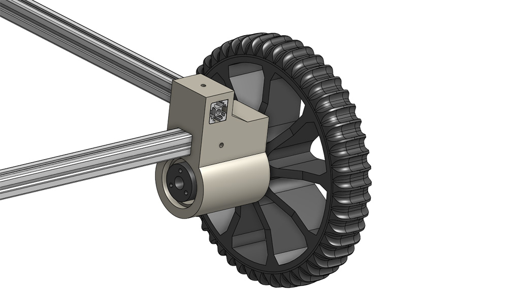
Then the hub to connect the 2020 extrusions was modelled. As with all parts it was designed to be printed without support. This hub mounts to the 2020 extrusions, and holds the axle of the wheel with the bearings.
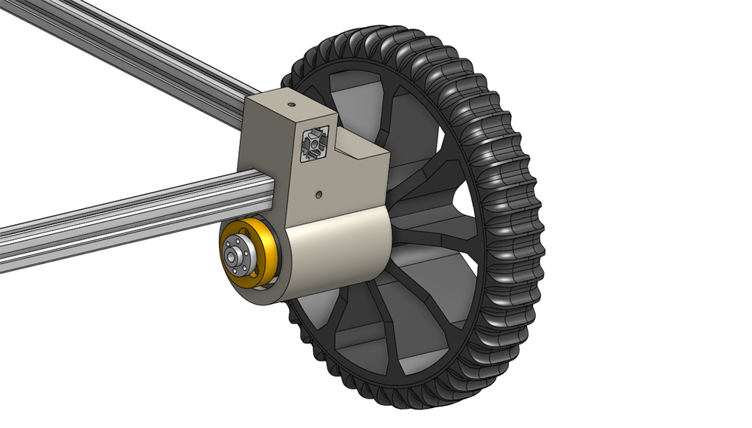
On the end of the axle, a cap (the yellow thing) bolts to it with 3 long bolts. The wheel firmly hugs the hub and the bearing on the outside, and this cap hugs the bearing on the inside, meaning that the wheel and axle are locked in place. We also modelled the 6mm Polulu mounting bit for the motors
And finally we modelled the motor and a mount for it. We decided to make the motor mount a seperate piece that could independantly slide along the 2020 as it improved printability and would make it easier to assemble. And with that, our CAD phase was done for now as we would need 4 identical sets of these parts to make the robot.

3D Printing
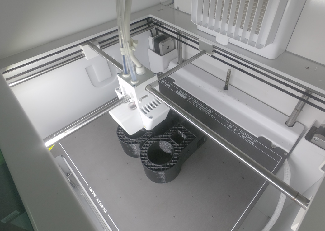
With long print times ahead for the wheels, we decided to utilise the Cura Ultimaker 7 we had access to at work and printed them overnight. We chose PETG as it has improved mechanical properties over PLA, and is still quite easy to print. We printed everything on the thickest layer height of 0.3 mm and chose a rectilinear infill of 8% as these parts were mostly reliant on wall thickness for strength (which was left at the defaults).
The only different part to slice was the wheel which the top 30 mm was modified to have a 60% infill. This is because the cap mounts to the wheel's axle with 25 mm long bolts, and this is how power will be transfered from the motor to the wheels, so a little extra reinforcement was chosen.
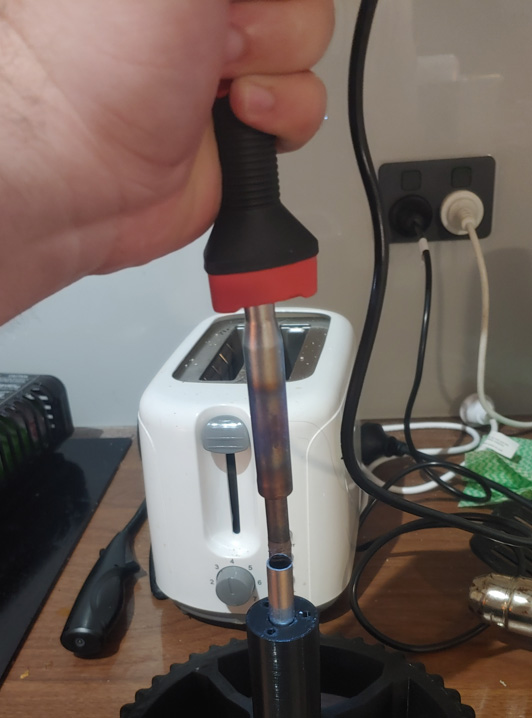
Another issue with the wheels is that the axle is printed parellel to the Z-axis, meaning that it runs along the weak orientation as a result of the print lines. This is an issue that will be fixed by inserting the 12mm aluminium rods through. We have a cool process of how this is done coming up.
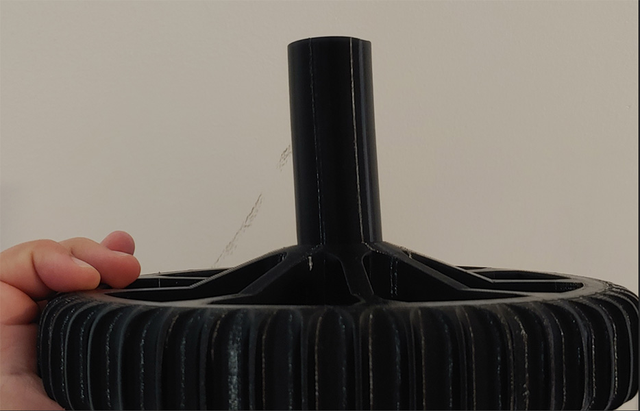
And after about a week of printing, all of our parts were done and ready to be assembled.
Construction
Before we could build it though, we hit a terrible snag. The 3D printed parts were left in a car during a terribly hot summer day and all the printed parts had warped a little. The 2020 extrusion no longer fit in the hubs, and the wheel's axles had bent over a little in the heat.
However, after a few cycles of heating and cooling in the oven and with a heat gun, the parts mostly returned to their original states as they seemed to have a bit of "memory" about their original shape.
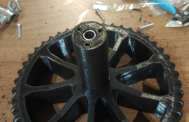
After that process, we could start building. The first thing was to sink the 12mm aluminium tube into the centre of the tyres. There was 1 wheel that wasn't in the car in the heat, and it was easy to sink the tube into by cooling it in the freezer for 20 minutes, then malleting it into position. When it reheats and expands, it braced against the inside slot in the wheels axle.
The other wheels though had warped too much in the heat and this trick wouldn't work, so i heated the up with the biggest soldering iron I had, and sunk them in like threaded inserts.
Then the bearings were malleted into the hub.

And the Cap and shaft hub mounted on top.

And then 2020 extrusion was mounted, as well sa the motor and motor mount.

This process was repeated until the chassis was complete.
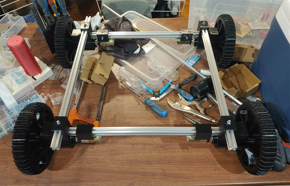
We were quite happy with how this came out, and it was a great excersice in not only CAD design, but CAD design for printed parts and desiging assemblies for ease of construction.
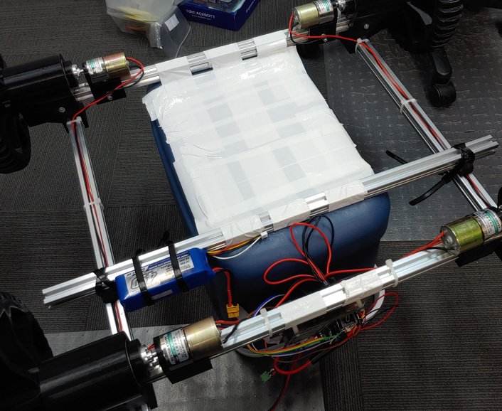
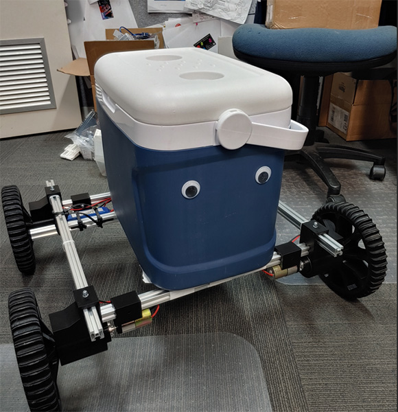
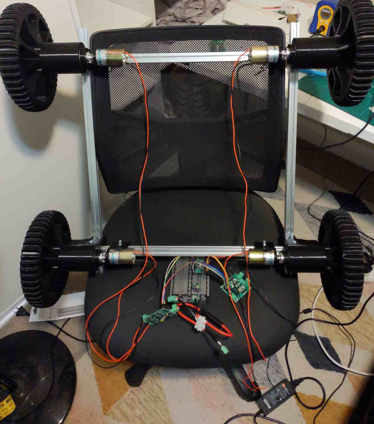
This where the niceties of the project ended as the deadline aproached and we had to mount the esky and electronics. We intially planned to epoxy some mounting points to the esky which would mount to the 2020 extrusion, and a similar idea for the electronics. However, we achieved the same result (close enough) with a large amount of duct tape and cable ties.
And with the final addition of some googly eyes, the mechanical phase was finished.
Electronics
If the 3D prints, aluminum extrusion and wheels are the body of the robot then the electronics are the nervous system and muscles.
The brain:
Both Jaryd and I love the Pico/Pico W so decided to go with one as the thinker for our robot. If we had more time we could have also included a Pi SBC to do more complex tasks and parsed meta data to the Pico to control motors
Controlling the robot:
We knew we wanted some sort of remote control, everyone carries a phone so some solution using a webpage and WiFi seemed feasible. A stretch goal: an AI guided robot waiting for a whistle or gesture then it would find whoever was requesting it and moving towards them.
Making the robot move:
An esky filled to the brim with goodies will weigh a lot, so we needed powerful motors and hence big motor drivers (while minimising cost) We went for these high-power motors from DFRobot to give us the oomph we need to move on sand. And these 7A per channel motor drivers that operate from a 3.3V logic level.
Integration
To make everything neat we used a protoboard and an acrylic mounting plate to keep all of our finiky electronics in the one spot.
The following electrical layout would be required for our robot to work.
Battery -> Regulator -> Pico -> Motor drivers -> Motors
Circuit design
During testing we could use a wall power supply and when on the move a 3S quadcopter LiPo would be used.
To keep the battery (and us) safe, we would fuse the main input line.
Powering the brains
Liam found this regulator in his boxes of stuff. Since the regulator did not include reverse polarity protection a schottky diode was added. We also wanted to be able to plug in a USB and diagnose the robot while it was powered up. We would have to add a schottky diode from the 3.3V output to the Vsys pin on the Pico.
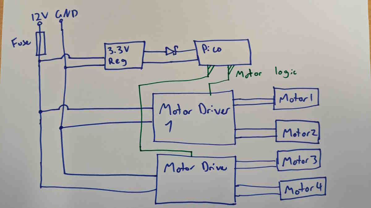
Makin it move
Jumper wires were connected from the Pico to the Vio, EN, IN1 and IN2 pins on the motor drivers.
We finally arrived at the completed electronics:
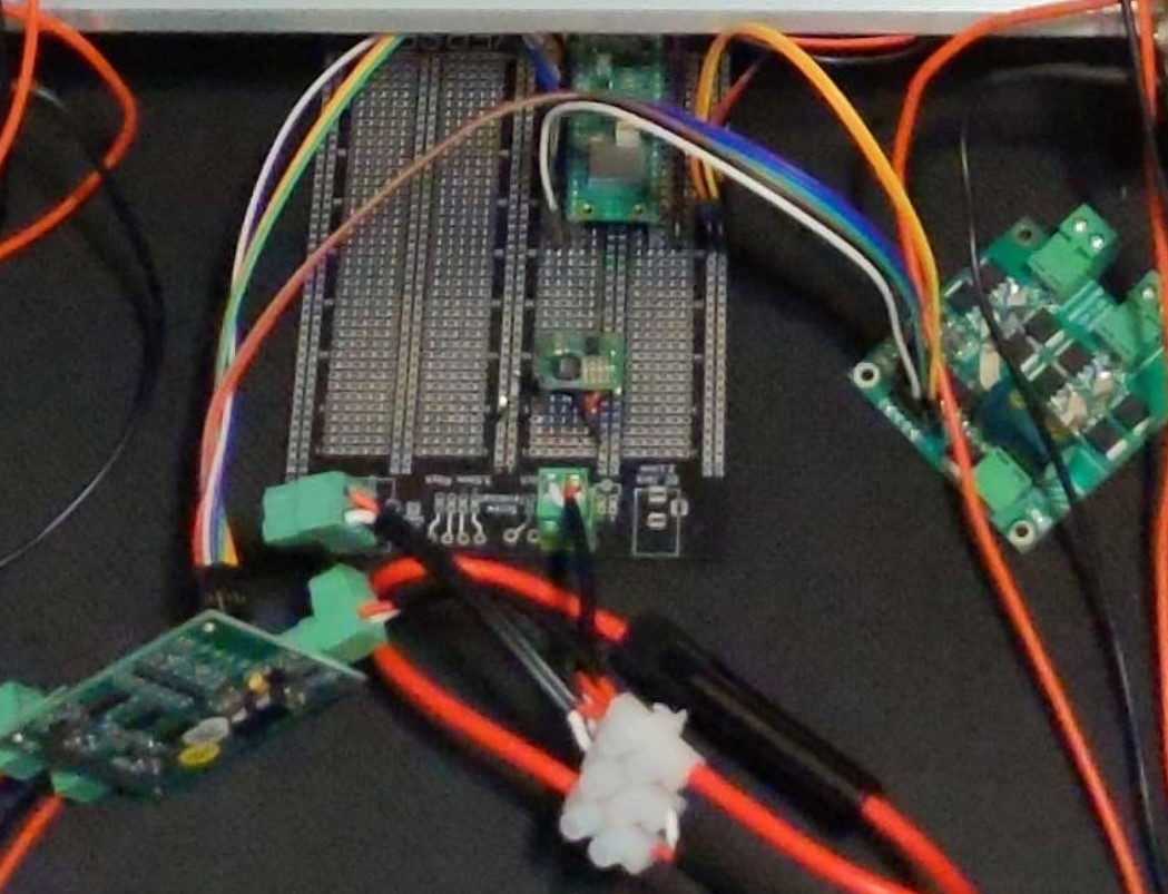
Testing
Liam plugged it in and lots of LEDs came on and nothing let out the magic smoke, WOOOOOOOOOOOOO!!!! Nah, each component was unplugged, power applied and different points measured with a multimeter as components were added back.
This was a shot during testing:
Making it think
How do we control the motors? ChatGPT surely knows... ... And it did, with some modifications after breaking the functions up we had just what we wanted.
We found an analog joystick and mapped it using that class:
And would you belive it... it didnt work, we flipped some of the directions in code and then it worked! (though we didnt use the joystick in our final robot)
Making it think (wirelessly)
The Pico W includes Wifi, and allows an access point to be hosted from the device itself.
We wanted our webpage to include some interactive elements, not just a few buttons for forward, backward, left, right, and stop. GIVE US SOME SLIDERS!!!!! Of course we went to ChatGPT, we are lowly mecha's not web devs (the code will work... but not amazingly).
https://chat.openai.com/share/9caf3281-fe0c-4171-ab44-5ce5e005a3b6 We continued to feed this code through GPT with many many prompts to get it into its final form:
Testing it all together
Besides flipping the motor directions again, testing went alright. I hit one issue while testing at Core, where there were too many WiFi bands being used, not allowing us to connect to the AP it sets up. I moved around the building until the WiFi was a bit weaker and it worked great!
Future Improvements
The first improvement would be to mount the esky to the chassis in a better manner than duct tape. It did work, but it was a little janky sometimes and slid around a litle, but it worked with the little time we had. If we had our time again there would also be a few changes we would make including: - Making the wheels wider so they get more traction - Chaning the webpage being served to be a little more robust and easier to use (maybe a kill button that stops the bot) - Or changing the control method, when outside the esky would block the wifi signal and at the beach with nothing to reflect off it would create large deadzones
If we had an entire semester to do this though the biggest improvement we would make would be to make it water and salt proof. Everytime we took it to the beach we would have to completely dissasmble the robot and give it a thoughrough clean to keep the salt our of the bearings and electronics. Even then the bearings grew noticably "crunchier" every time we did so. I dont know what it would entail, but it would likely need a complete redesign.s
Files
The STL files for this were extremely large (mainly the wheel), so here is a link to the CAD files to export STLs from
Online Link to Onshape File
Offline STEP File