Week 12 - Mechanical Design, Machine Design
Mechanical Design (part 1 of 2)
Group assignment:
• Design a machine that includes mechanism + actuation + automation + application
• Build the mechanical parts and operate it manually
• Document the group project
Machine Design (part 2 of 2)
Group assignment:
• Actuate and automate your machine
• Document the group project
Overview
Before building the coin sorter, our group (basically just two people) looked at the different types of coin sorters that had been made previously. You can find our YouTube Playlist here.
We decided that we liked the simplicity of this version from this YouTube (The Q) and proceeded to work out a plan to make something like this.
Division of Work
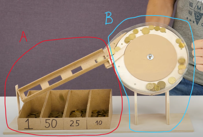
The plan was simple, since there are only two of us in the group, we will each work on the two different sections as follows:
A) The coin-sorting gates and coin collectors,
B) The coin feeder.
While each section will be our individual responsibility, we will also have to work collaboratively to integrate the entire sections of the machine such as the structures that hold the different components together.
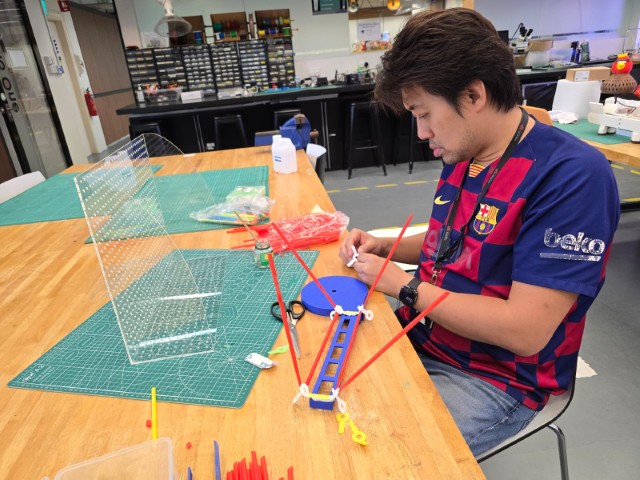
Mechanical Design (Manual Operation)
Our first tasks were to model and build manually operated sections for A and B and then test if the sections work as intended.
A) The coin-sorting gates and coin collectors
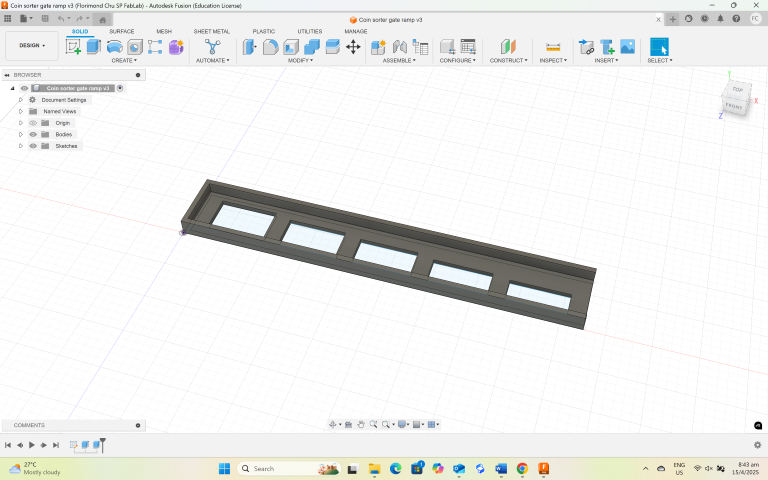
For this part, we sketched out the design of the coin-sorting gates (parametrically) in Fusion 360, and then exported the STL file out to 3D print on our lab’s Bambu X1-C 3D Printer.
We tested the coin-sorting gates by manually feeding the coins onto the ramp and then let them slide down the ramp to see if the coins will drop into the correct coin gate.
Below is a video recording of our test.
As seen in the video, the coin gates work properly as intended. We also observed that a smaller coin might drop into the wrong coin gate if “piggybacking” on a larger coin. This is why it is critical to feed the coins in one at a time.
B) The coin feeder
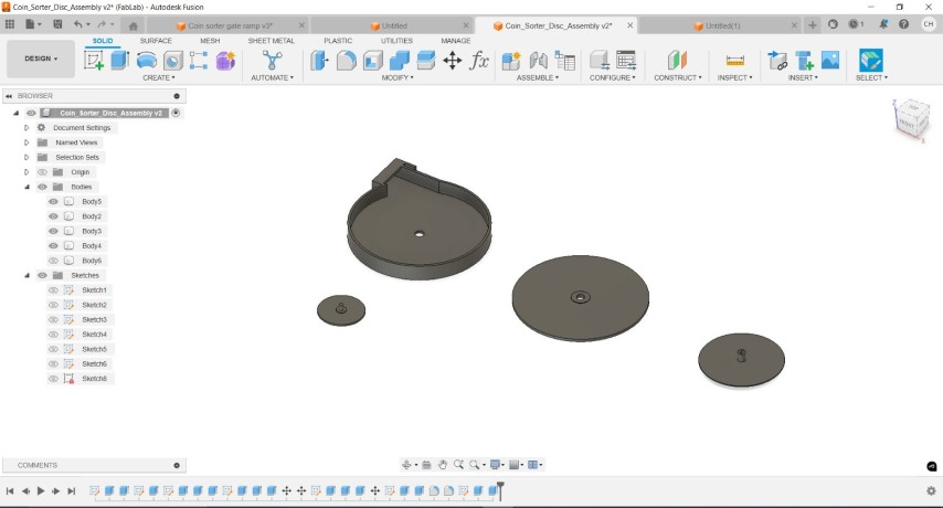
For the coin feeder, we start by modelling a suitable size of the disc so that the coin feeder can transport the coins (of various sizes) smoothly from the bottom arc of the disc to the top arc. We use Fusion 360 to model the disc as shown below.
Our first disc failed to bring the coins from the bottom arc to the top arc because there wasn’t enough friction. The solution was to increase the friction of the disc by adding a layer of sandpaper to the disc. As you can see from the video below, we were able to manually operate the disc to transport the coins from the bottom arc of the disc to the top arc.
Both sections together
Having successfully tested both sections, we put them together and operate it manually.
At this point, we are just holding the parts in place with our hands but moving forward, it is obvious that we will need to create some kind of frame or structure to hold the parts in place.
Machine Design
We created a peg board frame using a laser cutter to make it easy for us to mount and test the optimal alignment and slope of the coin feeder/coin sorting gate mechanism.
However, before we can design any type of connection for it to mount, we need to find a way to support our coin feeder/coin sorting gate mechanism. The thinking was that if we could fix the optimal alignment of the coin feeder/coin sorting gate mechanism, we can then create the necessary connections to mount it to the peg board frame.
Strawbees Trial
We started using Strawbees, a children’s construction and prototyping kit to create the structures to hold up our coin feeder/coin sorting gate mechanism so that we can take measurements of the distance between the different attachment points of the mechanism to the peg board frame. The thinking was that we can quickly build up a structure to hold up our coin sorter, but this proved futile, as the straw construction was too flimsy to provide the required stability to take accurate measurements.
Ball and Socket Joint Mounts
While our trial with Strawbees did not yield any positive results, it was not completely pointless. At some point of our unsuccessful trial with Strawbees, we grabbed a ball and socket clamp (that we normally use for soldering) to align the coin feeder/coin sorting gate mechanism. This seemed to work a lot better, and we developed a plan to use ball and socket joints to stabilize, align and mount the coin feeder/coin sorting gate mechanism. We found a suitable ball and socket joint on Thingiverse and adapted the mounting plates to match our pegboard frame.
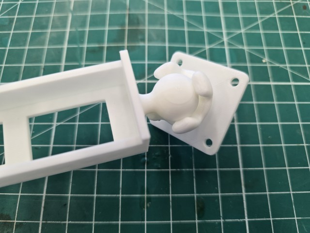
This time, we felt that this solution might work as the ball and socket joint mounts were easy to attach to the pegboard frame and provided a good range of motion to align the coin feeder/coin sorting gate mechanism.
With the first ball and socket joint mount completed and tested, we move on to integrate the ball feature on various points of our coin feeder/coin sorting gate mechanism so that it can be mounted securely onto our pegboard frame.
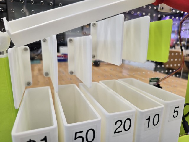
It works but we had an issue with some of the coins dropping into the wrong containers. When the coin drops from the coin gate to the container, there may be unusual deflections that might prevent the coin from dropping straight down.
As demonstrated in the video below, 2 of the 3 coins deflected away from the container instead of dropping straight down.
Deflectors
Observing the path of the coins from the coin-sorting gates to the containers, we realized that we could mount a deflector onto our pegboard frame to prevent the coins from falling into the wrong containers. We came out with this design, and it seems to solve the problem.
We can now move on to the next part - actuating the coin feeder.
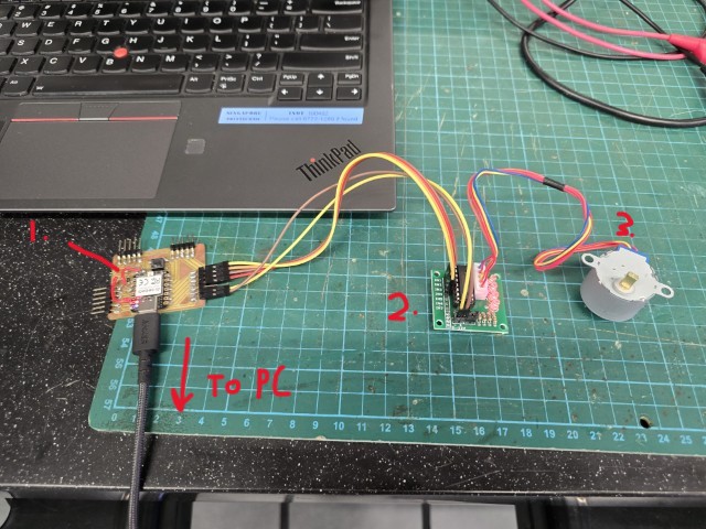
Actuating the coin feeder
We use a stepper motor to drive the rotation of the coin feeder's disc. Pictured below is how we connected the PC via USB to 1) the ESP32 board, 2) the Stepper Motor driver, and finally 3) The Stepper Motor.
We will now need a program to drive the stepper motor, and so we wrote the following program to run the stepper motor.
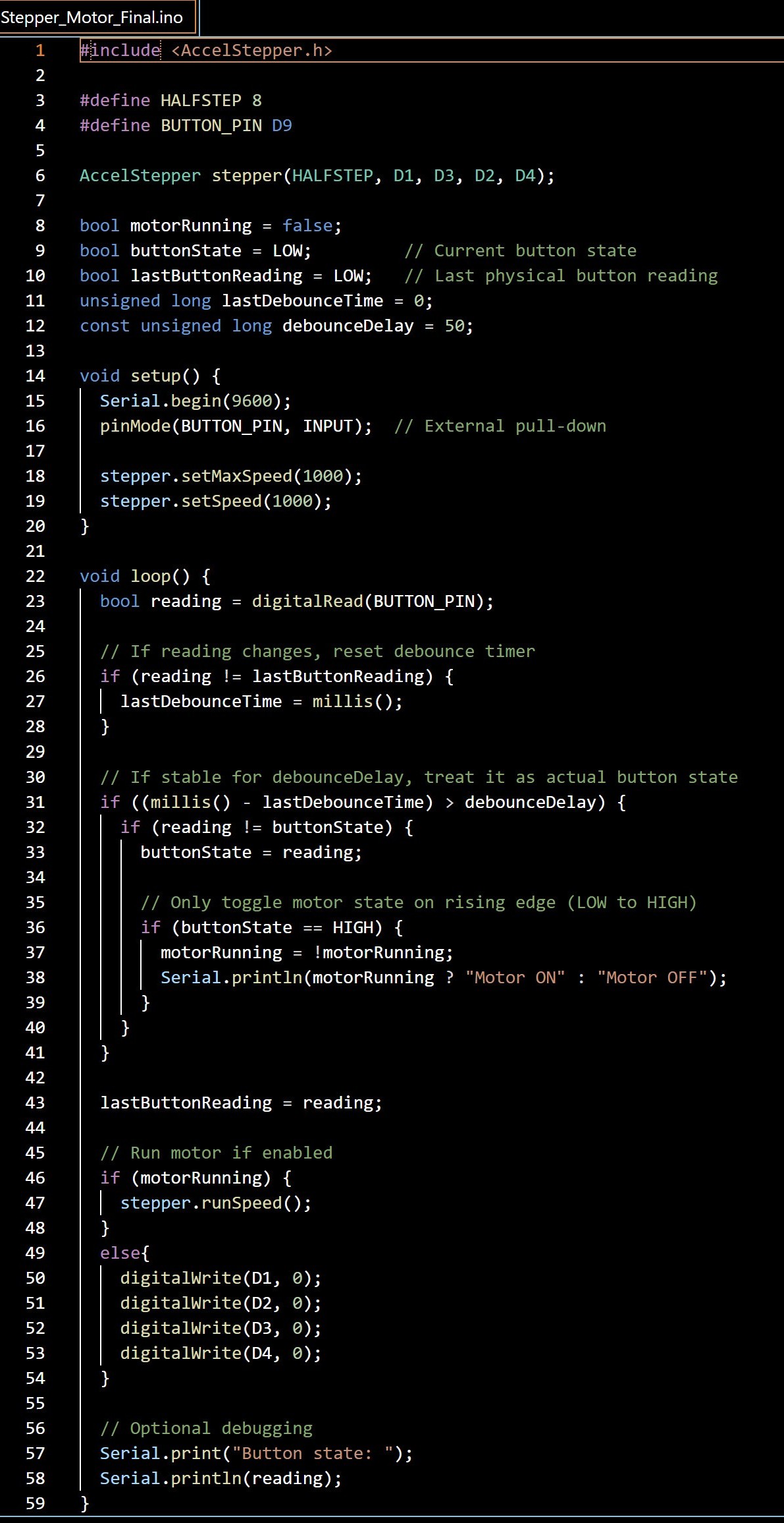
How the programme works
When the built-in button on the ESP32 board is pushed, the Stepper Motor is turned on and runs at a constant speed to turn the coin feeder disc. When the coin feeder disc turns, it carries the coins from the lower arc of the disc to the upper arc of the disc. At the point where the coin feeder meets the ramp containing the coin-sorting gates, the coins leave the disc and roll down the coin-sorting gates, filtering into their respective containers.
When the button is pressed again, it turns off the stepper motor.
Completed Project
With the actuation of the stepper motor, our Coin Sorter machine is finally complete!
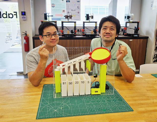
You can view our project video below.
Below is the breakdown of our eventual contribution to the project.
| Machine Component | Florimond | Haw Ren |
|---|---|---|
| Pegboard Frame | Designed, laser cut and assembled the pegboard frame | Helped to apply acrylic glue to strengthen frame |
Deflectors, Containers, and connecting structures (e.g. ball and socket joints, pillars etc) |
Designed, 3D printed and tested these parts | N/A |
| Coin-Sorting gates | Designed the first prototype for the coin-sorting gate | Integrated the coin-sorting gate to the coin feeder. |
| Coin Feeder | N/A | Designed, 3d printed and tested the coin feeder mechanism. Researched and wrote the program to control the stepper motor. Integrated the stepper motor to the coin sorter machine to automate it. |
| Housing for ESP32 board | N/A | Designed, 3d printed and tested the ESP32 board housing. |
| Documentation | Main person documenting this Group Assignment | Supported documentation as Group member |
Learning points
Here are some things that we learned from building this coin sorter:
1. The pegboard frame was a very useful tool for prototyping and working collaboratively. The standard hole spacing helped us to define the dimensions of the various parts we needed to come up with and provided us with a system to attached and align the different parts of the machine. It was also great for quick adjustments and moving parts around as the pegboard system offers multiple points to fit the components.
2. Apart from the pegboard frame, our other favourite tool was 3d printing. We have access to multiple 3d printers in our Fab Lab and this helped us to come up with the parts we needed to complete this project. We could iterate quickly and even when we made mistakes, we could recover from them and adjust quickly.
3. Working collaboratively under tight timelines can be challenging and requires a lot of trust, communication, and cooperation. However, completing a project together with your partner is extremely satisfying.
opportunities for improvement
We are happy with how our coin sorter turned out, but there it can always be better! Here are some possible ways we can think of to make it even better:
1. Durability – We think we can improve the durability of the coin sorter, especially the pegboard frame, where we can use more finger joints to improve the strength of the holding connections.
2. Portability – Right now, the coin sorter is quite large, and it is not convenient to carry it from one point to another. Making the design a bit smaller and more compact, as well as adding features such as a carrying handle will help with this.
3. Hopper – Our current design requires users to feed the coins in using their hand. We thought that implementing some sort of vibrating hopper to feed the coins will make it easier to use.
This concludes our Group Assignment for this week.
Files
Files used in this project - Fusion 360, Laser cutting PDF, STLs and Stepper Motor Program