ScanLab X1
ScanLab X1 You Portal From the Physical world to the Mesh world
This Page is to document the process pf building ScanLab X1
ScanLab X1 was designed and developed by 3 Fab Academy students from Bahrain:
WHY?
In this age and time, products are everywhere. And it is not feesable to scan them manually with your hand.
As instructors of Fab Academy* in Fab Lab Bahrain, we noticed that students sometimes struggle with 3D scanning.
ScanLab X1 helps scanning objects [max size: 10x10x10cm^3] in an easier, faster, and more stable way.
It was also tested for taking videos & pictures of varios products for display, so producers can share it from all angles.
Make it Work:
- Plug the power.
- Place your Phone on the stand.
-
Open your scanning app/camera: The software we tested for scanning was Scanniverse for ios devices. Scaniverse
-
Select the scanning mode. *ScanLab X1 has 3 modes, low resulotion- fast movement, medium resolution, or high resolution-slower movement.
- Press the Button.
-
Wait till process is over. The disk in which the product is placed on will rotate, and the wheel where the phone is placed on will rotate at the same time.
-
Tada! you are done.
ScanLab X1 Breakdown:
Mechanical Design
The main two parts of this project are The Lazy Susan, and the Wheel.
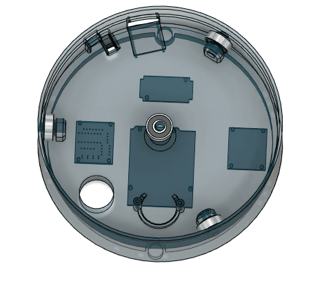
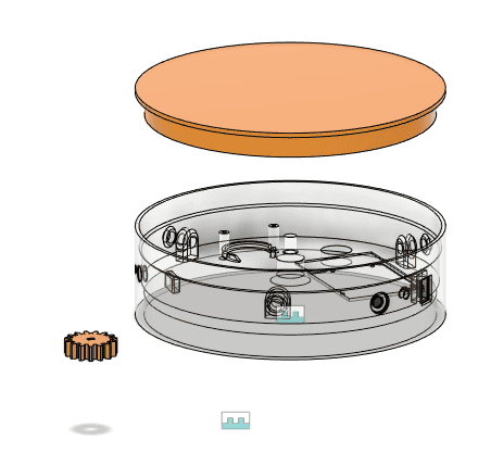
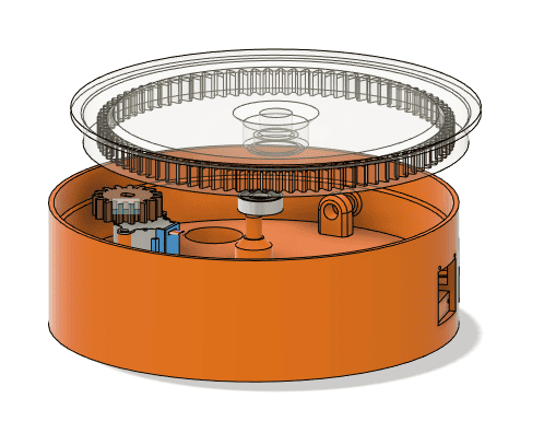
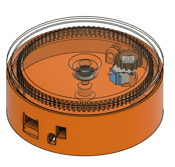
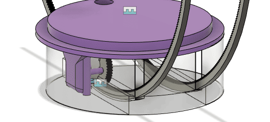
Lazy Susan:
A Lazy Susan is a turntable or rotating platform typically used to provide easy access to items on a circular surface. In the context of a 3D scanning platform, it serves as a motorized rotating base that allows an object to spin 360° horizontally. This smooth, consistent rotation helps capture images or scans from all angles without manually repositioning the object.
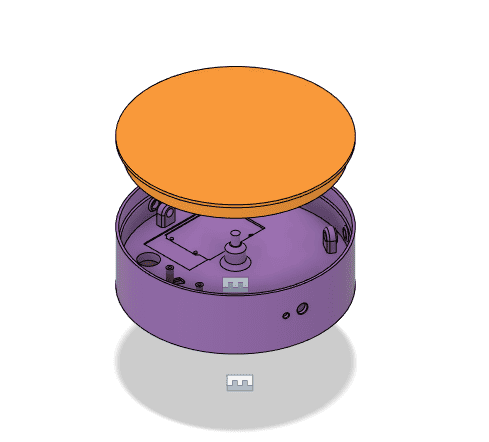
Components:
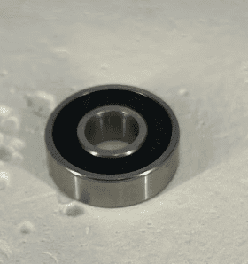
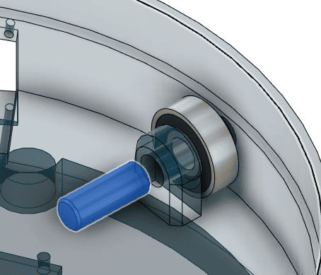
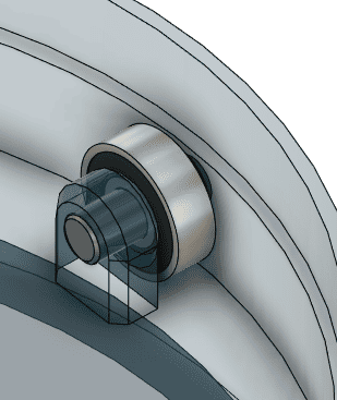
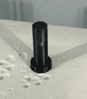
- A circular base: holding 3 bearings on the sides and one on the middle[bearing 608]
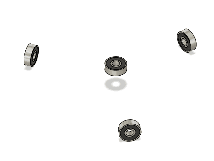
The three bearings on the sides allow smooth movement of the rotating disk on top [which is a gear]. bearings are held using pins to be fixed from the middle part and the surface of them allows sliding movement.
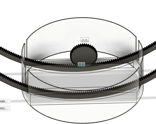
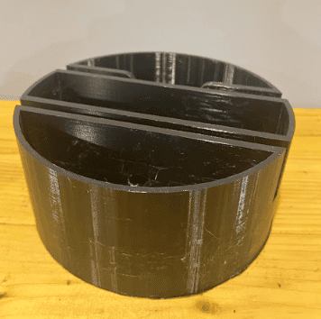
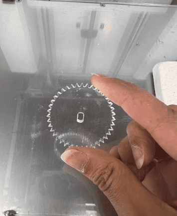
- A Rotating Disk: has gear teeth from the inside that are moving by another smaller gear. The smaller gear is attached to a stepper motor.

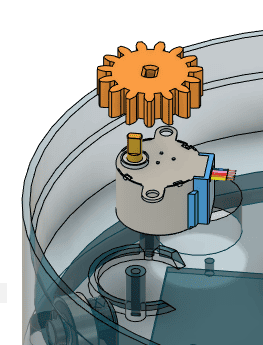
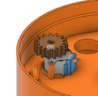
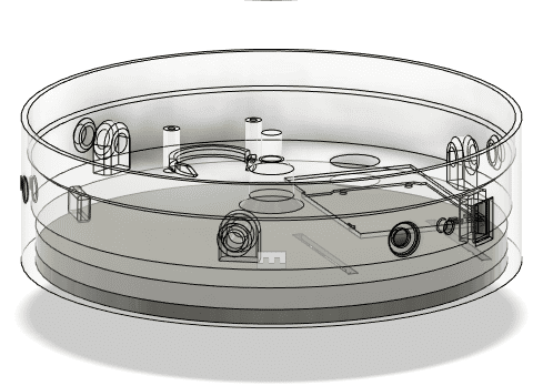
Lazy Susan design uses a well-thought-out gear-driven actuation system for smooth and precise 360° rotation. Here’s a breakdown of how it works:
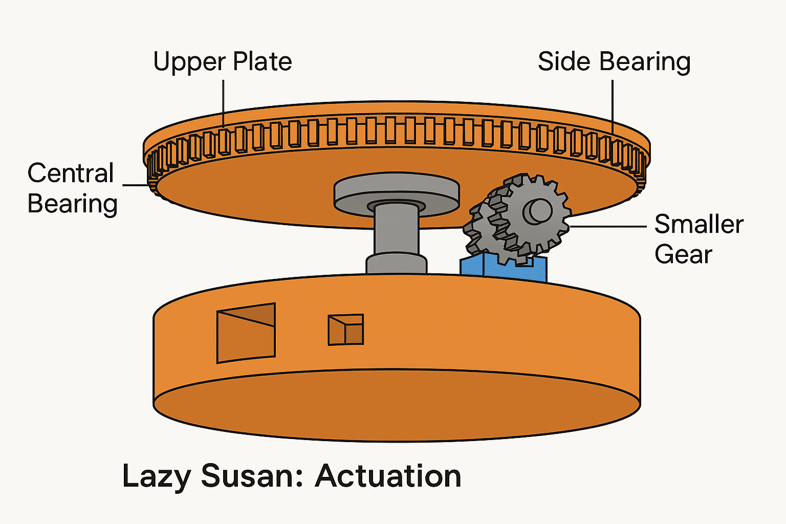
Actuation: A small gear is directly attached to a stepper motor, which provides accurate control over rotation through microstepping.
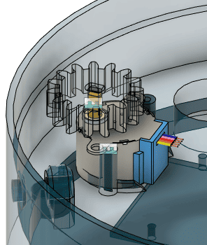
This small gear meshes with the inner teeth of the larger gear, which is integrated into the upper rotating plate of the Lazy Susan. This setup provides torque amplification and smooth motion.
Bearing system:
There’s one central bearing to support the vertical load and keep the rotation stable around the center.
Three additional bearings on the perimeter help reduce wobble and support radial loads, ensuring smooth and balanced movement of the upper plate.
This combination gives you a reliable, low-friction mechanism with precise control — perfect for consistent object rotation during scanning.
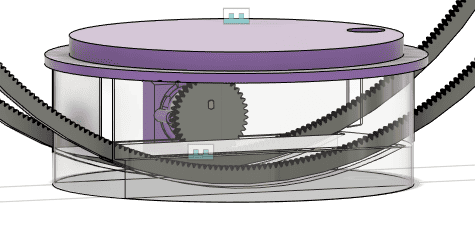
The Wheel:
The wheel in a 3D scanning platform is used to control the vertical orientation of the object being scanned. By rotating the object along a tilted axis, it allows for multiple angles of coverage. When used together with the Lazy Susan’s 360° horizontal rotation, the platform enables a full range of views needed for comprehensive 3D scanning.
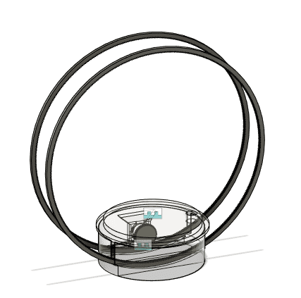
Our vertical movement system is built around a dual-wheel assembly, designed to enable the object’s tilt for complete 3D scanning coverage.
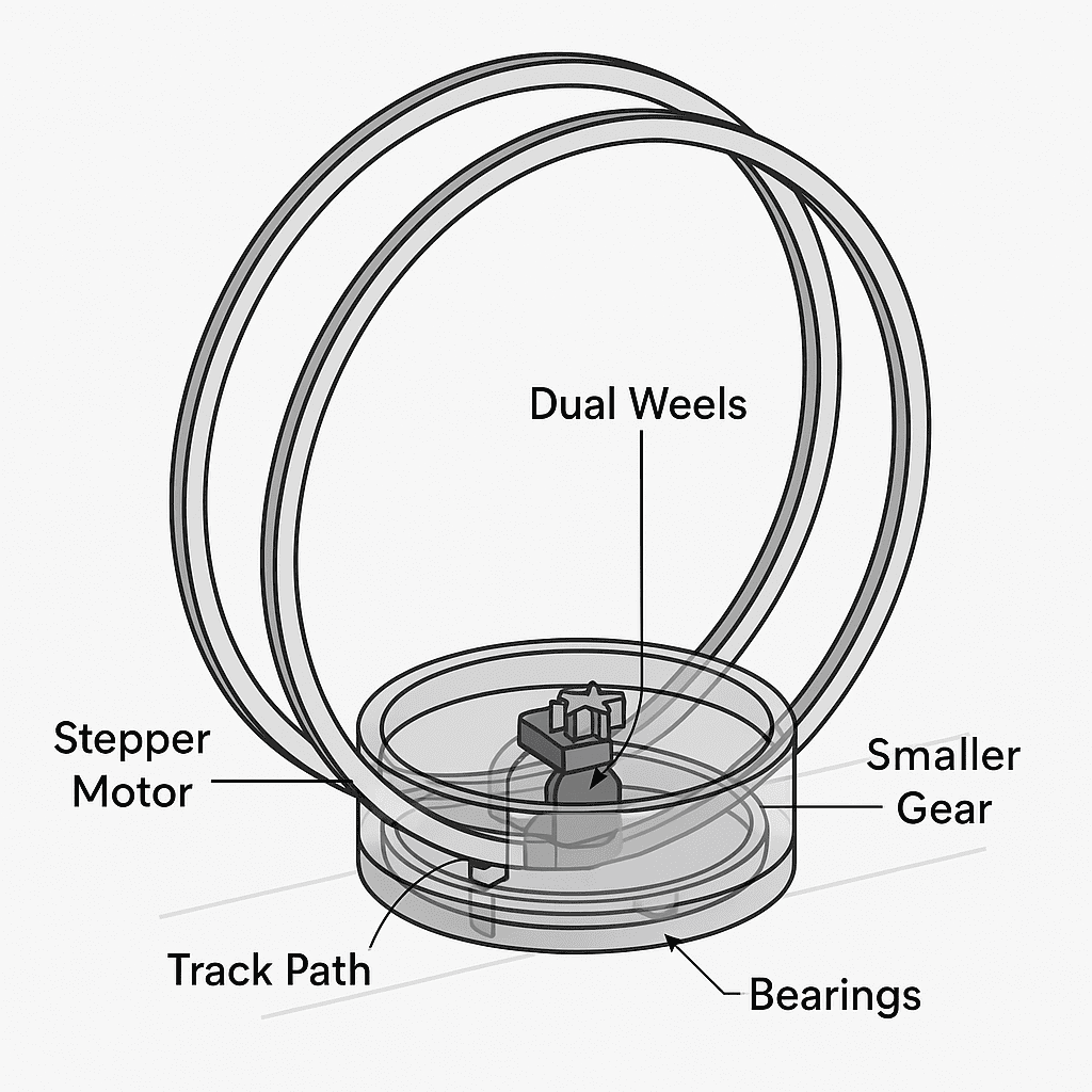
Components:
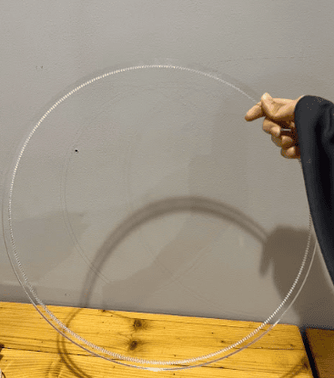
Dual Wheels: Two identical large wheels form a single rotating ring. Each wheel is designed as a gear with inner teeth, allowing precise mechanical control.
Stepper Motor: A stepper motor is mounted near the upper section of the system, fitted with a small driving gear. This motor is responsible for initiating and controlling the wheel’s rotation.
Smaller Gear: The gear attached to the stepper motor meshes with the inner teeth of one of the large wheels to transmit motion.
Track Path: The wheels are seated within a track or guide path, which maintains their position and prevents unwanted lateral movement.
Bearings (x2): Two bearings are placed at the base of the wheel assembly. These reduce friction and provide smoother, more stable rotation.
Actuation: The stepper motor drives the smaller gear, which engages with the inner teeth of the large wheel. As the motor rotates, it transfers motion to the wheels, causing them to spin within the track. The gear pushes from the top, while the bottom bearings support the load, keeping the motion smooth and consistent.
This configuration allows us to control the vertical tilt of the scanning platform with precision. When combined with the Lazy Susan’s 360° horizontal motion, the vertical wheel completes the system’s ability to scan from a full range of angles.
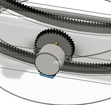
The stepper motor responsible for driving the vertical wheel is mounted on the upper plate of the base structure. This elevated placement allows the motor’s small gear to engage from above with the inner teeth of the wheel. By fixing the motor on the upper plate, we ensure clear gear alignment and provide better structural support. This setup also frees up space in the lower part of the base for bearings and wiring, improving overall organization and functionality.

Electronics:
All the parts we used are common off the shelf parts we found in the lab, so rather than us ordering bespoke items, we went with what we have, and it ended up working out nicely.
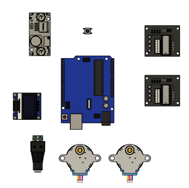
Components list
-
Arduino Uno
-
9V battery + battery snap/connector (or 9V Power adapter and barrel connector)
-
DC-DC buck converter (step-down, e.g., set to 5V output)
-
2× 28BYJ-48 stepper motors
-
2× ULN2003 driver boards
-
0.96” I2C OLED display (SSD1306)
-
Pushbutton (with internal pullup or physical resistor)
-
220Ω resistor (for LED)
-
LED
-
Jumper wires
Wiring Diagram
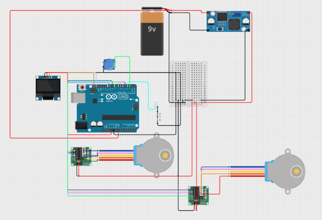
Project Wiring Pinout
Stepper Motors
Stepper 1 (ULN2003 #1)
- IN1 → Arduino pin 8
- IN2 → Arduino pin 9
- IN3 → Arduino pin 10
- IN4 → Arduino pin 11
- VCC → Buck converter OUT+
- GND → Buck converter OUT–
Stepper 2 (ULN2003 #2)
- IN1 → Arduino pin 4
- IN2 → Arduino pin 5
- IN3 → Arduino pin 6
- IN4 → Arduino pin 7
- VCC → Buck converter OUT+
- GND → Buck converter OUT–
OLED Display (SSD1306 I2C)
- VCC → Arduino 5V
- GND → Arduino GND
- SDA → Arduino A4
- SCL → Arduino A5
Pushbutton
- One leg → Arduino pin 3
- Other leg → Arduino GND
(Internal pull-up enabled in code, so no resistor needed.)
LED
- Anode (long leg) → Arduino pin 2
- Cathode (short leg) → Arduino GND (via 220Ω resistor)
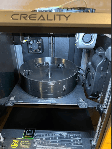
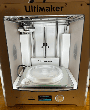
Fabrication
Printing the 3D parts. The bases, and the upper plate and the tracks of the wheel.
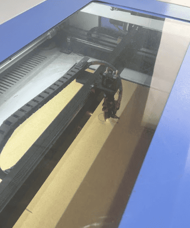
For the wheel, it was made with 6mm acrylic that was cut with laser cutter as the diameter of it was bigger than what the 3d printer can print in one plate.
Assembly and Testing
Once we got all the parts printed and cut, it wasa time to assemble, added to the fabricated materials we had the 608 bearings + stepper motors, motor drivers, and a microcontroller.
- Lazy Susan:
Bearings, Stepper motor, Motor driver, and arduino are added.
We wanted to test lazy susan first by itself.
- The Wheel: