
2. Computer Aided Design
Overview
Okay, so before I get into what software I chose to work with and what I modeled, I want to offer beginners a bit of background and some tips regarding CAD, focusing particularly on parametric design. My goal is to provide you with a comprehensive overview rather than detailed instructions for specific problems.
First, what is parametric design? I’m no expert but I’ve come to understand it as an approach within computer-aided design (CAD) that allows you to use parameters to define the measurements of a shape and manipulate its geometry and dimensions.
Let me give you an example of where parametric design might come in handy. Suppose I want to model a gear. I would need to define several measurements, such as the pitch diameter, bore diameter, face width, tooth profile, pressure angle, the number of teeth… I could define all of these with specific measurements, and that would be fine if I only needed to make one type of gear. But what if I need to make several gears with different requirements? That’s when parametric design comes in. Essentially, you’re not just modeling a gear; you’re designing a gear-making model. This model allows you to produce any gear by changing its parameters. You need to think upfront about which parameters you'll want to adjust. Once you've done that, you only need to change the parameter you wish to modify, and the design will automatically adjust to those new parameters.
I hope that was clear. Now, I'm going to move on to the next topic:
What software did I choose to use?
First of all, I use an ARM based Apple silicon Mac, so I need software that runs well on my machine. Here is the software I chose to use, divided it into 2D or 3D software:
2D Software
For 2D I chose to go with Procreate and Inkscape, the first is a raster image software and isn't free but it's very cheap and it's a one time purchase of only 10$. The second is a vector software and is completely free and open source which is always a good thing.
This is what Procreate's interface looks like:
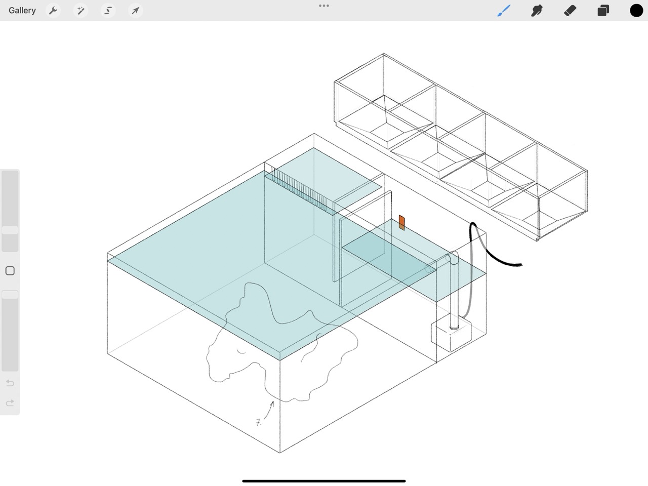
Procreate is a Raster 2D software, this means the canvas is a grid of pixels and as you draw you assign a value to each pixel, selecting it's hue, saturation and value. This means it has a set resolution, if you zoom in you will eventually see a pixelated image.
And this is what Inkscape's interface looks like:
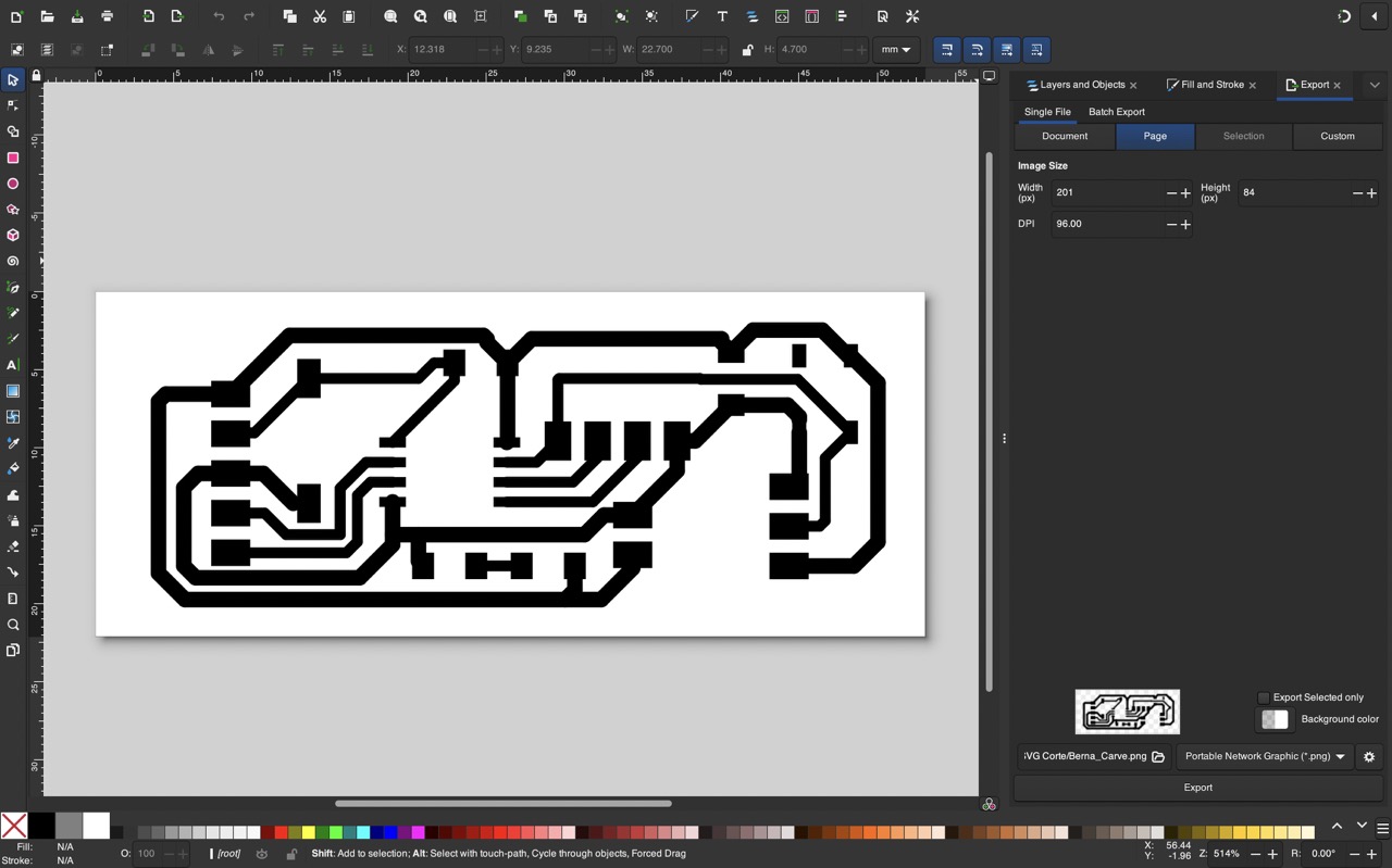
Inkscape as opposed to Procreate is a Vector 2D software, this means the canvas is not divided into pixels, and the drawing isn't defined by pixels but rather mathematical equations which determine the shapes. This means the image has infinite resolution, this is ideal for logo design since you can scale it to whatever size you want and the edges will always look sharp, in this particular case I used it to modify my PCB design. I ensured the scale was correct by choosing the same DPI as the PCB mill is expecting to recieve, if you wish to understand this more in depth I wrote a deeper explanation for the week in which we milled our own PCB designs.
3D Software
I chose two free pieces of software: Fusion 360, which I already had my eye on, and Blender, which is open source and I already use for rendering. I had never used the parametric design features in blender so it was a new experience for me.
To familiarize myself with the two, I first attempted to model the same Lego brick in both using parametric design.
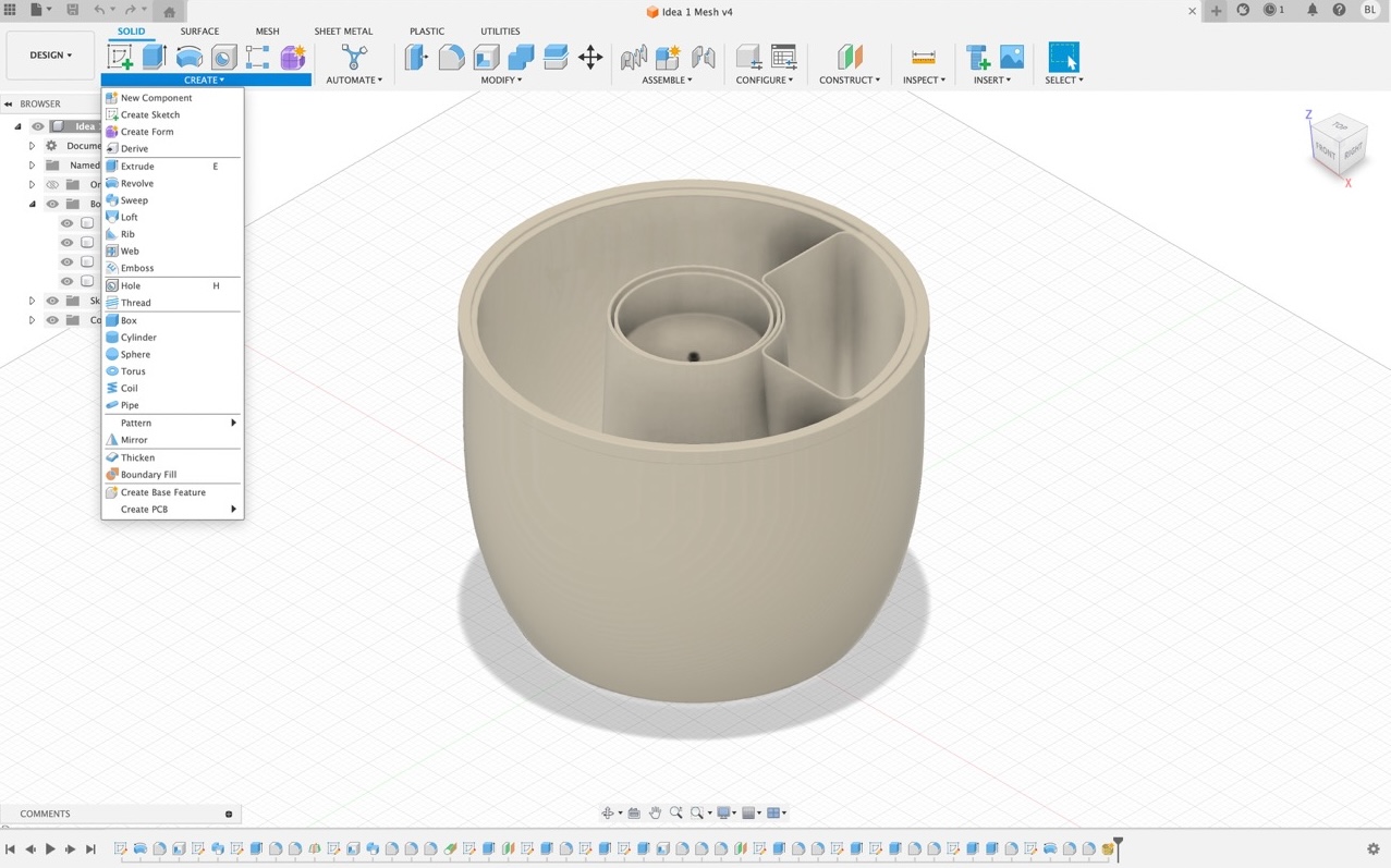
This is what Fusion 360's interface looks like:
And this is what Blender's node system looks like:
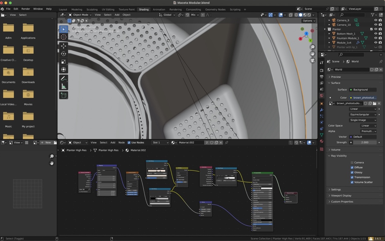
Honestly it looks more daunting than it really is and fusion's looks deceptively simple, learning where to make your sketches in fusion is a little complicated when you start and node systems are really useful for creating procedural shapes or textures.
After this, I decided to focus on learning Fusion since I found its interface more intuitive for CAD and parametric design than Blender’s node system.
Looking for a tutorial showing how to make a lego brick I found a playlist of YouTube videos titled “Learn Fusion 360 in 30 days” so I decided to work through some of these videos to learn how to use more tools in fusion. Here is the link: Learn Fusion 360 in 30 days. I’ve done the first 6 but plant to finish all 30 since they are very clear and I really liked fusion.
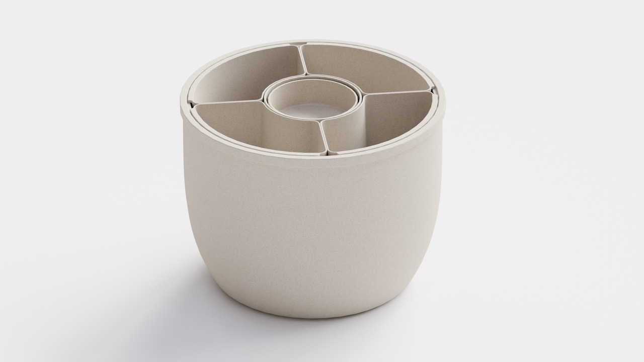
Final Project
After this, I decided to model what I think will be my final project. Following along with the first 6 tutorials made me feel like I could model anything; they seemed easy enough. But once you start thinking about how to apply them to your own design, you realize it’s harder than it seems, especially if you try to stick to your original design instead of adapting it to the tools you already know how to use. By the way, I think that’s a valuable tip: while learning, never compromise your design to fit the tools you’re familiar with. Doing so makes you complacent and hinders your progress, and leads to worse designs in the future.
Renders
Now I know I said I decided to focus on fusion not blender, but... For renders, Blender is the clear winner, I did these in about an hour using cycles as a render engine (which is included with blender for free), a procedural texture and an HDRI image for lighting:
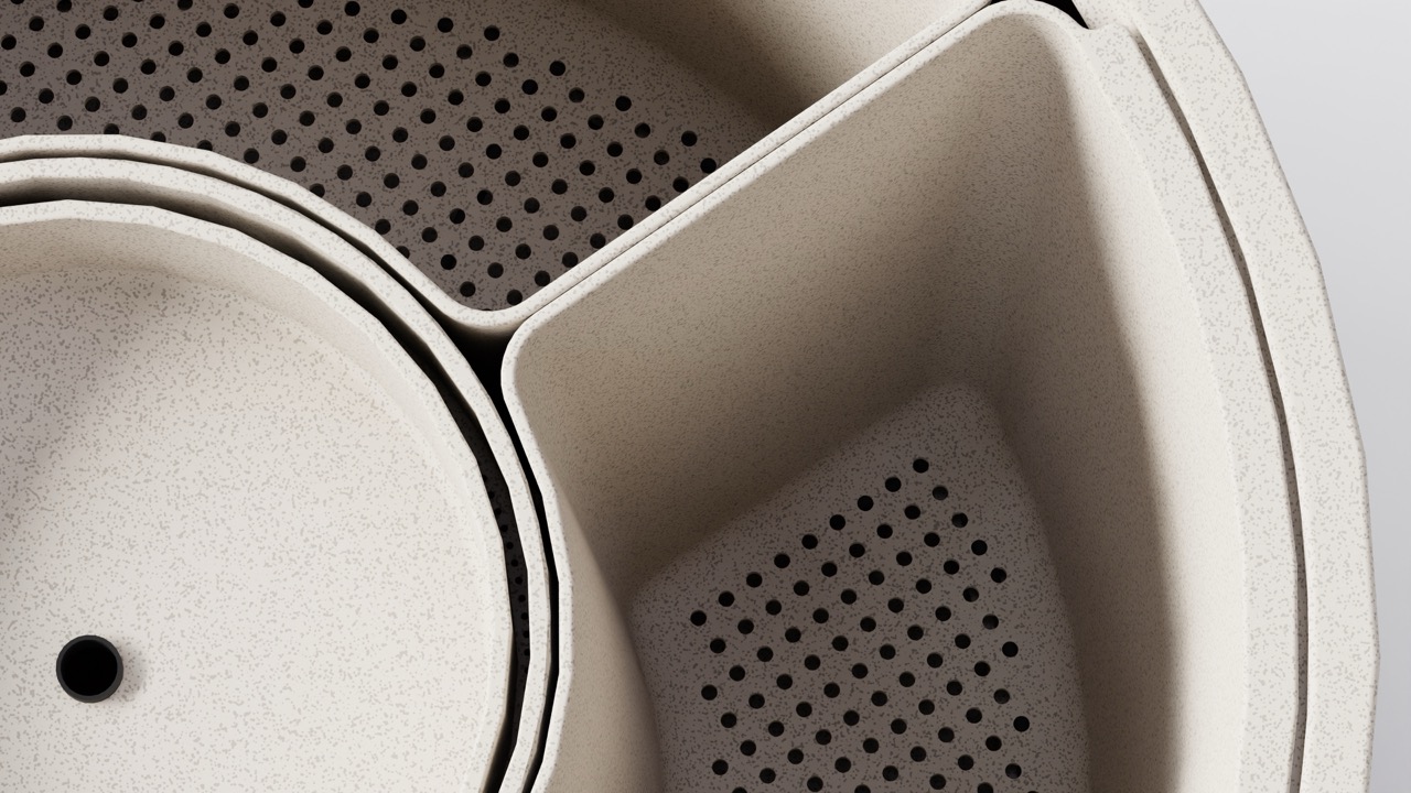
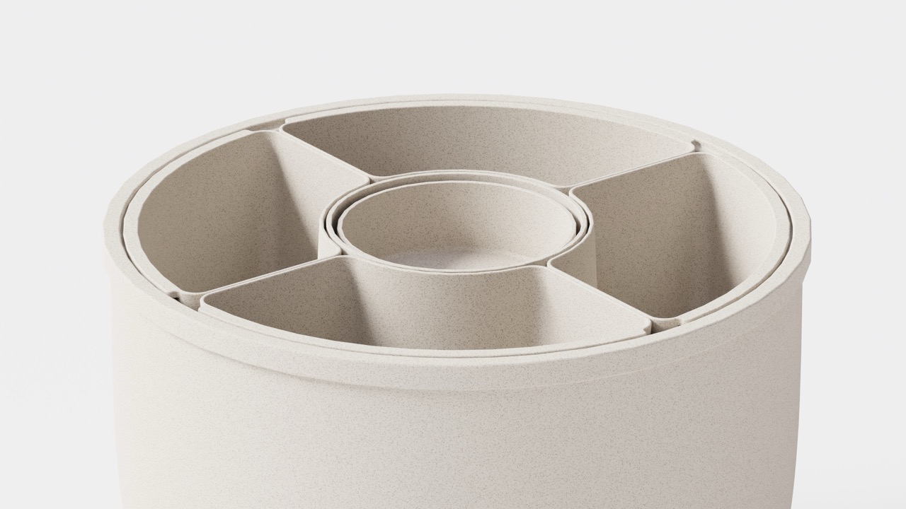
A few weeks later I modified the shape quite a bit and decided to add it to my documentation, and to make a little bit more interesting I tried out an animation which worked out great. I focused on lighting, texturing, camera movement and focus.
- Lighting:
- Texturing:
- Camera Movement:
- Focus:
For lighting I used a combination of area lights and an HDRI. Area lights are basically like photography lights with a difusser and HDRIs are 360 degree Hight Dynamic Range Images which basically create a 360 degree enviornment which emits light. This is great because with relative ease you can light up a scene with relatively realistic lighting. In this case I used the HDRI to create a soft enviornment light and then used the area lights as accent lights to make the product stand out.
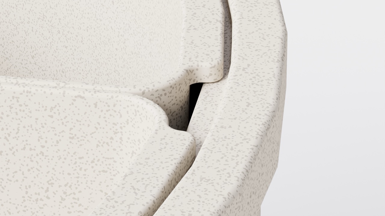
For this I created a procedural texture in Blender. My texture was relatively simple, I just used a noise texture and modifiers to make a spotted pattern which I mapped to the color and used as a roughness map making the dots not only a different color but also different roughnesses making it look like the pot was made out of ceramic and the dots as splats of paint on it. I also added a finer noise texture to the displacement map to make it look rough.
For this I simply created an in and out point, checked the animation, added a third point in the middle to direct the movement a bit more and that's it. Very straight forward.
For focus I activated DOF which stands for Depth Of Field and gave the camera a realistic aperture of F4. Then I adjusted the focus by temporarily changing the depth of field to F0.5 to have an extremely shallow depth of field so I could place the focus in a very specific point. I then ran the animation and animated focus the same way I animated camera movement by adding 3 keyframes.
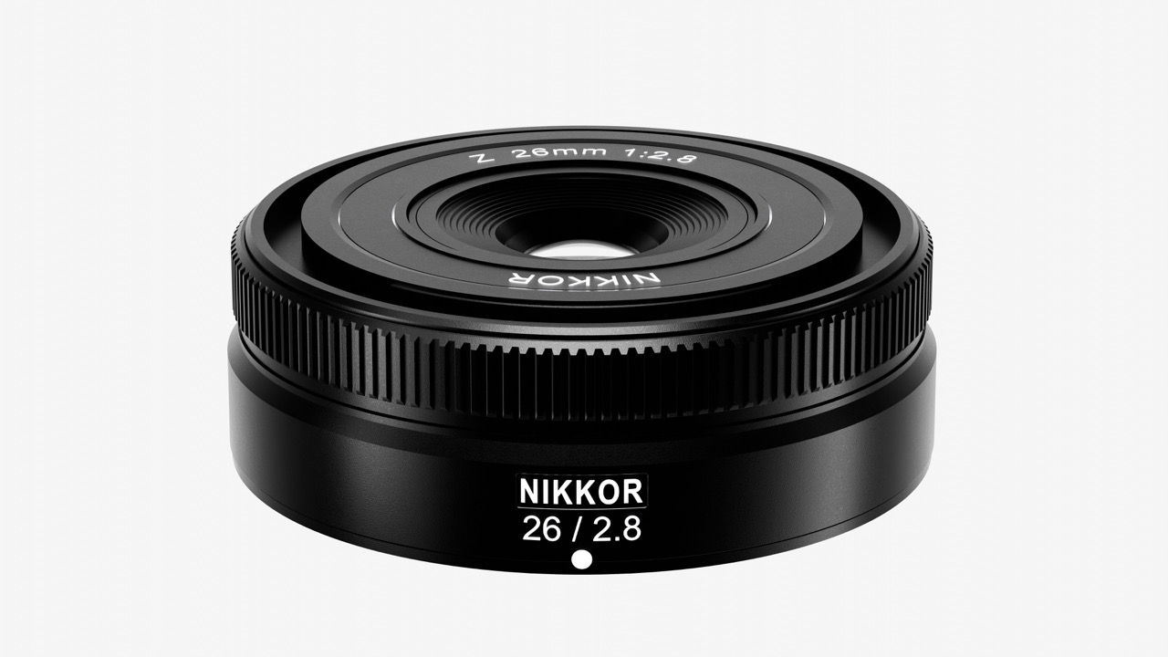
I also modeled and rendered a nikon lens with realistic textures and lighting. I started with a side view reference image which I used to create a drawing which I then revolved. Afterward I cut the small groves in the focus ring by extruding a shape with the cutout. I then projected text onto it to add the lens information.
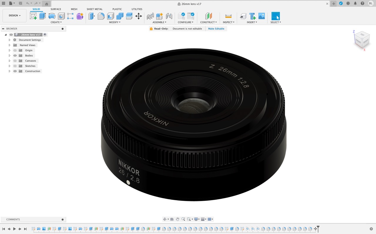
After the modelling was done I exported it in high resolution as an OBJ which I then imported into Blender. There I used realistic textures which I found online and area lights to iluminate the scene. I used a reference image to try to match the lighting and make the render as close to the original as possible.
Files
- Fusion 360 Lego Brick file (exercise 1)
- Fusion Wildlife Fountain
- Fusion Nikon Lens File
- Procreate Final project drawing
- Inkscape Board File