Week 4: Embedded programming
Overview
This week, I worked on embedded programming by simulating a XIAO ESP32C6 and a Raspberry Pi Pico using Wokwi, an online microcontroller simulator. Although I also worked with the physical ESP32C6, this documentation focuses only on the simulation.

Checklist
- ✅ Linked to the group assignment page
- ✅ Browsed and documented some information from my microcontroller’s datasheet (ESP32-C6)
- ✅ Browsed and documented some information from my microcontroller’s datasheet (Pi Pico RP2040)
- ✅ Programmed my simulated board to interact and communicate (ESP32-C6)
- ✅ Programmed my simulated board to interact and communicate (Pi Pico RP2040)
- ✅ Described the programming process(es) I use
- ✅ Included my source code for a simulated IoT air quality monitoring
- ✅ Simulation hero-shot
- ✅ Embedded Programming in Hardware
- ✅ Hardware hero-shot
Group Assignment
In our group assignment, we explored various microcontroller architectures available at FabLab Puebla. We examined their datasheets to understand their performance characteristics and development workflows. Our findings are documented on the group assignment page: Embedded Programming.
Below is a summary of the architectures we analyzed:
| Architecture | Pros | Cons | Main Applications | Common Microcontrollers |
|---|---|---|---|---|
| AVR (8-bit) | Low power consumption, Simple to program, Good community support | Limited processing power, Fewer advanced peripherals | Hobbyist projects, Simple embedded systems | ATmega328, ATmega32u4, ATtiny45, ATtiny44, ATtiny412, ATtiny1614 |
| ARM Cortex-M0+ | Energy efficient, Wide range of tools, High performance for 32-bit | More complex to program than AVR, Higher cost | Low power applications, IoT devices, Wearables | SAMD21, RP2040 |
| RISC-V (32-bit) | Open source architecture, Scalable, Flexible | Less mature ecosystem, Fewer ready-to-use libraries | IoT, Educational purposes, Research projects | ESP-32C3 |
| Xtensa (LX6/LX7) | Highly customizable, Good for DSP applications, Integrated Wi-Fi and Bluetooth | Proprietary, Requires licensing for commercial use | Connected devices, Smart home, Audio processing | ESP32-S3, ESP32-WROOM |
| Tensilica L106 (32-bit) | Low cost, Integrated Wi-Fi, Good SDK support | Single core, Less powerful than newer ESP32 models | IoT, Budget Wi-Fi projects | ESP8266 |
| ARM Cortex-M4F | High performance, Floating point unit, Energy efficient | More expensive than simpler cores, Complex for beginners | High-performance embedded systems, Industrial control, Advanced IoT devices | Nucleo-L432KC, nRF52840 |
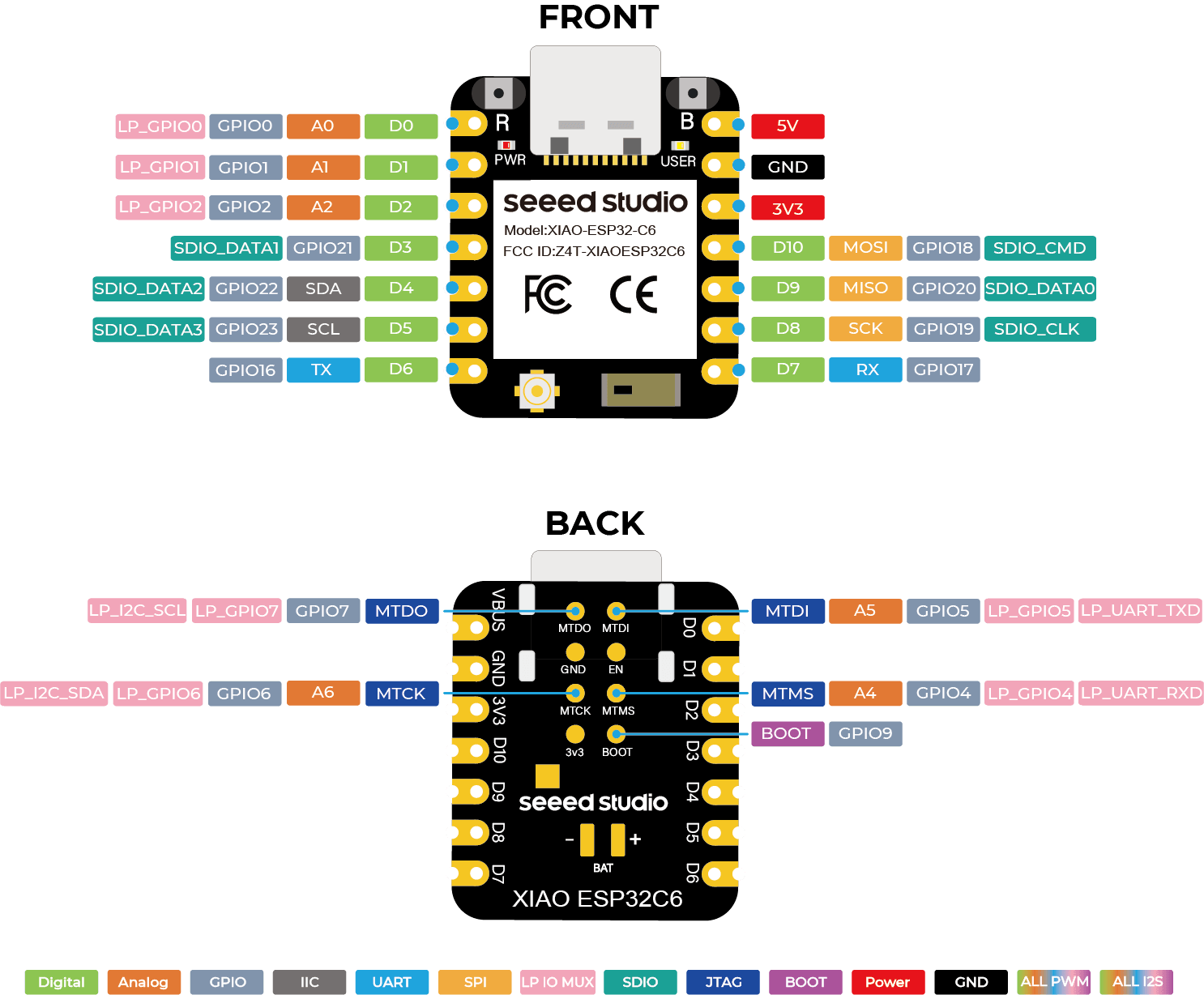
All About XIAO ESP32C6
The XIAO ESP32C6 is a compact, powerful microcontroller with Wi-Fi 6, Bluetooth 5, and Zigbee, making it ideal for IoT and embedded applications. More technical details can be found on the official Seeed Studio Wiki.

| Feature | Description |
|---|---|
| Microcontroller | ESP32-C6 (RISC-V 160MHz CPU) - Efficient processing for embedded applications. |
| Wireless Connectivity | Supports Wi-Fi 6 (802.11ax), Bluetooth 5 (LE), and Zigbee for IoT communication. |
| Operating Voltage | 3.3V logic level, powered via USB-C. |
| GPIO Pins | 8 usable GPIOs (D0-D7), including ADC, I2C, SPI, and UART. |
| PWM & Timers | Capable of hardware PWM for LED control and precision timing. |
| Onboard LED | One built-in user LED on pin D10 for debugging and testing. |
| RGB Matrix Control | Uses GPIO2 with WS2812B LEDs for addressable color control. |
| Programming Methods | Supports Arduino, MicroPython, and ESP-IDF for low-level embedded programming. |
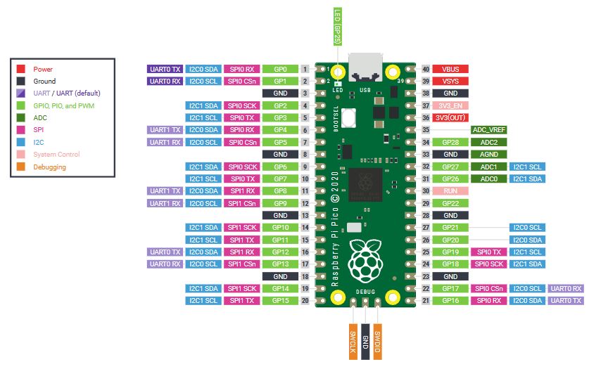
All About Raspberry Pi Pico RP2040
The Raspberry Pi Pico RP2040 is a low-cost, high-performance microcontroller board with a dual-core ARM Cortex-M0+ processor. It is designed for embedded applications and supports MicroPython, C, and Arduino. More technical details can be found on the official Raspberry Pi Documentation.

| Feature | Description |
|---|---|
| Microcontroller | RP2040 (Dual-core ARM Cortex-M0+, 133MHz) - Powerful and efficient for embedded tasks. |
| Memory | 264KB SRAM, external 2MB Flash storage. |
| Operating Voltage | 3.3V logic level, powered via USB micro-B. |
| GPIO Pins | 26 multifunctional GPIOs, including ADC, PWM, SPI, I2C, and UART. |
| PWM & Timers | 16 PWM channels for precise timing and LED control. |
| Onboard LED | One built-in user LED on GPIO25 for debugging and testing. |
| USB Support | Native USB 1.1 host/device functionality. |
| Programming Methods | Supports C/C++, MicroPython, Arduino, and CircuitPython. |
Simulated Wi-Fi Connection in Wokwi
Since Wokwi does not allow actual Wi-Fi connections, this program simulates a Wi-Fi connection process. The red LED blinks while attempting to "connect," and then either the green LED turns on (successful connection) or the red LED stays on (failed connection).
Code Explanation
Below is the Arduino code used to simulate the Wi-Fi connection. The LEDs are controlled based on the simulated connection status.
    #define RED_LED D2    // GPIO for red LED (Wi-Fi failed)
    #define GREEN_LED D3  // GPIO for green LED (Wi-Fi connected)

    void setup() {
        Serial.begin(115200); // Start Serial Monitor for debugging

        pinMode(RED_LED, OUTPUT);   // Set the red LED as an output
        pinMode(GREEN_LED, OUTPUT); // Set the green LED as an output

        digitalWrite(RED_LED, LOW);  // Ensure red LED starts OFF
        digitalWrite(GREEN_LED, LOW); // Ensure green LED starts OFF

        Serial.println("\nSimulating Wi-Fi Connection...");

        // Simulating Wi-Fi connection attempts by blinking the red LED
        for (int i = 0; i < 10; i++) {
            digitalWrite(RED_LED, HIGH); // Turn ON red LED (trying to connect)
            delay(300); // Wait 300ms
            digitalWrite(RED_LED, LOW);  // Turn OFF red LED
            delay(300); // Wait 300ms
            Serial.print("."); // Print progress dots in Serial Monitor
        }

        // Simulate a random connection success or failure
        bool wifiConnected = random(0, 2);  // Randomly pick 0 (fail) or 1 (success)

        if (wifiConnected) {
            Serial.println("\n Simulated Wi-Fi Connected!");

            digitalWrite(GREEN_LED, HIGH);  // Turn ON green LED
            digitalWrite(RED_LED, LOW);     // Turn OFF red LED
        } else {
            Serial.println("\n Simulated Wi-Fi Connection Failed.");

            digitalWrite(GREEN_LED, LOW);   // Turn OFF green LED
            digitalWrite(RED_LED, HIGH);    // Keep red LED ON
        }
    }

    void loop() {
    }
Explanation of Each Section
- LED Pin Definitions: The red LED (D2) indicates a failed connection, while the green LED (D3) indicates a successful connection.
- Setup Function: Initializes the Serial Monitor, sets up the LED pins, and ensures they start in the OFF state.
- Simulated Connection Process: The red LED blinks for a few seconds to represent connection attempts.
- Random Connection Success or Failure: A random number (0 or 1) determines whether the Wi-Fi connection "succeeds" or "fails."
-
Final LED State:
- If connected, the green LED turns ON and the red LED turns OFF.
- If the connection fails, the red LED stays ON.
How to Use in Wokwi
To simulate this in Wokwi, follow these steps:
- Go to Wokwi ESP32 Simulator.
- Add two LEDs:
- Connect the red LED to GPIO D2.
- Connect the green LED to GPIO D3.
- Copy and paste the code into Wokwi.
- Run the simulation and observe the LED behavior.
Credits
The initial setup for this project was inspired by work from Uri Shaked (Urish), the creator of Wokwi. His Wokwi platform has made it easy to test embedded systems in a web-based environment. You can explore more of his amazing projects at Wokwi Project Library.
NeoPixel Animation with Raspberry Pi Pico in Wokwi
In this simulation, the Raspberry Pi Pico controls a NeoPixel ring (WS2812B) using MicroPython. The animation consists of the following effects:
- LEDs move back and forth in different colors.
- After completing two full cycles, all LEDs blink in cyan.
- LEDs then turn solid white for 5 seconds.
- Finally, they fade out smoothly to black.
Code Explanation
Below is the MicroPython code used to create this effect. The animation is controlled based on timing and color logic.
    import time
    from neopixel import Neopixel

    # Configuration for NeoPixel Ring
    NUM_PIXELS = 16  # Number of LEDs in the ring
    PIN = 6  # GPIO pin where the NeoPixel ring is connected
    pixels = Neopixel(NUM_PIXELS, 0, PIN, "GRB")

    # List of Colors (RGB Format)
    colors = [
        (182, 228, 48),   # Yellow-Green
        (66, 209, 224),   # Cyan
        (255, 50, 50),    # Red
        (255, 140, 0),    # Orange
        (128, 0, 255),    # Purple
        (50, 255, 50)     # Green
    ]

    special_color = (66, 209, 224)  # Cyan for blink effect
    fade_color = (255, 255, 255)    # White before fading

    # Initial Settings
    pixel_index = 0
    color_index = 0
    direction = 1  # 1 for forward, -1 for backward
    brightness = 50  # Adjust brightness (0-255)
    cycle_count = 0  # Counts the forward-backward cycles

    def fade_out():
        """ Fades all LEDs to black smoothly """
        for b in range(100, -1, -5):  # Decrease brightness in steps of 5
            pixels.brightness(b)
            pixels.fill(fade_color)
            pixels.show()
            time.sleep(0.05)  # Small delay for smooth fading
        pixels.fill((0, 0, 0))  # Ensure all LEDs are off
        pixels.show()

    while True:
        pixels.brightness(brightness)

        # Set color for current pixel
        pixels.set_pixel(pixel_index, colors[color_index])
        pixels.show()

        # Move pixel in forward or reverse direction
        pixel_index += direction

        # Change direction at the edges
        if pixel_index == NUM_PIXELS - 1 or pixel_index == 0:
            direction *= -1  # Reverse direction
            color_index = (color_index + 1) % len(colors)  # Cycle colors
            cycle_count += 1  # Count cycles

        # After 2 full back-and-forth cycles, trigger special effect
        if cycle_count == 4:
            cycle_count = 0  # Reset cycle counter

            # Blink all LEDs quickly in cyan
            for _ in range(6):
                pixels.fill(special_color)
                pixels.show()
                time.sleep(0.1)
                pixels.fill((0, 0, 0))
                pixels.show()
                time.sleep(0.1)

            # Turn all LEDs solid white for 5 seconds
            pixels.fill(fade_color)
            pixels.show()
            time.sleep(5)

            # Fade to black
            fade_out()

        time.sleep(0.1)  # Delay for smooth animation
Explanation of Each Section
- NeoPixel Configuration: Defines the number of LEDs (16), the GPIO pin (6), and the color format (GRB).
- Back-and-Forth Movement: The LEDs light up one by one, moving forward and then reversing.
- Cycle Counter: Keeps track of how many times the animation completes a full forward and backward movement.
-
Special Effect Trigger: After two cycles:
- All LEDs blink quickly in cyan (6 times).
- Then, they stay solid white for 5 seconds.
- Finally, the fade-out function gradually dims them to black.
- Brightness Control: The brightness is set to 50 at the start, and during the fade-out effect, it decreases in steps of 5.
How to Use in Wokwi
To simulate this in Wokwi, follow these steps:
- Go to Wokwi Raspberry Pi Pico Simulator.
- Add a NeoPixel Ring (WS2812B) and connect it to:
- Data Pin (D6)
- Power (VCC) to 3.3V
- Ground (GND) to GND
- Copy and paste the code into the MicroPython script.
- Run the simulation and observe the effects.
Credits
The initial setup for this project was inspired by work from Uri Shaked (Urish), the creator of Wokwi. His Wokwi platform has made it easy to test embedded systems in a web-based environment. You can explore more of his amazing projects at Wokwi Project Library.
MicroPython vs Arduino: Comparing Embedded Programming Approaches
In this section, we compare the MicroPython and Arduino (C++) approaches for programming microcontrollers. Both have unique advantages and limitations, depending on the application. Below is a table summarizing key differences followed by an explanation of how each language handles operations.
Comparison Table
| Feature | MicroPython | Arduino (C++) |
|---|---|---|
| Language | Python (MicroPython) | C++ (Arduino Framework) |
| Ease of Use | More beginner-friendly, easier syntax | More complex, requires memory management |
| Execution Speed | Slower (interpreted) | Faster (compiled directly to machine code) |
| Memory Usage | Higher (due to Python interpreter overhead) | Lower (more optimized for embedded systems) |
| Hardware Control | Higher-level, easier to implement | Lower-level, gives more control over hardware |
| Libraries | Many built-in Python libraries (simple implementation) | Extensive Arduino library ecosystem (optimized for performance) |
| Real-Time Applications | Not ideal for real-time processing (due to Python overhead) | Better for real-time and timing-critical tasks |
| Best For | IoT, quick prototyping, beginner projects | Robotics, performance-critical applications |
Differences in Code Structure
Although both codes perform similar tasks (controlling LEDs), the way they handle operations is different. Let's look at key differences:
1 Variable Declarations
In MicroPython, variables are dynamically typed:
    NUM_PIXELS = 16  # No need to declare type
    brightness = 50   # Simple variable assignment
In Arduino (C++), variables need explicit data types:
    #define RED_LED D2   // Defining constants
    int brightness = 50; // Explicitly declaring an integer variable
2 Loops & Execution
MicroPython uses `while True:` to run an infinite loop:
    while True:
        pixels.brightness(brightness)
        pixels.show()
        time.sleep(0.1)
Arduino uses `loop()` for continuous execution:
    void loop() {
        digitalWrite(RED_LED, HIGH);
        delay(500);
        digitalWrite(RED_LED, LOW);
        delay(500);
    }
3 Hardware Control & GPIO
In MicroPython, controlling NeoPixels requires a library and is done with:
    pixels.set_pixel(pixel_index, colors[color_index])
    pixels.show()
In Arduino, controlling LEDs is done with:
digitalWrite(RED_LED, HIGH);
My Conclusion
MicroPython is great for rapid prototyping, beginner-friendly development, and IoT projects. Arduino (C++) is better for real-time, performance-critical, and low-level hardware control. The choice depends on the project requirements!
Simulating Air Quality Monitoring with ESP32-C3
Initially, I planned to create a real hardware mini-project, but after experimenting with Wokwi, I realized that a simulated environment provides a quick and efficient way to test embedded programs. This project uses an ESP32-C3 microcontroller and a LED Bar Graph to display live Air Quality Index (AQI) data from my weather station. Instead of physically wiring components, Wokwi allows me to prototype quickly in a virtual space.
The ESP32-C3 connects to Wi-Fi, fetches AQI data via an API request, prints the values to the serial monitor, and displays them using a color-coded LED bar graph.
Why use MicroPython?
Instead of Arduino (C++), I chose MicroPython because:
- It is simpler and more readable than C++
- It allows for faster development in embedded systems
- ESP32 has strong MicroPython support
Components Used
| Component | Description |
|---|---|
| ESP32-C3 Mini | A compact, low-power microcontroller with Wi-Fi & Bluetooth, perfect for IoT projects. ESP32-C3 Datasheet |
| Wokwi LED Bar Graph | A 10-segment LED display used to visualize AQI levels using color codes. Wokwi LED Bar Graph |
1. Connecting to Wi-Fi
The ESP32-C3 connects to Wi-Fi using the network module.
It automatically connects to the Wokwi-GUEST network.
    import network
    import time

    SSID = "Wokwi-GUEST"
    PASSWORD = ""

    wifi = network.WLAN(network.STA_IF)
    wifi.active(True)
    wifi.connect(SSID, PASSWORD)

    print("Connecting to Wi-Fi...")
    while not wifi.isconnected():
        time.sleep(0.5)
    print("Connected! IP Address:", wifi.ifconfig()[0])
2. Fetching AQI Data (API Request)
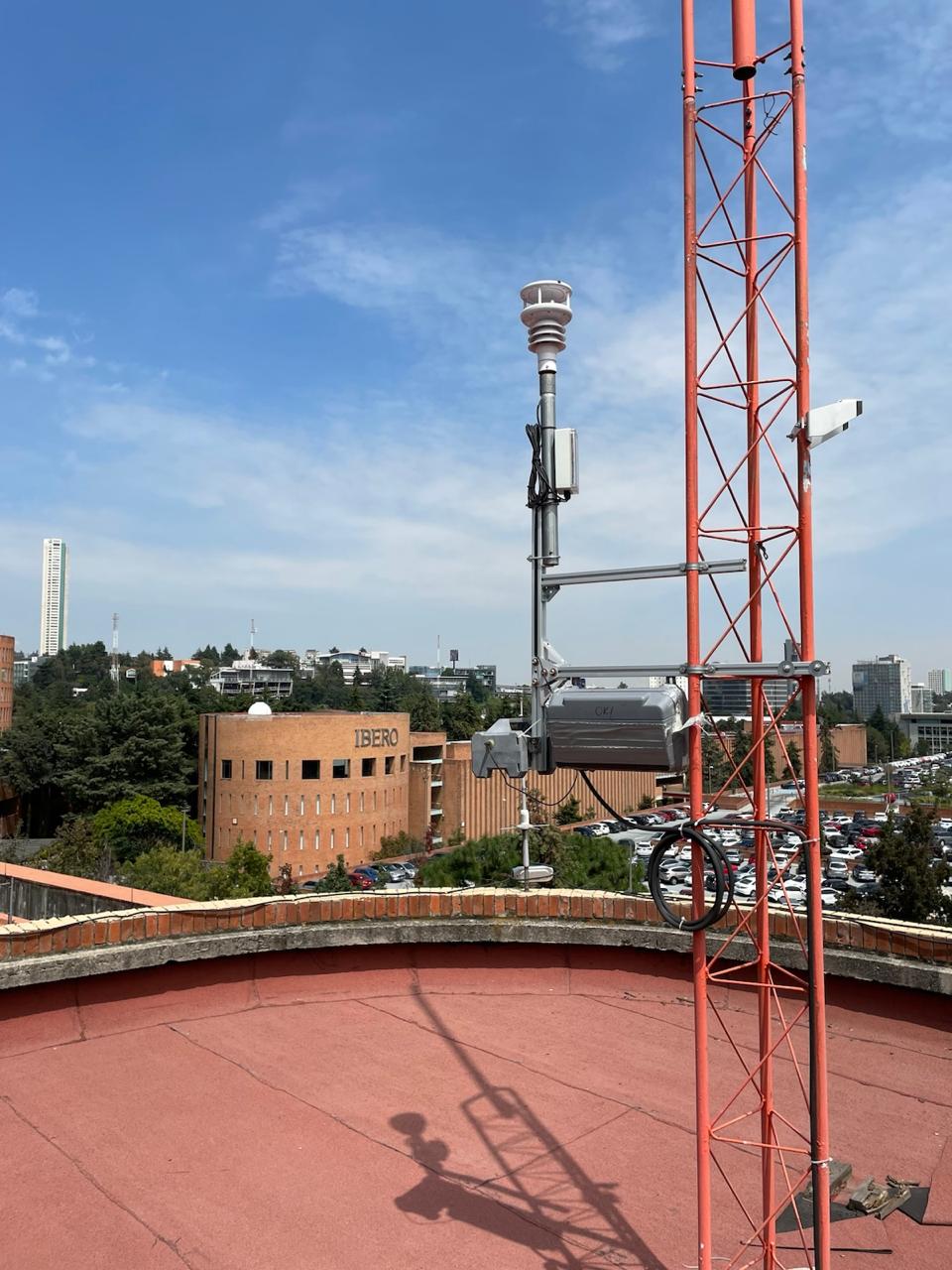
I have a weather station & air quality monitoring system on the roof. This project uses its API to retrieve real-time AQI (Air Quality Index).
The API returns a JSON response, which we parse to extract the latest AQI reading.
    import urequests
    import json

    API_URL = "http://smXXxxXty.sixxXXcmx.com/SmXXxxXXtyAPI/GetData"
    TOKEN = "XXXXxxxXXXxxxxxXXXxXXxxX"
    SENSOR_ID = 1001

    response = urequests.get(f"{API_URL}?token={TOKEN}&idSensor={SENSOR_ID}&dtStart=2025-02-17T08:00:00.000Z&dtEnd=2025-02-17T09:00:00.000Z")
    data = response.json()
    response.close()

    # Extract AQI Value
    last_record = data[-1]
    nested_json = json.loads(last_record["Data"])
    aqi_value = int(nested_json.get("Data", "0"))

    print("Last AQI Value:", aqi_value)
3. Printing AQI Value to Serial Monitor
After fetching the AQI data, we print it in the serial monitor.
print("Last AQI Value:", aqi_value)
4. Displaying AQI with LED Bar Graph
The LED bar graph represents the AQI value using color-coded segments:
| AQI Level | Color | LEDs Lit |
|---|---|---|
| 0 - 50 | Green | LED 1 & 2 |
| 51 - 100 | Yellow | LED 3 & 4 |
| 101 - 150 | Orange | LED 5 & 6 |
| 151 - 200 | Red | LED 7 & 8 |
    from machine import Pin

    LED_PINS = [2, 3, 4, 5, 6, 7, 8, 9]
    leds = [Pin(pin, Pin.OUT) for pin in LED_PINS]

    def update_led_bar(aqi):
        for led in leds:
            led.value(0)

        if 0 <= aqi <= 50:
            leds[0].value(1)
            leds[1].value(1)
        elif 51 <= aqi <= 100:
            leds[2].value(1)
            leds[3].value(1)
        elif 101 <= aqi <= 150:
            leds[4].value(1)
            leds[5].value(1)
        elif 151 <= aqi <= 200:
            leds[6].value(1)
            leds[7].value(1)

    update_led_bar(aqi_value)
Conclusion
This project successfully simulates an IoT air quality monitoring system in Wokwi. It demonstrates how an ESP32-C3 can connect to Wi-Fi, fetch real-world data via an API, and display the results using LEDs.
Downloadables
You can download the full MicroPython script used in this project:
Full MicroPython Code
        import network
        import time
        import urequests
        import json
        from machine import Pin

        # Wi-Fi Configuration
        SSID = "Wokwi-GUEST"
        PASSWORD = ""

        # API Configuration
        API_URL = "http://smaxxXXX.sidxxX.com/SmaxxxXXyAPI/GetData"
        TOKEN = "XXXXxxxXXXXxxxxXXXXxxxx"
        SENSOR_ID = 1001

        # LED Bar Graph Pins
        LED_PINS = [2, 3, 4, 5, 6, 7, 8, 9]
        leds = [Pin(pin, Pin.OUT) for pin in LED_PINS]

        # Connect to Wi-Fi
        wifi = network.WLAN(network.STA_IF)
        wifi.active(True)
        wifi.connect(SSID, PASSWORD)

        print("Connecting to Wi-Fi...")
        while not wifi.isconnected():
            time.sleep(0.5)
        print("Connected! IP Address:", wifi.ifconfig()[0])

        # Fetch AQI Data
        response = urequests.get(f"{API_URL}?token={TOKEN}&idSensor={SENSOR_ID}&dtStart=2025-02-17T08:00:00.000Z&dtEnd=2025-02-17T09:00:00.000Z")
        data = response.json()
        response.close()

        # Extract AQI Value
        last_record = data[-1]
        nested_json = json.loads(last_record["Data"])
        aqi_value = int(nested_json.get("Data", "0"))

        print("Last AQI Value:", aqi_value)

        # Display AQI with LED Bar Graph
        def update_led_bar(aqi):
            for led in leds:
                led.value(0)

            if 0 <= aqi <= 50:
                leds[0].value(1)
                leds[1].value(1)
            elif 51 <= aqi <= 100:
                leds[2].value(1)
                leds[3].value(1)
            elif 101 <= aqi <= 150:
                leds[4].value(1)
                leds[5].value(1)
            elif 151 <= aqi <= 200:
                leds[6].value(1)
                leds[7].value(1)

        update_led_bar(aqi_value)
From Simulation to Physical Implementation
The goal of this project was to take embedded programming beyond simulation and implement it on real hardware. The XIAO ESP32C6 microcontroller and a 6x10 RGB LED matrix were used to visually indicate the Wi-Fi connection status. The LEDs blink red while the device attempts to connect and turn solid green once connected.
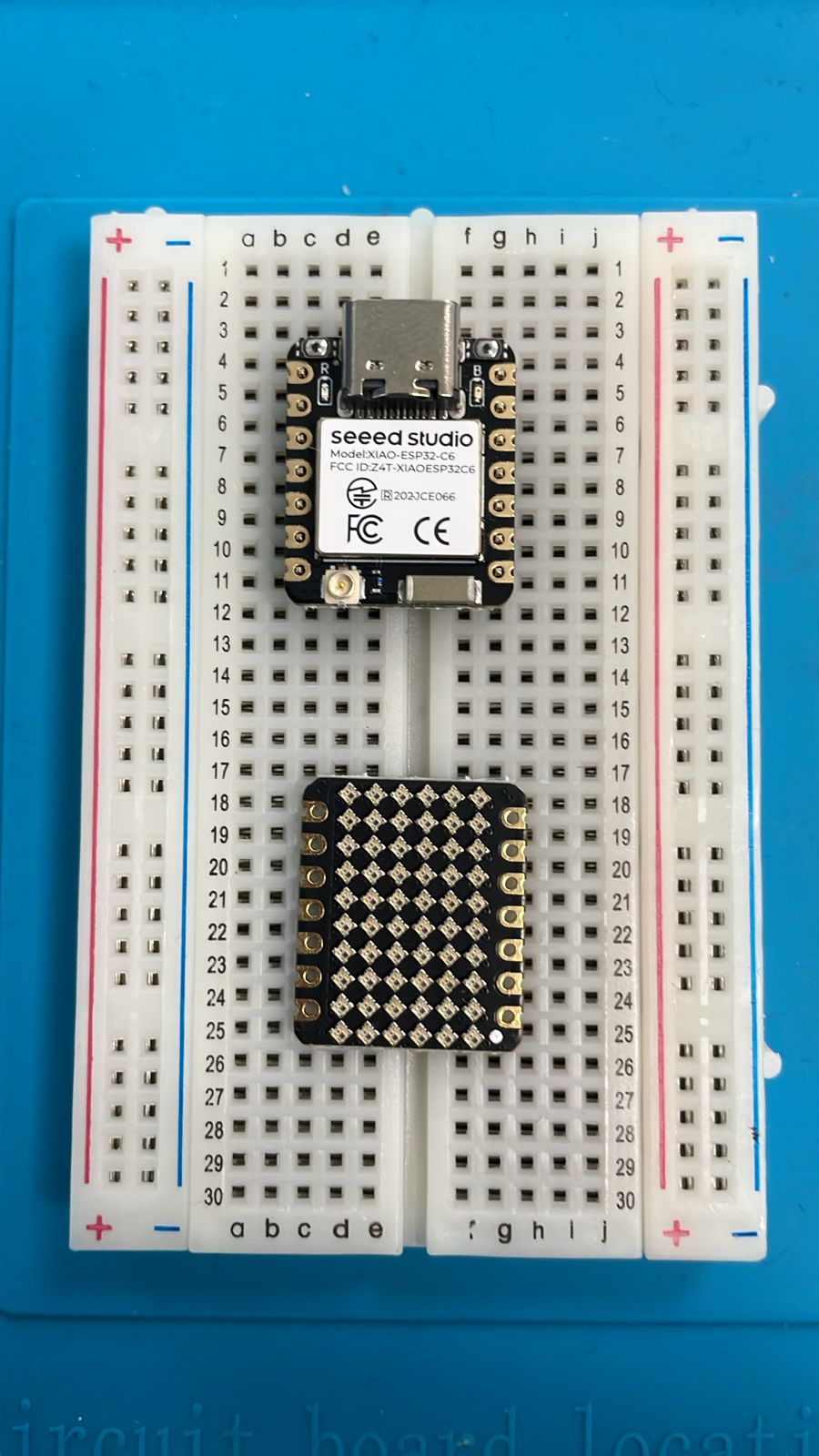
This project demonstrates the transition from software-based simulations, such as those in Wokwi, to real-world embedded systems. By working with physical components, challenges like wiring, power management, and timing accuracy become crucial factors.
Using AI to Generate Embedded Code
Instead of writing the entire program manually, an AI-assisted approach was taken to streamline the development process. By providing a detailed prompt specifying the behavior of the system, AI was able to generate structured, optimized code. This approach allowed for multiple iterations and refinements, ensuring that the final result functioned as intended.
AI was particularly useful in structuring the logic for handling Wi-Fi connectivity and LED control efficiently. The generated code was further modified and tested to ensure smooth operation.
AI-Generated Prompt
The following prompt was used to generate the final code using AI. It specifies the required behavior, logic, and optimization steps.
    "Write an Arduino sketch for a XIAO ESP32C6 that connects to Wi-Fi and controls a 6x10 RGB LED matrix using the Adafruit NeoPixel library. Follow these requirements:

    1 Wi-Fi Connection:
    - Connect to Wi-Fi using SSID: "Primavera25"
    - Password: "Ib3r02025ui@"
    - Print Wi-Fi status in the serial monitor.

    2 RGB LED Matrix (60 LEDs, WS2812B type):
    - Uses GPIO2 (D0) for data input.
    - Set brightness to 50% (127 on a scale of 0-255).
    - Adafruit NeoPixel library must be used.
    - Ensure the matrix initializes correctly before setting colors.

    3 LED Behavior:
    - While connecting to Wi-Fi:
        - Blink RED every 300ms.
        - Continue blinking even if the connection happens fast.
        - Minimum 3 seconds of red blinking before any green LED appears.
    - If connected successfully:
        - Turn all LEDs solid GREEN after 3 seconds of blinking.
    - If the connection fails:
        - Keep blinking RED indefinitely.

    4 Optimize the Code:
    - Ensure proper delays to avoid flickering.
    - Add clear comments explaining each step.
    - Optimize loop logic to avoid unnecessary delays.

    Generate a clean and optimized Arduino code snippet that follows these exact steps."
Final Code: Wi-Fi Status RGB Matrix
The following code connects the XIAO ESP32C6 to Wi-Fi and visually indicates its status using a 6x10 RGB matrix. The LED matrix blinks red while attempting to connect, guarantees at least 3 seconds of blinking even if Wi-Fi connects fast, and turns solid green when connected. If Wi-Fi fails, it continues blinking red indefinitely.
        #include <WiFi.h>
        #include <Adafruit_NeoPixel.h>

        const char* ssid = "Primavera25";
        const char* password = "Ib3r02025ui@";

        #define MATRIX_PIN D0  // RGB Matrix Data Pin (D0 = GPIO2)
        #define NUM_LEDS 60   // 6x10 Matrix = 60 LEDs
        #define BRIGHTNESS 127  // 50% brightness (0-255)

        Adafruit_NeoPixel matrix(NUM_LEDS, MATRIX_PIN, NEO_GRB + NEO_KHZ800);

        void setup() {
            Serial.begin(115200);
            Serial.println("\nStarting...");

            // Initialize NeoPixel and set brightness
            matrix.begin();
            matrix.setBrightness(BRIGHTNESS);
            matrix.clear();
            matrix.show();
            delay(100);

            Serial.println("Connecting to Wi-Fi...");
            WiFi.begin(ssid, password);

            int attempt = 0;
            unsigned long startTime = millis();

            while (WiFi.status() != WL_CONNECTED && attempt < 20) {
                Serial.print(".");

                // Blink RED while connecting
                for (int i = 0; i < NUM_LEDS; i++) {
                    matrix.setPixelColor(i, matrix.Color(255, 0, 0));
                }
                matrix.show();
                delay(300);

                matrix.clear();
                matrix.show();
                delay(300);

                attempt++;
            }

            // Ensure RED blinking lasts at least 3 seconds
            while (millis() - startTime < 3000) {
                for (int i = 0; i < NUM_LEDS; i++) {
                    matrix.setPixelColor(i, matrix.Color(255, 0, 0));
                }
                matrix.show();
                delay(300);

                matrix.clear();
                matrix.show();
                delay(300);
            }

            if (WiFi.status() == WL_CONNECTED) {
                Serial.println("\nConnected to Wi-Fi!");
                Serial.print("IP Address: ");
                Serial.println(WiFi.localIP());

                // Solid GREEN when connected
                for (int i = 0; i < NUM_LEDS; i++) {
                    matrix.setPixelColor(i, matrix.Color(0, 255, 0));
                }
                matrix.show();
            } else {
                Serial.println("\nFailed to connect.");
                // Keep blinking RED if Wi-Fi fails
                while (1) {
                    for (int i = 0; i < NUM_LEDS; i++) {
                        matrix.setPixelColor(i, matrix.Color(255, 0, 0));
                    }
                    matrix.show();
                    delay(300);

                    matrix.clear();
                    matrix.show();
                    delay(300);
                }
            }
        }

        void loop() {
            // Nothing needed in loop
        }
Video Demonstration
The videos below shows the RGB matrix transitioning from Wi-Fi Not Connected (blinking red) to Connected (solid green).