Carved Gourd Bot
The team is composed by two technology’s social impact keens with engineerial background.
Thus, for this group work we look for some specific problematic that we can contribute to.
Thus, we focus on artisans crafts and develop a machine that could support hand-made creation and
provide some geometric guidelines to hand-made carved grouds.
THE JOURNEY TO FABRICATE A CARVED GOURD BOT
SELECTING THE MACHINE TO DESIGN
 We reviewed different options, to work with, and decide to ensemble a machine that could draw some geometric lines on
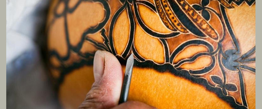
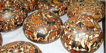
Mates Burilados,
Peruvians handmade traditional crafts. These crafts are produced by carving gourds with exceptionally detailed
representations of rural communities’ life. The gourds grow at the Peruvian coast, and they are sold as touristic
handicraft. The productive process is complex, there are no patterns, thus, every product is unique, each output
relies on artisan abilities and inspiration. Hence, there is a limitation to increase their production, which curtail
their growth.
(Barreras de exportación de mates burilados en
el anexo de Cochas Chico, Huancayo en el año 2020)
We reviewed different options, to work with, and decide to ensemble a machine that could draw some geometric lines on
Mates Burilados,
Peruvians handmade traditional crafts. These crafts are produced by carving gourds with exceptionally detailed
representations of rural communities’ life. The gourds grow at the Peruvian coast, and they are sold as touristic
handicraft. The productive process is complex, there are no patterns, thus, every product is unique, each output
relies on artisan abilities and inspiration. Hence, there is a limitation to increase their production, which curtail
their growth.
(Barreras de exportación de mates burilados en
el anexo de Cochas Chico, Huancayo en el año 2020)
Thus, we though that some carved guidelines could be produce with a machine. We search for examples,
or similar machines that could draw on geometry irregular surfaces. Our instructor suggested to look for machines
that draw lines on eggs, also known as egg-bots. We’ve got some example that could be useful, even some commercial
options.
BENCHMARKING PROCESS
Sphere-O-Bot a CNC machine design by JJRobots to draw basic figures over eggs. The key components in this design (as you can see in the picture) are:
- 2x 1.8deg HIGH QUALITY NEMA 17 Stepper motors (40mm length) (4.4Kg/cm torque)
- 1x SG90 servo
- DEVIA Robotics Control Board
- 2x A4988 Stepper motor drivers
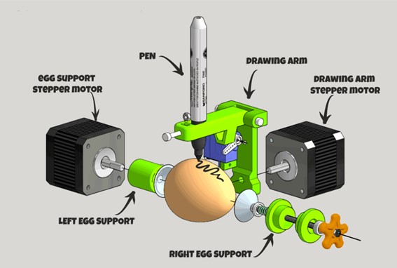
The barrier with this design was the use of DEVIA Board, because is not available locally. However, we decide to test the framework’s design.
(This is the design shared by the web site)
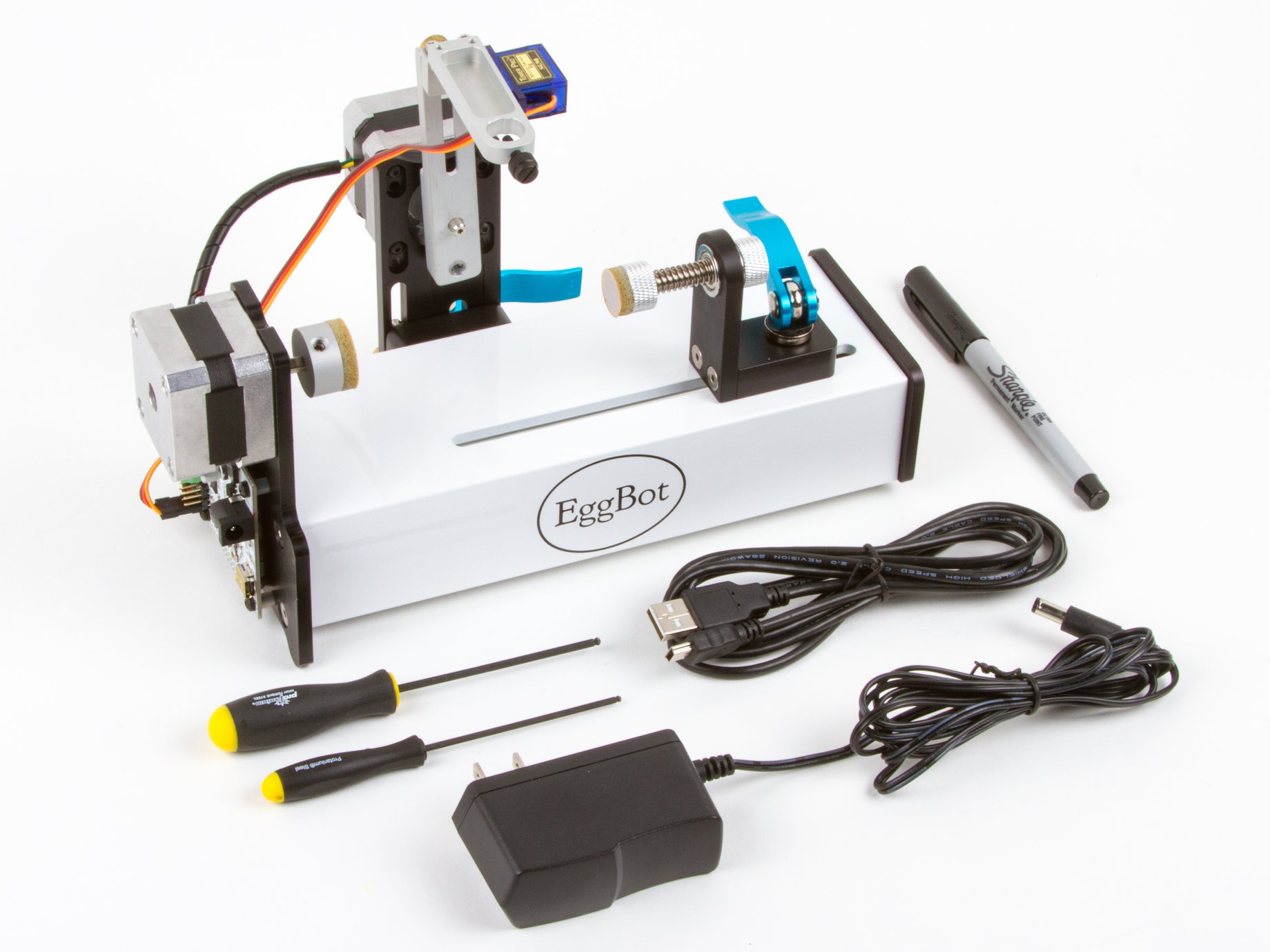
We also found, The EggBot Pro, a commercial device that uses a main framework of solid aluminium. This product allows to decorate different objects (that could be bigger that an egg). Also controlled by high-torque precision stepping motors, with pen lift mechanism is a quiet and reliable servo motor. They use 16× microstepping to give a resolution of 3200 steps/revolution in both axes. We noticed that this design uses NEMA 17 Stepper Motor Mounting Brackets. Similar to the ones used in some 3D printer models. Thus, we decided to include them in our main frame design, instead of printing them, and ensure stability.
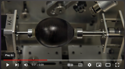
Engraving Easter Eggs with the Egg Laser , we found this variation of the egg-bot that cotains a laser to engrave eggs, created by untitled.house and that you can find in its Youtube channel. Instead of a pen, it uses a water cooled 1 W laser diode. In this case the main frame is made of aluminium. And we believe that could be a second stage of our project, because we will need to import the laser diode and test it with a different main frame and components.
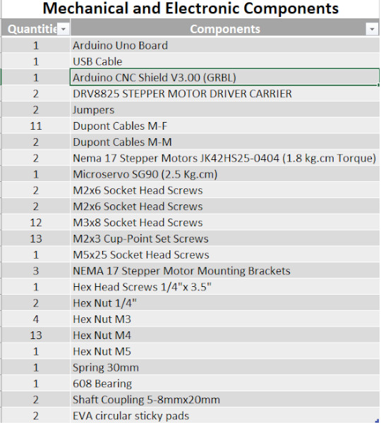
MECHANICAL AND ELECTRONIC COMPONENTS
For this asignment we are allowed to use commercial devices, with our instructor support we select commercial boards
and devices that we can use for this machine design. In this case, to build this XYZ Axis Plotter (CNC machine),
all the mechanical and electronic devices that you’ll need to create this bot are:

MECHANICAL DESIGN
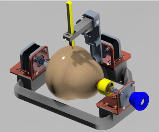
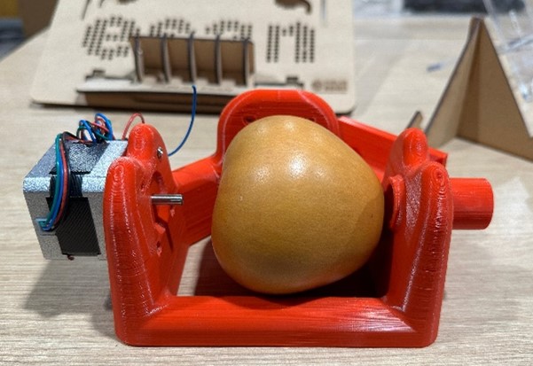
This is the final result our Carved Groud Bot. However, we have a few design iterations base on other projects that
develop egg-drawing CNCs.
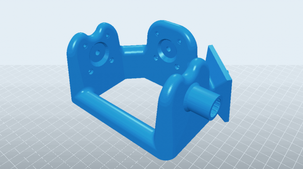
Taking the Sphere-O-Bot, as a reference,
we develop a first design, following similar main frame. However, we discarded this design due to:
- The main frame has horizontal holes to hold the safth, but the printing process requiered supports. This cause rough printing surface, which create problems with screws’ alignment.
- Due to main frame dimensions the printing process was almost 4 hours, and this could become a problem during future iterations (include some improvements), and we had a constrained timeline.
 This is the 4 hour printing test from Sphere-O-Bot.
We look for other possibilities, and base on The EggBot Pro,
a commercial device that uses a solid aluminium main frame we notice the advantages of using commercial brackets for the NEMA 17 stepper motors.
This selection generate a design improvement.
This is the 4 hour printing test from Sphere-O-Bot.
We look for other possibilities, and base on The EggBot Pro,
a commercial device that uses a solid aluminium main frame we notice the advantages of using commercial brackets for the NEMA 17 stepper motors.
This selection generate a design improvement.The use of NEMA 17 stepper motors brackets generated the following design improvement:
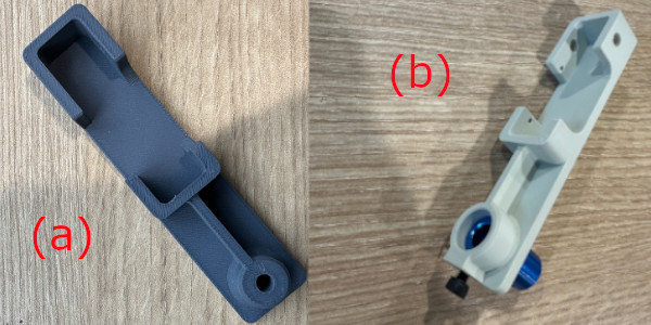
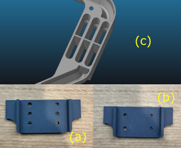
- Y Axis Arm: We redesigned the mounting hole to the stepper motor. Fig (a) shows the original dimension that it was suppose to fit into the stepper motor shaft. However, it was not possible to couple the piece with the stepper motor’s shaft. This because the stepper motor shaft did not have a notch that could provide a better adjustment. Thus, we change the mounting hole diameter (Fig b), in order to use a commercial Shaft Coupling (5-8mmx20mm). This product provides fixation holes that allows to fasten the shaft and the axis arm with set screws.
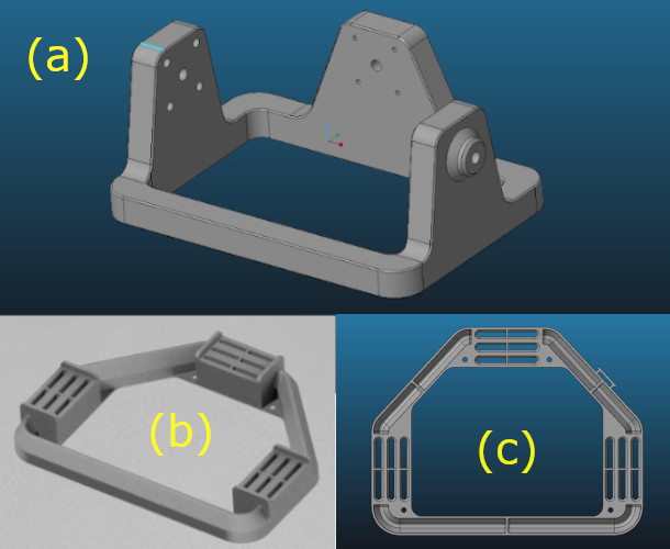
- Changes within the original main frame (fig a):
- Stepper motors mounting holes changed from horizontal to vertical position (fig b). This because we decided to use stepper motor commercial brackets. Thus, we could ensure fastening.
- Other advantage relies on reducing printing time, due to volume reduction and to turn a solid 3D printed geometry to a shelled model (fig c).
- We decide also to change the regular flat top surface to a 60° angled surface. This was to avoid the of supports.
- NEMA 17’s brackets mounting holes: We tested with different rows quantities with 2 (fig a) and 3 (fig b). However, this kind of adjustment is complex for assembling. Thus, the final design (fig c) changed to slots.
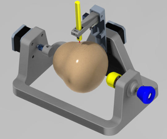
The final Mechanical design
Once the components and mechanical design changes were done, we attempt a first assembly. Thus, we describe key mechanical parts:
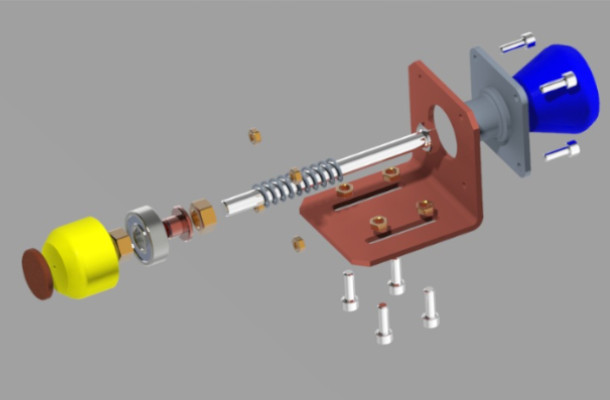
- X Axis press and turn mechanism: This allows gourd adjustment. The design bring the possibility to increase gourd sizes from 8 to 10 cm. Also includes a 608 bearing, that facilitates rotation.
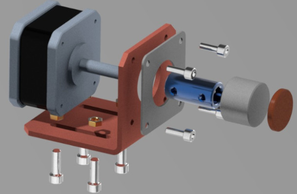
- X Axis Actuator: This render shows assembles of the bracket to the main frame and the stepper motor to the bracket. Also how the shaft coupling is adjusted and the inclusion of a holder-top. This final part receive the EVA circular sticky pads, that would sustain the gourd.
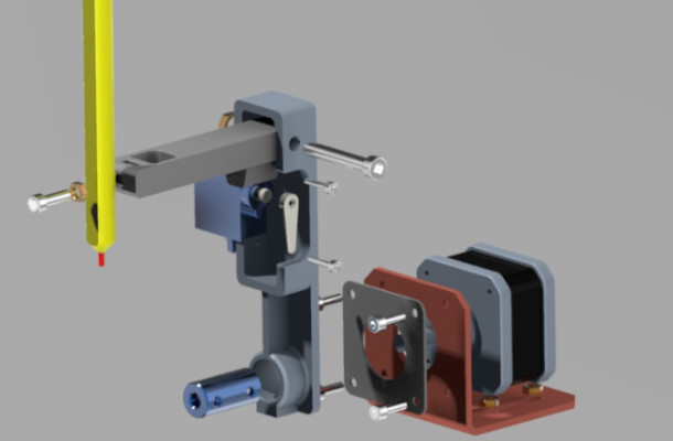
- Y-Z Axes: This render shows assembles of the drawing arm.
For this assignment we are using:
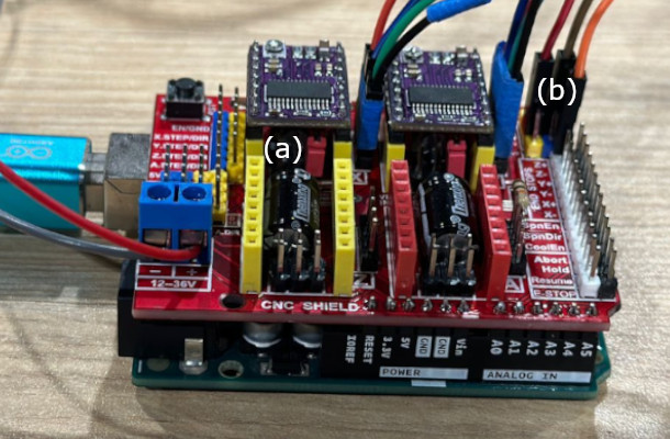
- A Commercial CNC-Shield V3 (GRBL) compatible with Arduino Uno. This is one of the most used to support CNC machines.
- We used DRV8825 stepper motor driver carrier. This device provides a maximun current of 2.5A and a allows 1/32 microstepping, that is very useful to work with CNC that will generate drawings, because it provides better resolution. We configurated both stepper motors driver to 1/16 microsteps, thus we included a jumper (fig a) on MOODE2 (M2) pin.
- Additionally, we followed Elliot Williams hacking solution to control a servomotor for Z Axis function. Thus, we use Z+ Axis -End Stop pin (fig b) to connect it, this would also need a hacking process for the GRBL stored in the Arduino One.
Programming Set-Up
To control de CNC we are using 3 key programs:
- GRBL with a coding variation elaborated by Elliot Williams. You can download the library
here. We describe the steps
that we applied to install the Arduino Uno’s GRBL variant.
- Download the zip file from Github repository.
- Locate grbl folder (fig a).
- Copy the grbl folder to Arduino library folder.
- Open the Arduino IDE.
- Open the GRBL by going to File option in the general menu, then select examples. A drop menu will be available and we have to select grbl and grblUpload (fig b).
- Upload the grbl to Arduino IDE by pressing run option.
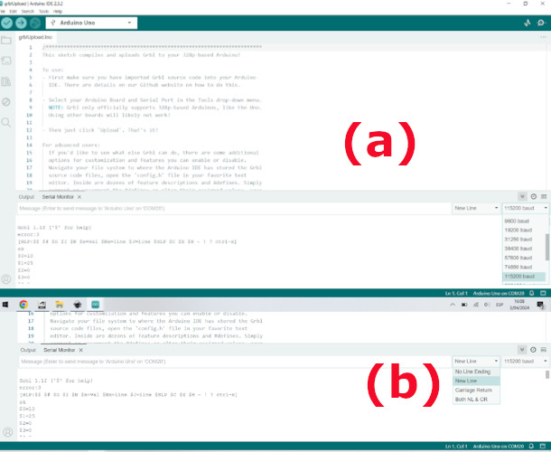
- Then we need to test that the GRBL is running. So we need to open the Arduino serial monitor.
- Then we need to select 115200 Bauds (Fig a) and select “New Line” option (Fig b).
- You can test if everything runs ok by sending a $$ command.
- Then you will get the machine parameters.

- Inkscape for G-Code Generation. Like suggested by
Elliot Williams, we follow his
instructions on how to generate G-Code using Inkscape and also complement the information with
Ignacio Rojas YouTube Channel.
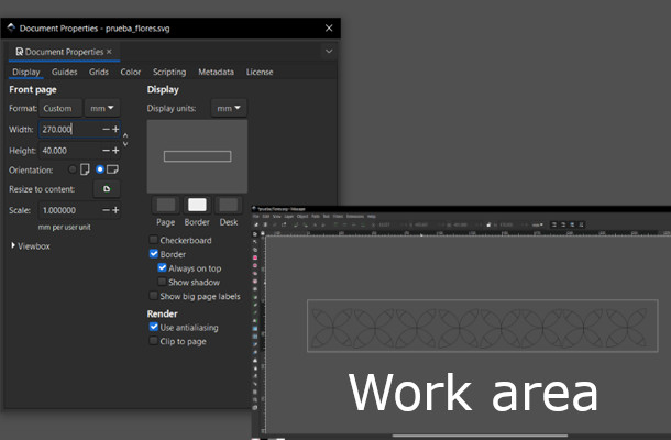
- First you need to set up the graphic dimensions, thus, you need to set them them into the gourd. We assume a cylindrical shaped as a geometry, and mesure the perimeter and height that we will manage to generate the drawing. We stablish a 270x40mm area.
- Then, we set the 270x40mm area into a new document properties.
- Then you need to generate the drawing, you can use part or the total working area. The figure bellow shows the process.
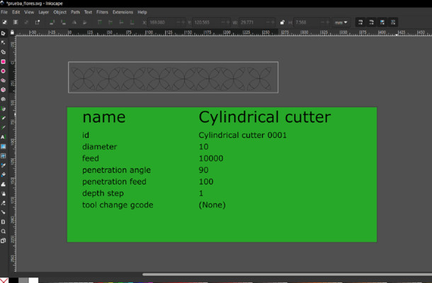
- We used Gcodetools extension within Inkscape to generate de G-Code. For this process you need to:
- From the Gcodetools Menu select the option “Tools library” (fig a)
- Then a option window will open
- Here you need to select the kind of tool type, in our case we select cylinder (Fig b).
- This process brings you the tool features (a green box will appear in your screen). Here it is recommendable to change the feed feature (it will appear with 400) to accelerate the three axes movements.
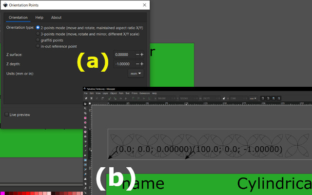
- Then we need to set orientation points (XY coordinates origin). Select extensions > Gcodetools>Orientation Points.
- A new option window will open, and you only need to click apply (maintain default option) (Fig a).
- The orientation coordinates will appear in the bottom left point of origin (Fig b).
- You need to ensure that your images are grouped and that you turn them into vectors.
- Then to generate the GCode first we select the images then, go to extentions>Gcodetools>Path to Gcode
- A new option window will open (Fig a) < select preferences and here we must change “Z safe height” option (height that will achieve Z axis tool to change position). By default, appears 5mm, we must increase this number being sure that it needs to be a positive number. You have to acknowledge that this number will affect drawing time. So we set it up to 1mm (Fig b).
- In preferences option you have also to select the folder to storage Gcode files
- Then you need to return to Path to Gcode option and click apply.
- A .ngc extension file will be created.


- Universal Gcode Sender. This program connects the computer with Arduino GRBL. You need to download the program
from here.
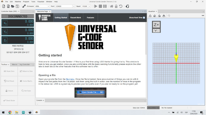
- The program is available in GitHub, two options are available. The UGS classic and UGS Platform. In our case use the last one because it runs without installation. Download the files and go to bin execute ugsplatform64.exe
- The UGS program will open and to set up the connection we need to select 115200 Bauds, port, and firmware (those options are located down the main menu).
- Then we need press the Connect or Disconnect button.
- We need to configure the GRBL parameters. Thus, send $$ command.
- With that command the program will echo a list of parameters. Between those, we need to focus on the ones labelled as $100 to $132 parameters (see the following picture)
- To send our drawing we change only six (06) specific parameters:
- $100: X Axis Travel Resolution: 11.85 step/mm (We devided 3200 microsteps / 270mm).
- $101: Y Axis Travel Resolution: 12 step/mm. Our Y axis has 40° movement (480 microsteps to cover 40 mm length).
- $110: X Axis Maximum Rate: 20,000 mm/min (we test different velocities and set it more efficiently).
- $111: Y Axis Maximum Rate: 20,000 mm/min (we test different velocities and set it more efficiently).
- $120: X Axis acceleration – 1000 mm/sec2.
- S121: Y Axis acceleration – 1000 mm/sec2.

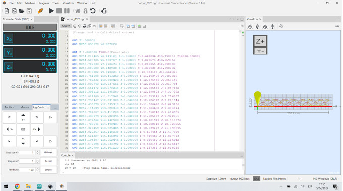
- Then open the .ngc extension file created previously.
- Then click play button. The CNC will start drawing, like shown down below.
FILES
Students
Continuing Students
New Students
Instructors