Review the safety data sheets for each of your molding and casting materials
Make and compare test casts with each of them compare mold making processes.
Individual assignment:
design a mold around the process you'll be using,
produce it with a smooth surface finish that
does not show the production process toolpath,
and use it to cast parts
Molding refers to the process of shaping a material, typically a soft or semi-liquid substance, into a specific form
or shape using a mold. The material could be anything from plastic and metal to glass and ceramics. The molding
process can be achieved through various techniques, such as injection molding, compression molding,
blow molding, and rotational molding.
At its core, mold making involves the creation of a negative space or cavity that perfectly mirrors the desired
object's shape. This cavity then serves as a template to produce multiple copies of the object, whether it be in
plastic, metal, or any other material.
Applications:
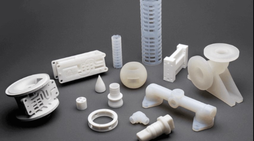
Molding is a versatile manufacturing process used across various industries, including:
Automotive: Producing various parts, from small components to large body panels.
Electronics: Creating housings and components for electronic devices.
Medical Devices: Manufacturing medical equipment and implants.
Consumer Goods: Making a wide range of products, from toys to household items.
Silicone Molding
Silicone molding, also known as silicone rubber molding, is a type of molding process that uses silicone rubber as
the molding material. This method is widely used for creating flexible and durable parts, often for prototypes,
low-volume production, and intricate designs that are
difficult to achieve with other molding processes.
Design
This week I was waiting to work on the button keycaps for my final project. As the week's went by small pieces of my
game board started to
fit together like a jigsaw puzzle. I had been wondering how I could make custom buttons for my board and this week
answered that question for me
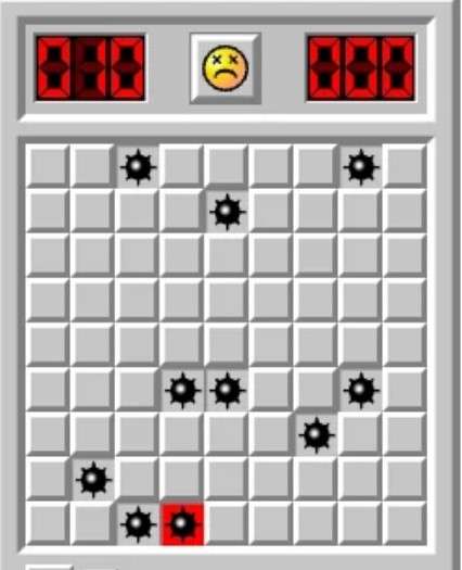
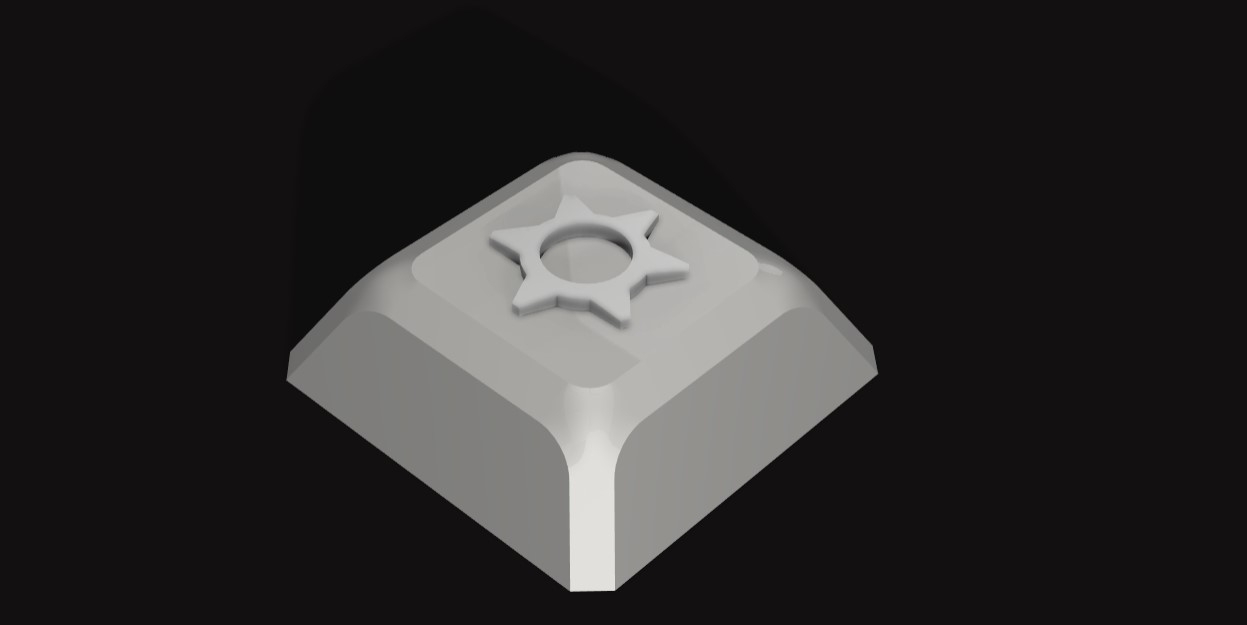
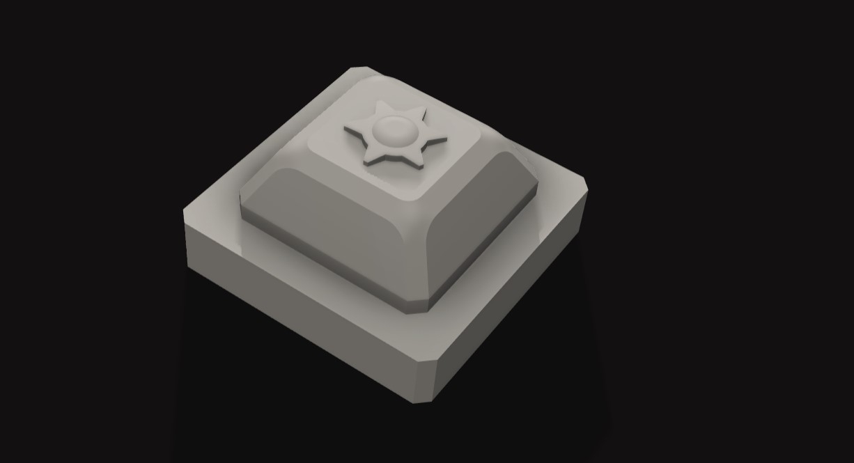
I wanted to make the keycaps to retain the feel of the tiles from the computer game but also add some small
details to bring it into the present era and add something of my own. Also the design may turn out a little bland in
real life without some changes. We probably will see how they may look like once I make the caps.
I referred to some videos about keycaps molding to understand how the shell of the cap was made to get a general
idea on how to design it.
I would have to make a two part mold to make the keycaps as i needed it to hollow. I can also keep the parting line
at the edge of the caps to hide it. The part required for the final product will be in between the molds to create
the shell.
I also wanted the caps to be slightly bigger than normal keyboard keycaps as they are being customized for the game
.
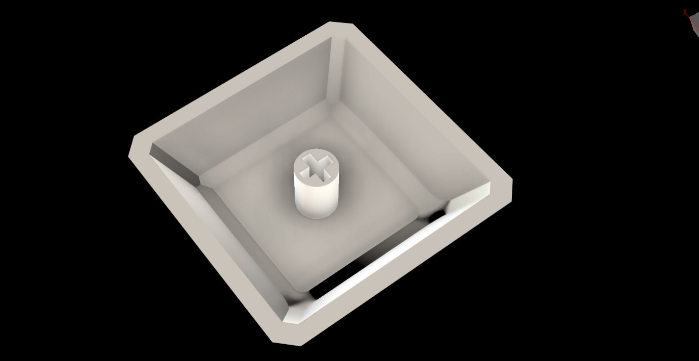
Another challenge was figuring out how to make the shaft on which the keys will sit.
CAD Modelling
We were given a brief overview abt the CAM
process and how to simulate toolpaths in Fusion 360. The first step was to make the model of the design.
The cap design was made and an svg of a mine was imported and made to be a slight projection
from the the surface to add a detail to the key.
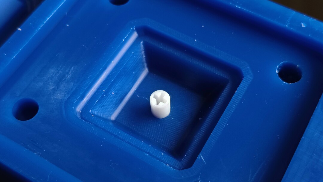
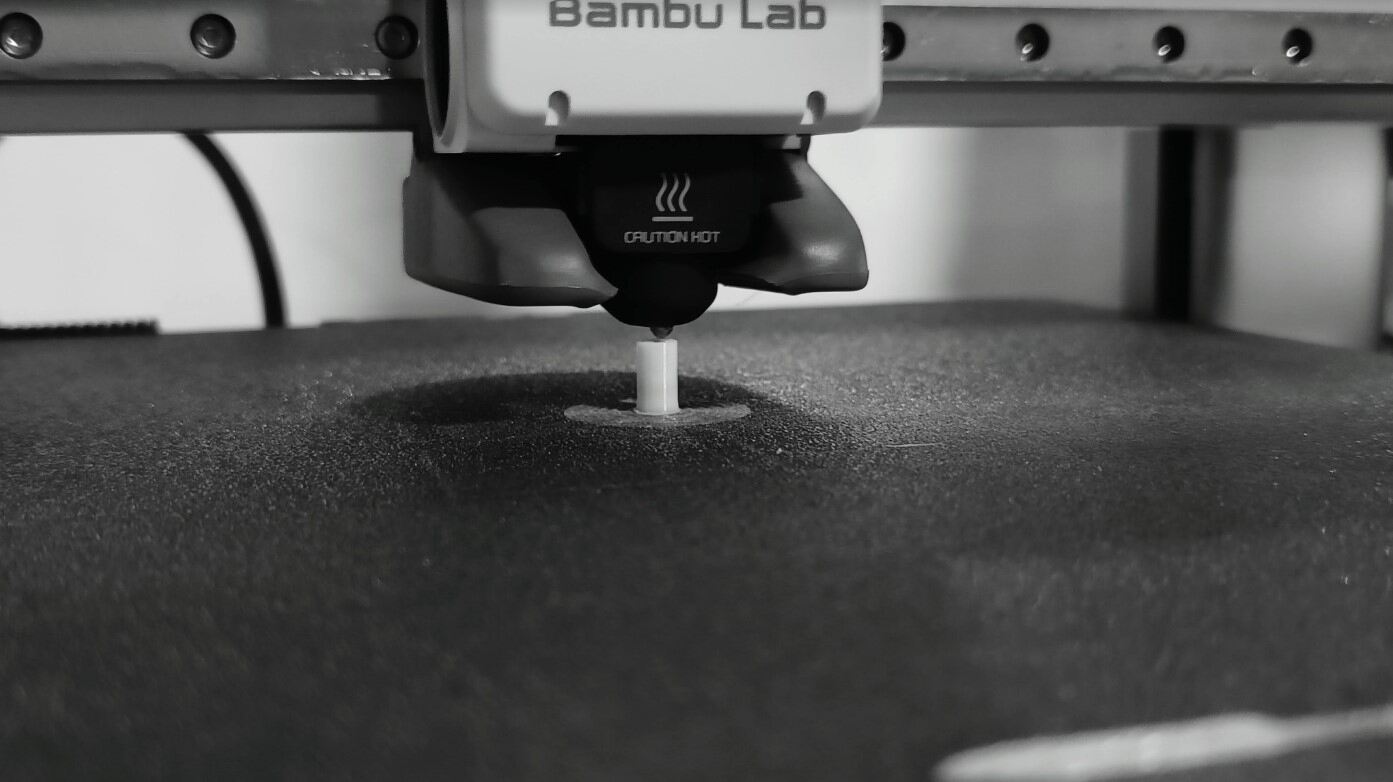
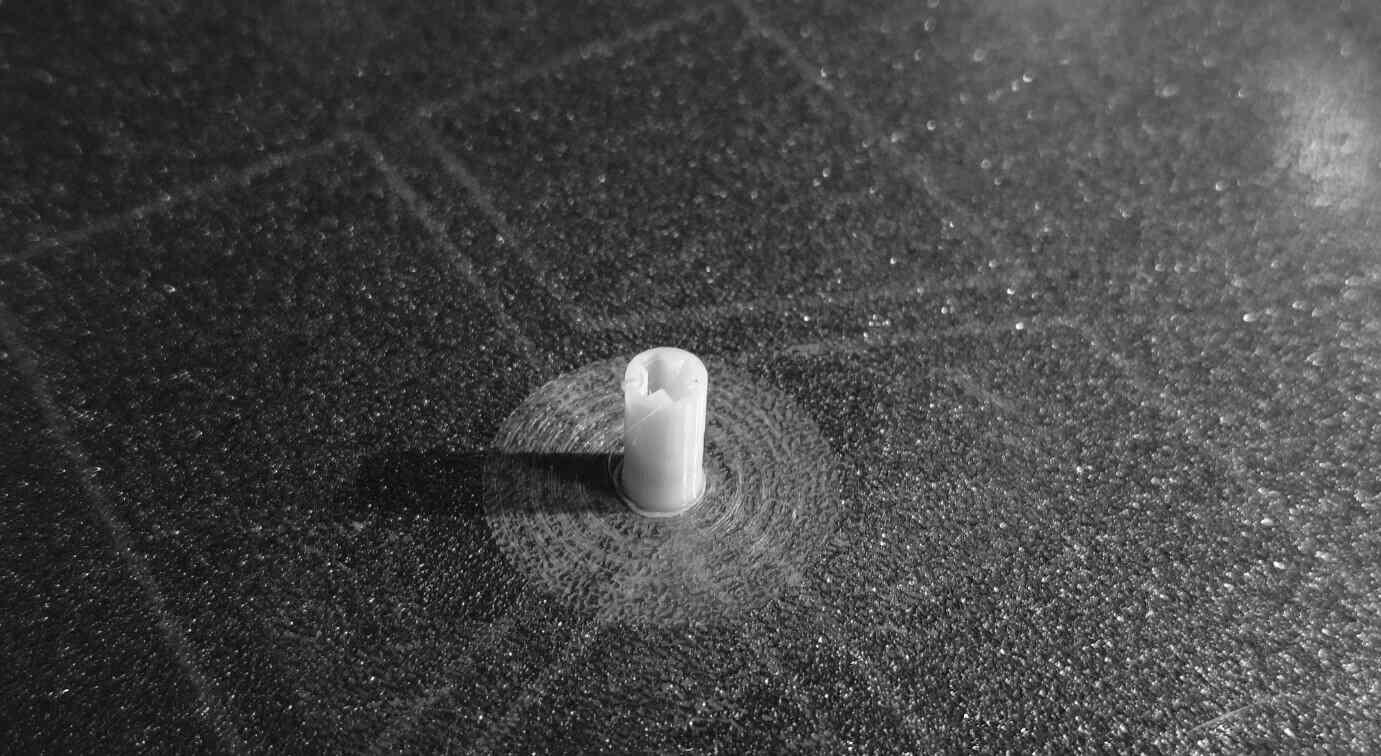
The shaft had to be designed and sent for 3D printing separately as it could not be filled using the
machine with the tools available to us.
The print was done using a 2mm nozzle and it fit well into the clicky switches.
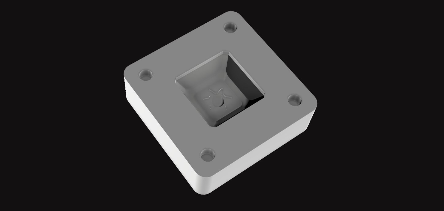
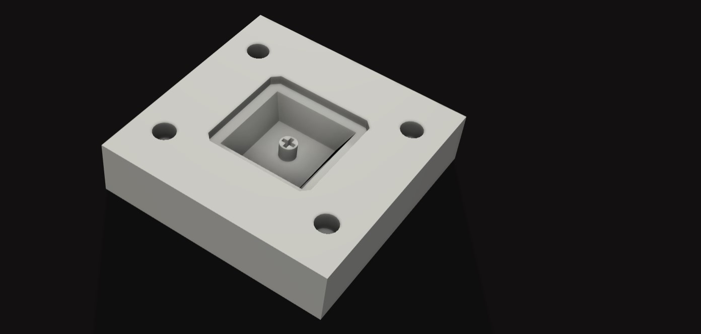
The process that took the most time for me was figuring out the positive molds for the top part and
the inside part. There needed to be steps on the mold to help it sit better. But this part was very confusing
to me as we were making the positive mold and not the negative. So it was a tough job to visualise how it would
fit together.
After a lot of iterations , it came together with the help from my instructors saheen and mufeed.
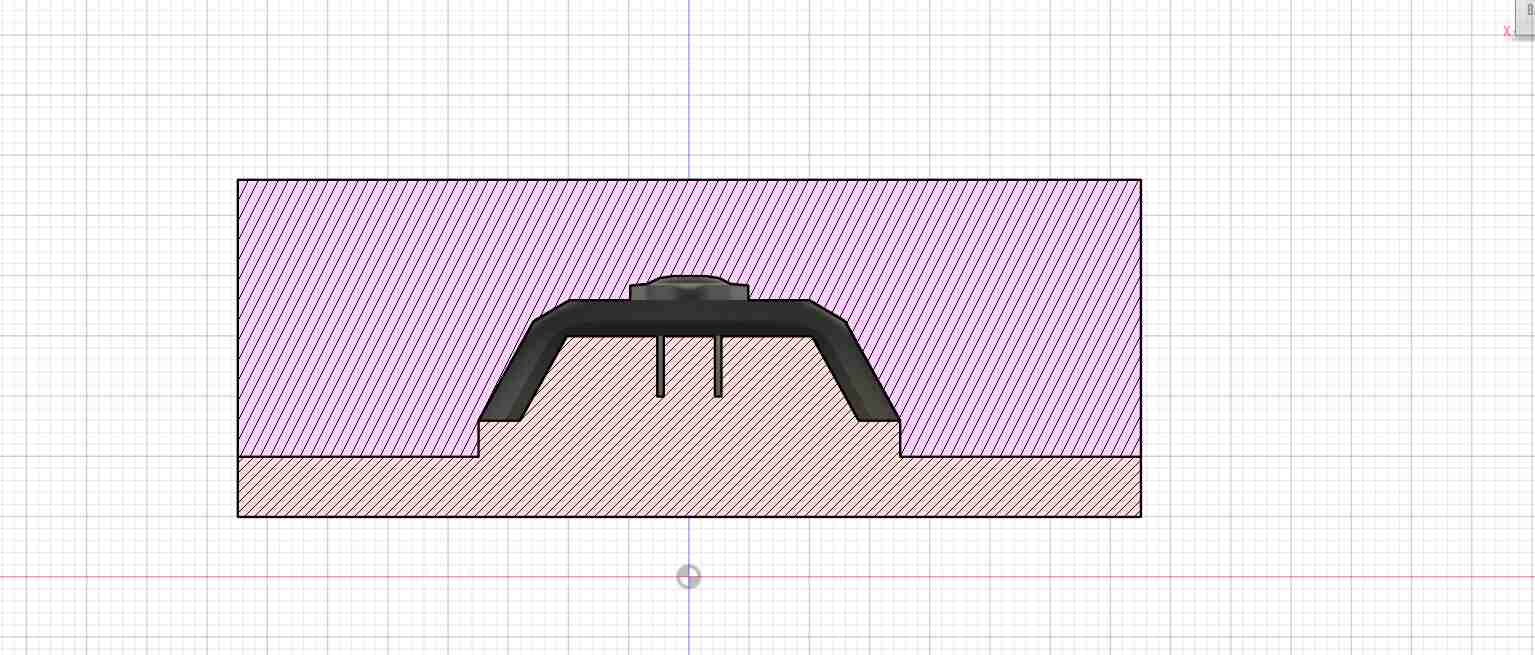
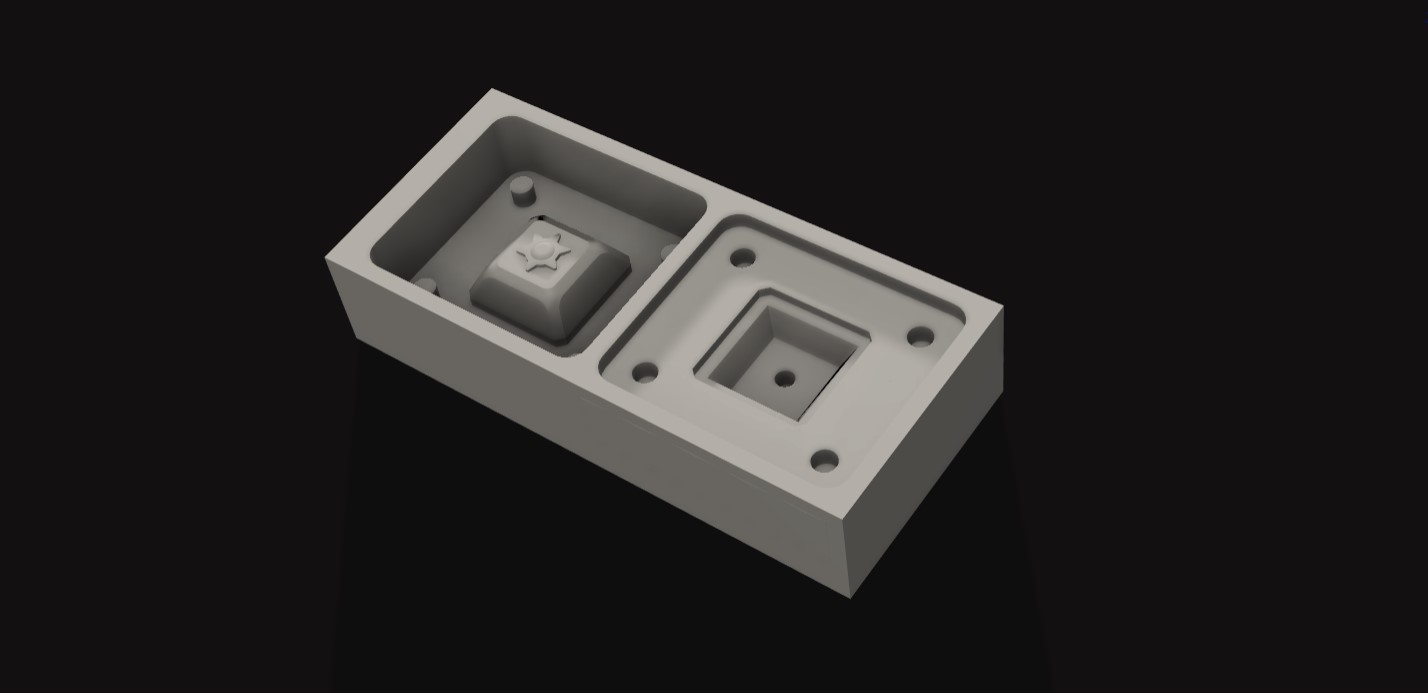
To help the visualisation process and to analyse how the molds will sit together, a block was extruded and
with the boolean function a negative of the molds were made and then fit together. This showed us whenever
there was a mismatch in the steps or the shell. It definitely took a big portion of my
time to do this
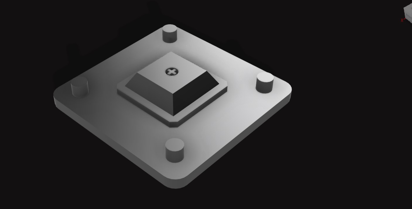
Registeration pins were added to the design. Registeration pins help us place the molds and lock them exactly in
their positions
A bounding box representing the workpiece was made as we were given limited material to use.
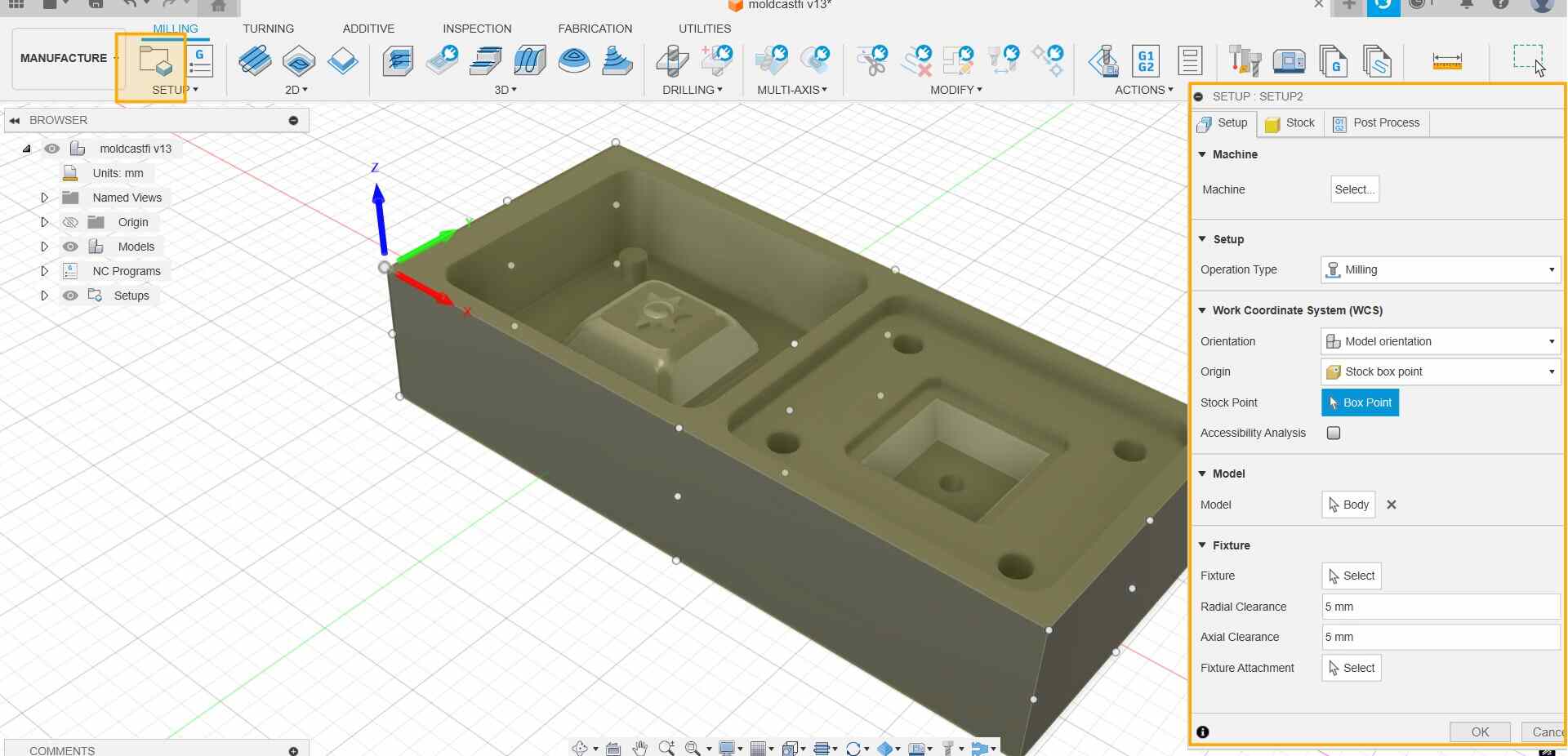
CAM
Here we can give the values of our tools , the stock size and the type of subtractive process that will
be used to remove the material with different tools.
A tool Library had to be imported to know and use the tools we had available in our lab.
First we have to setup our workpiece to set the correct origin, orientation and size
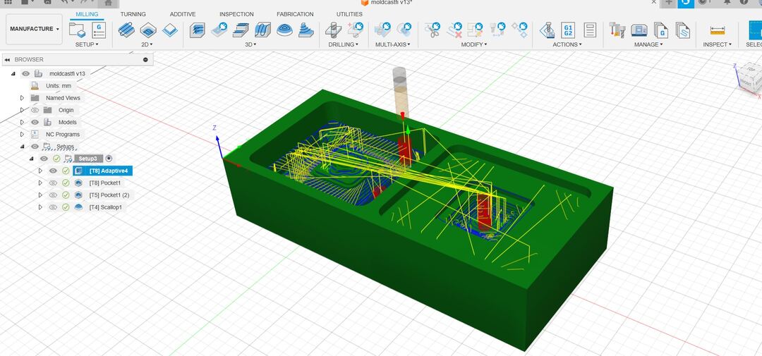
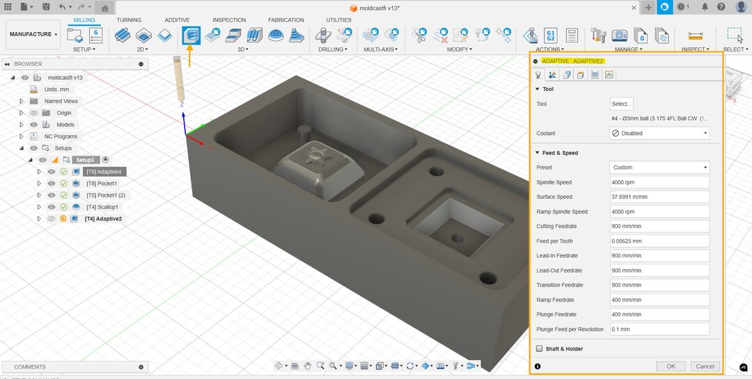
The processes I used for my design were
Adaptive clearing with 6mm flat endmill
Pocket Clearing with 6mm flat endmill
Adaptive clearing with 3mm flatend mill
Scallop with 3mm ball end mill
The values for each process was set according to the milling machine in our lab.
The boundary boxes had to be set according to the process that we were using.
First to remove maximum material we used the 6mm flat endmill in adaptive clearing process .
Then using pocket Clearing with the same tool we take out more areas in between.
The values were entered as shown in the image below.
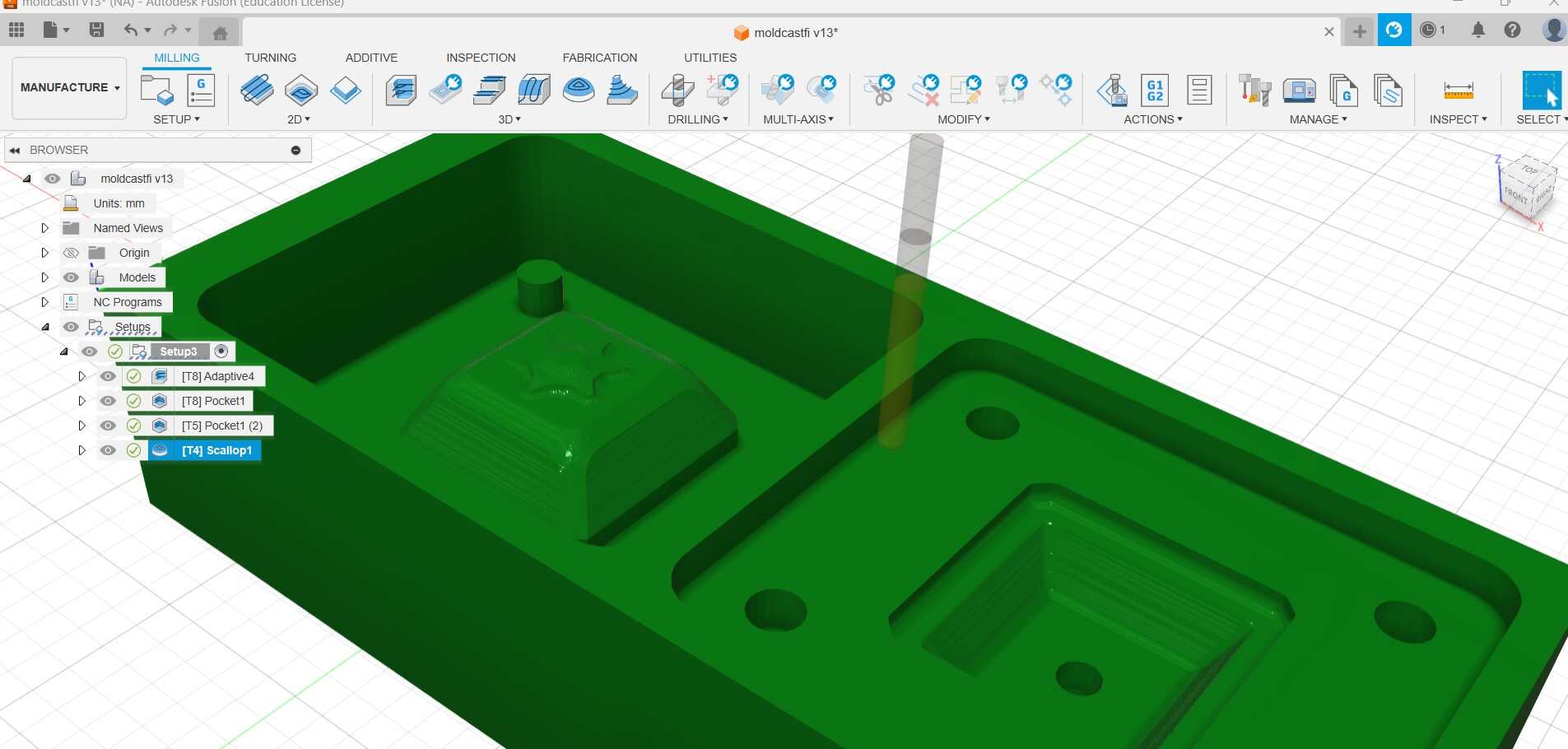
Then to mill out the details we changed the tool to a 3mm flat end mill and cleaned up the rough cuts to make
them finer.
At the end using a ball end mill and the scallop process a clean finish was obtained.
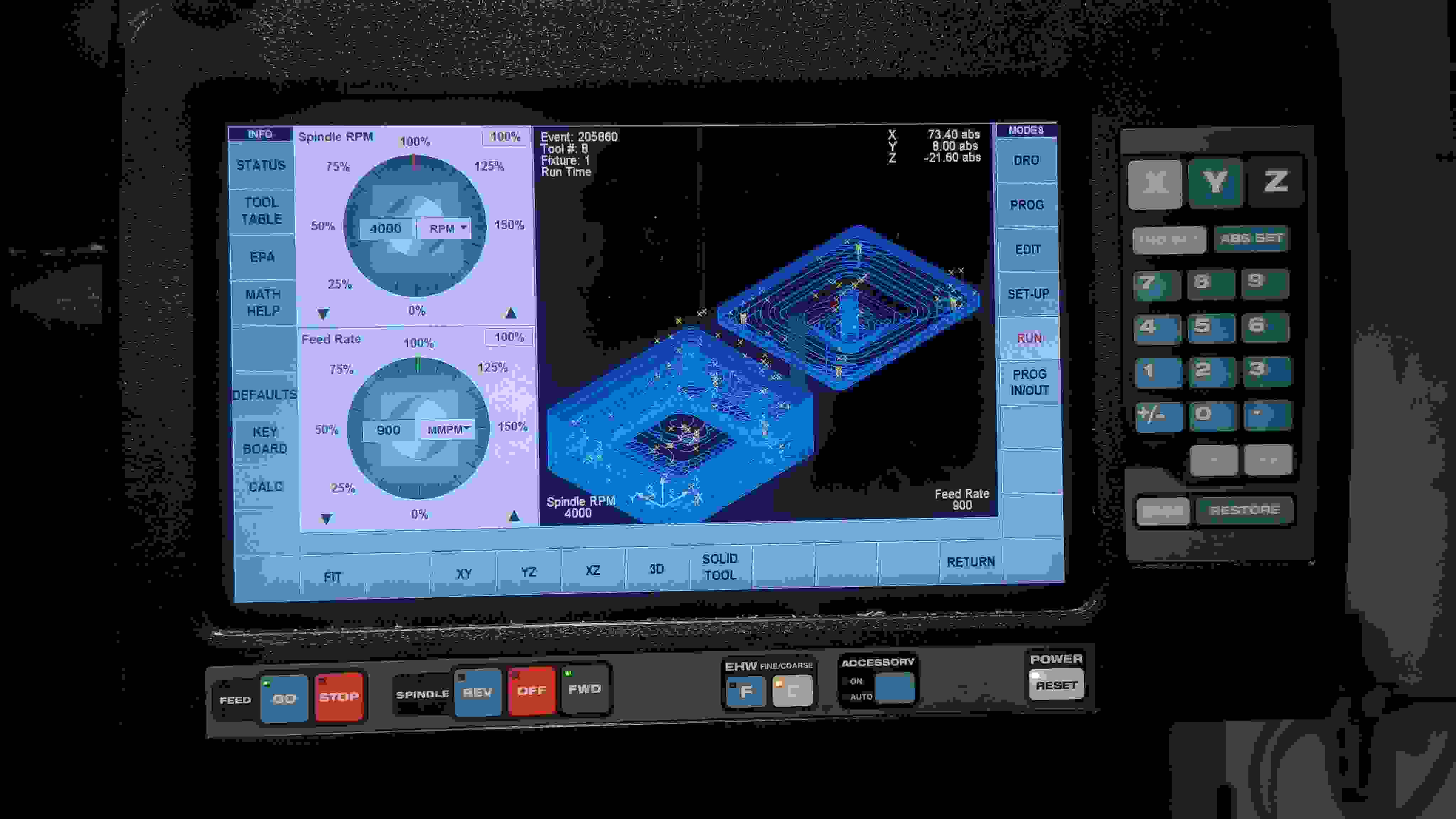
We then can stimulate the toolpaths under the simulate option on the ribbon.
You can see how each process will take place and how the end product will look like.
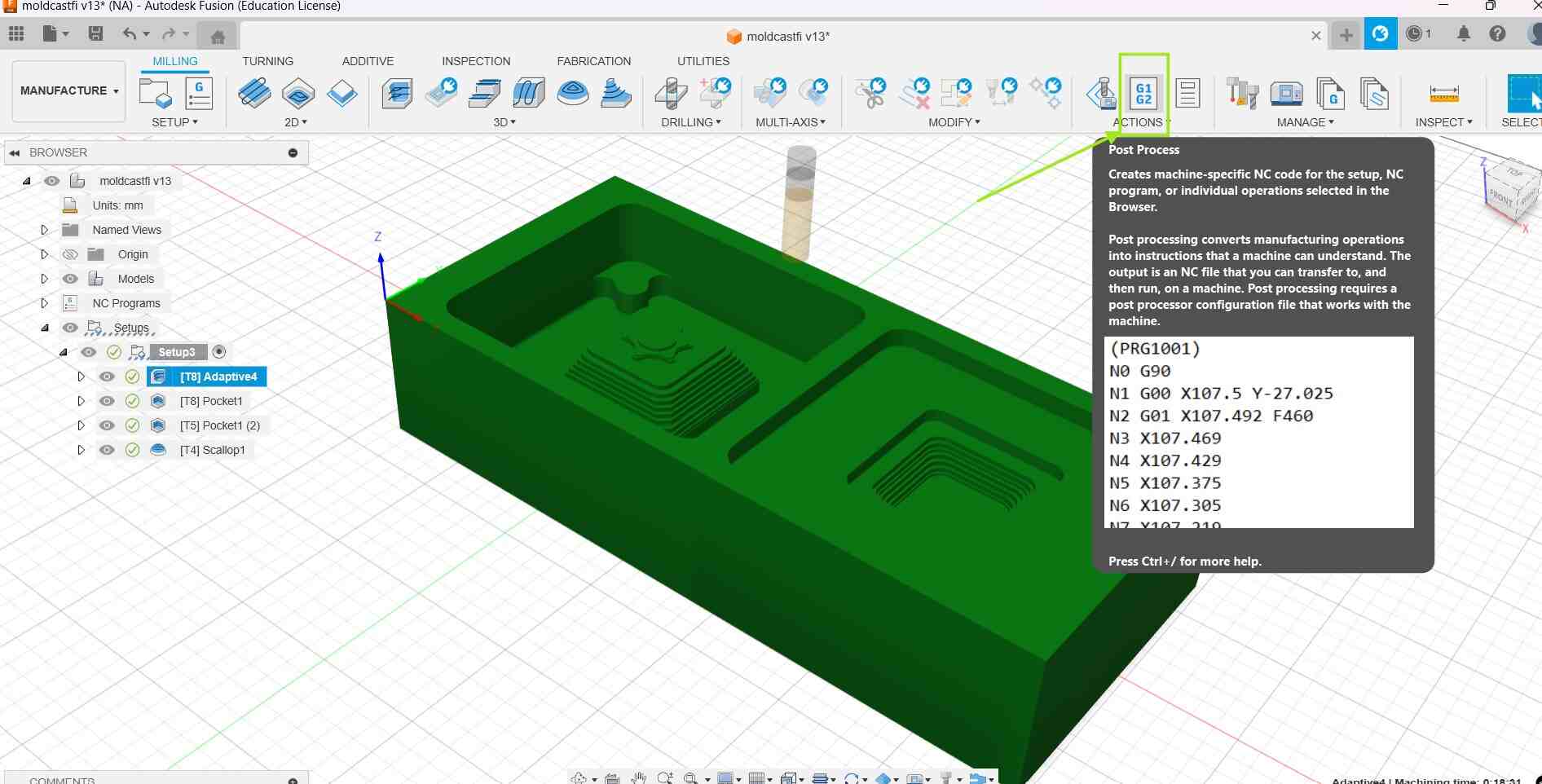
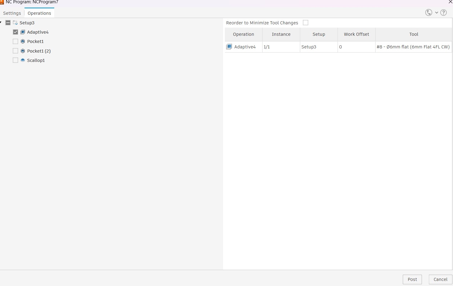
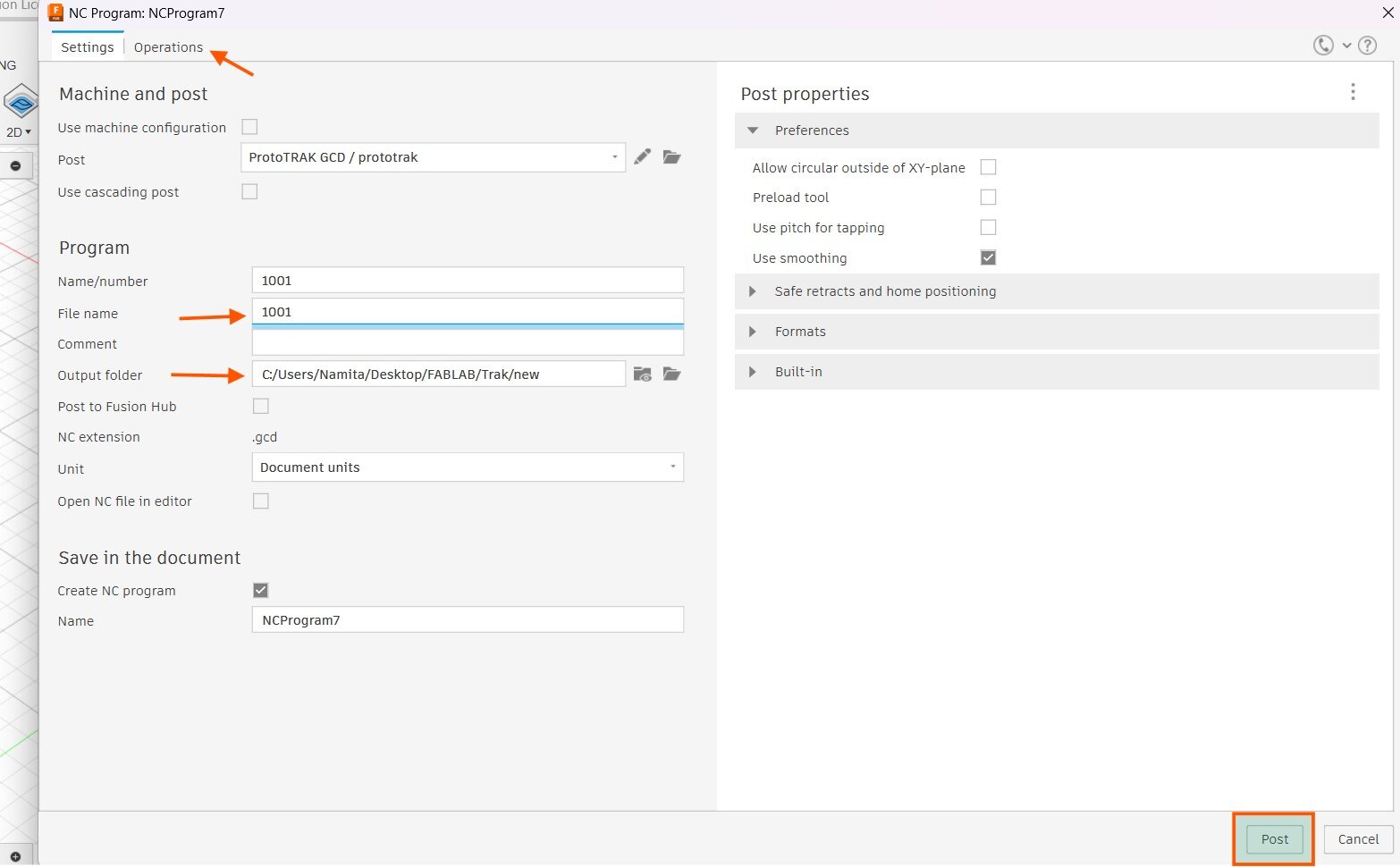
We need to save these process to get the gcodes for the machine. To do so click on the post processes
option and a dialogue box pops up . Then we can select the processes to be saved under options. Set the the
correct
process and then name your file and click on post. Choose the machine that we will be using,which you can find
under the fusion Library.
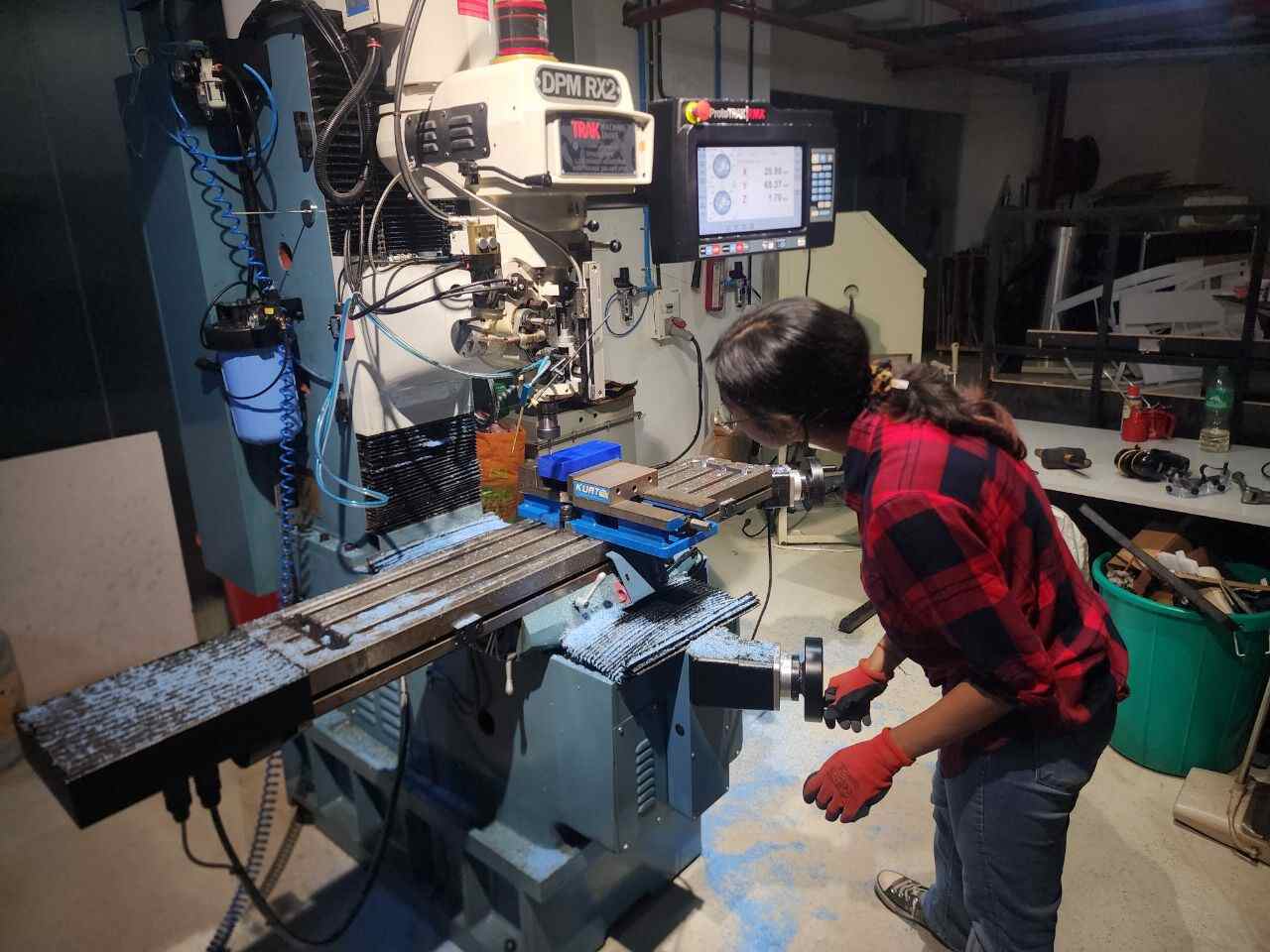
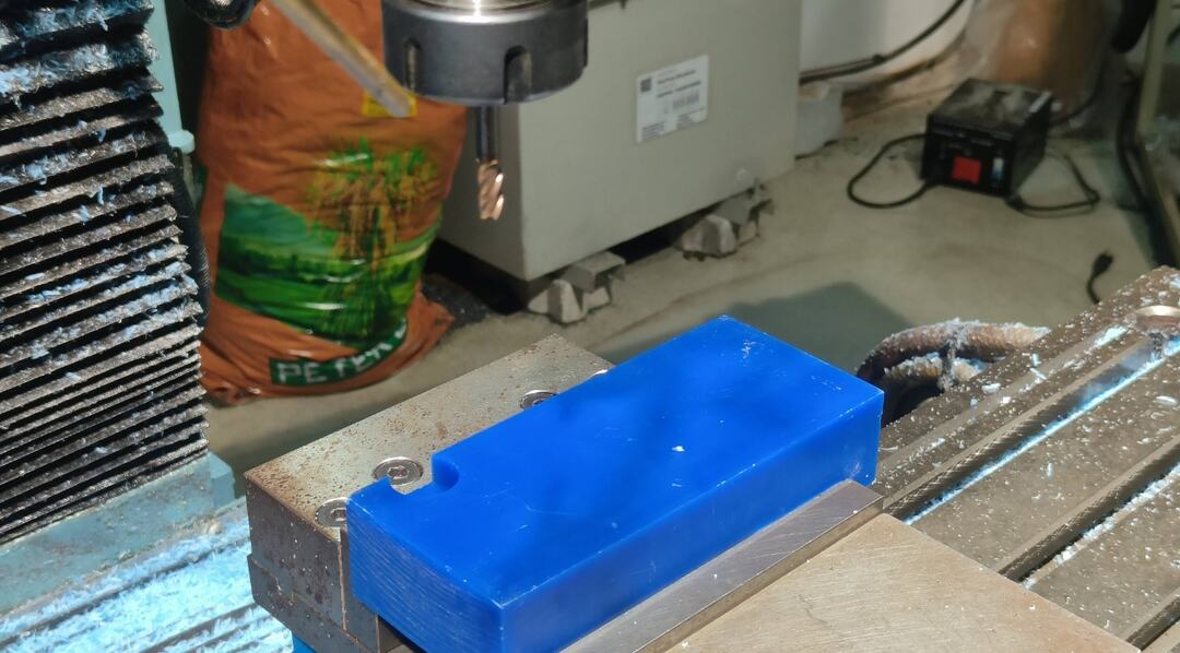
Operating the machine
We used the ProtoTRAK DPM RX2 milling machine to fabricate the positive molds.
We had learned how to operate the machine during the group session.
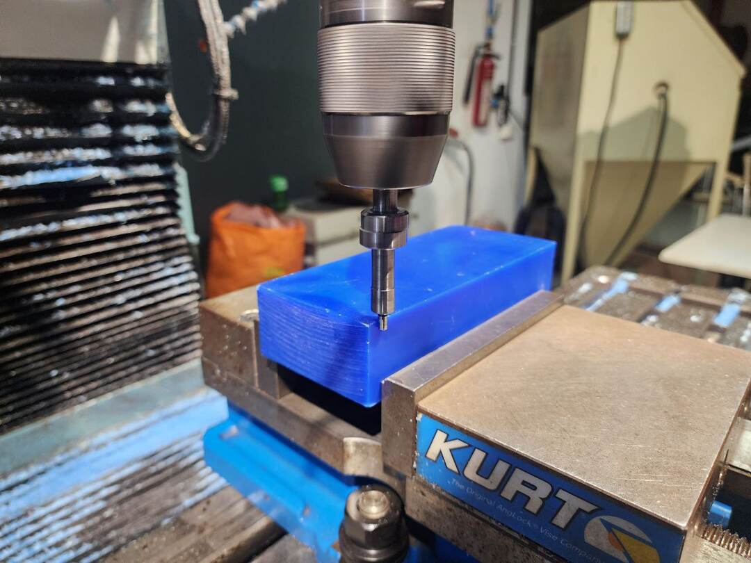
First the workpiece was placed on the the vice and clamped tightly
Next we need to zero the XY and Z axis. We begin by first changing the tool to a edge finder. Make sure the z axis
is kept abve the workpiece.Then by rotating the encoders we move the workpiece near to the toolbit. Press the
spindle forward button to start the spindle.
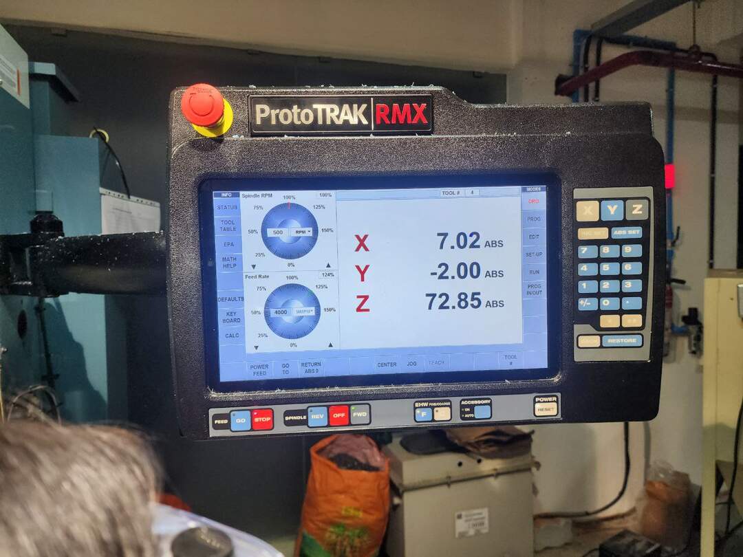
Now navigate the encoders carefully in the Y direction , so that the probe just touches the workpiece(the
eccentric motion of the bit will stop at just as it touches the edge). Then we offset the edge finder just a bit
to set the origin. Type in the Yvalue as -2mm as the origin will be counted from the center of the tool(dia of
edgefinder is 4mm)and click on ABS set . The Yaxis is also set the similar way.
Press Go to move the tool to the origin points.
Next we need to load our program with the Gcodes into the software. Select Prgm IN/Out which will take you to
your files . Select the the file to load. Click Open . the software will ask you whether to overwrite the program
press yes.
Now go to tool table and set the values according to the tool that is being used. The Z offset from the base
requires setting only once, whereas upon tool change, the Z offset must be reset to zero.
To Set the Z OFFSET, we move the tip of the tool to just touch the base from where the initial reading was taken
from the machine.
Next we go into the DRO tab and then move the tool to rest onto p of the workpiece. Here we set the z axis as
Zero and click abs set.
Now we can start the operation. Click on RUN and the START.
The machine will display a message when it is ready to process the operations.
First we click on TRAKING to manually encode the machine and bring the tool to start the milling operation. This
is done so as to check if all the values are set correctly and the machine is following the toolpath correctly.
Initially i made an error even after checking the tool path. This was because the width of the workpiece was
smaller than the CAD model. MAke sure to check dimensions properly . Thankfully the piece could be salvaged as it
was not a critical component to the model.
The origin setting and the rest of the processes had to be repeated again.
Once that is ensured we can start the automation of the machine by first pressing STOP and then click on CNC
RUN. To view the tool path select on “SHOW PATH” from the screen.
This was a 6mm flat mill Adaptive clearing operation
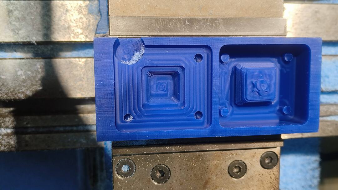
Once the operation with the 6mm bit was done the Z will retract and the machine stops. Now we need to change the
tool bit to a 3mm flat end mill to start the finishing processes. We just need to set the Z offset again in the
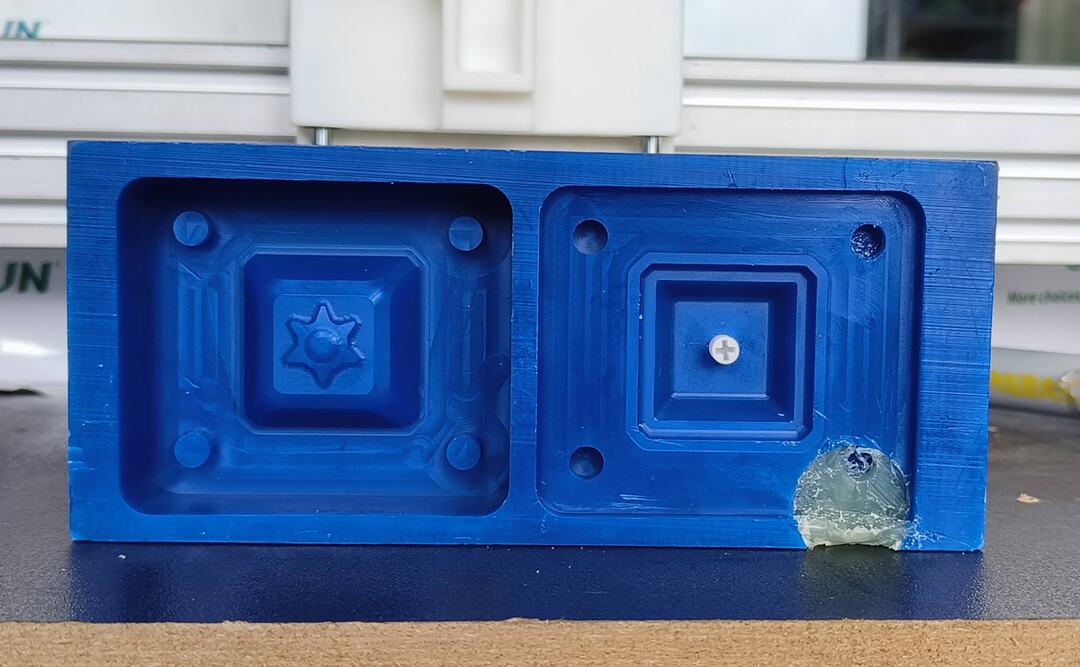
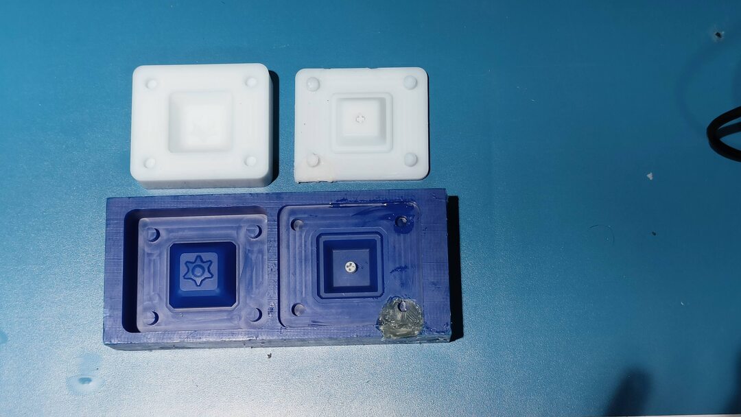
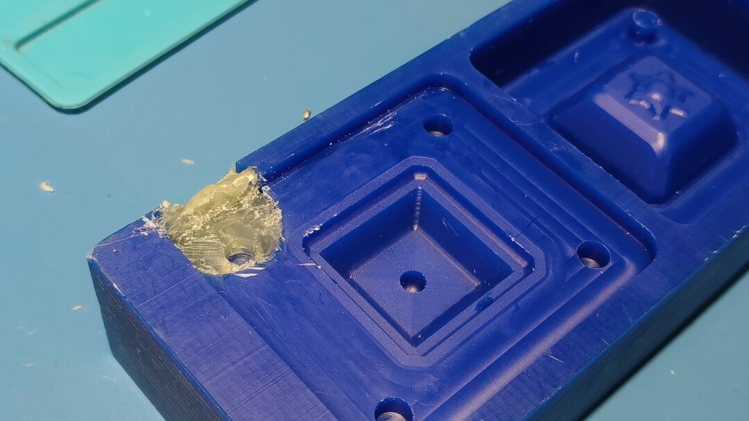
This was how the mold looked after the milling process.
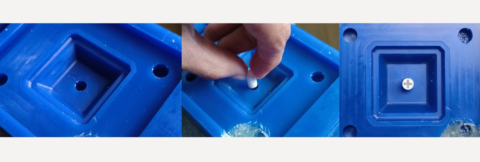
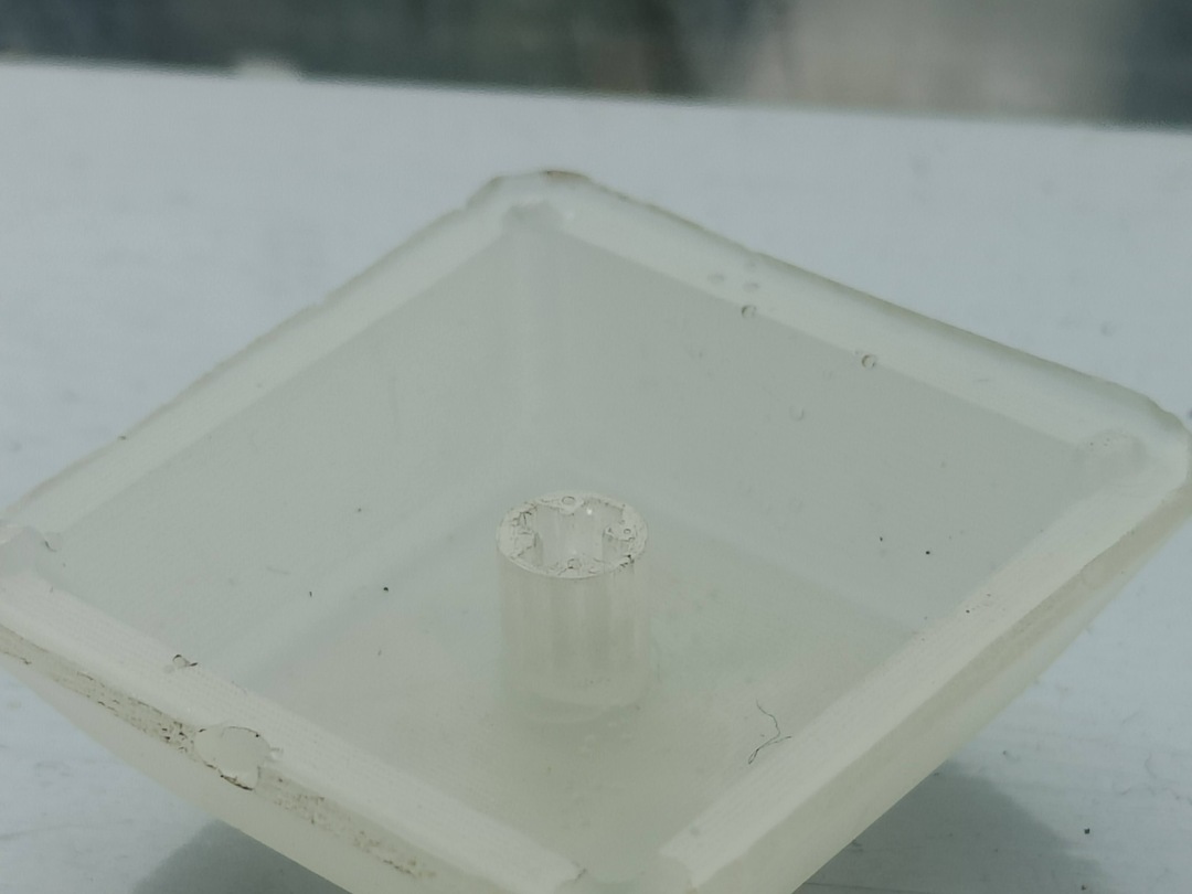
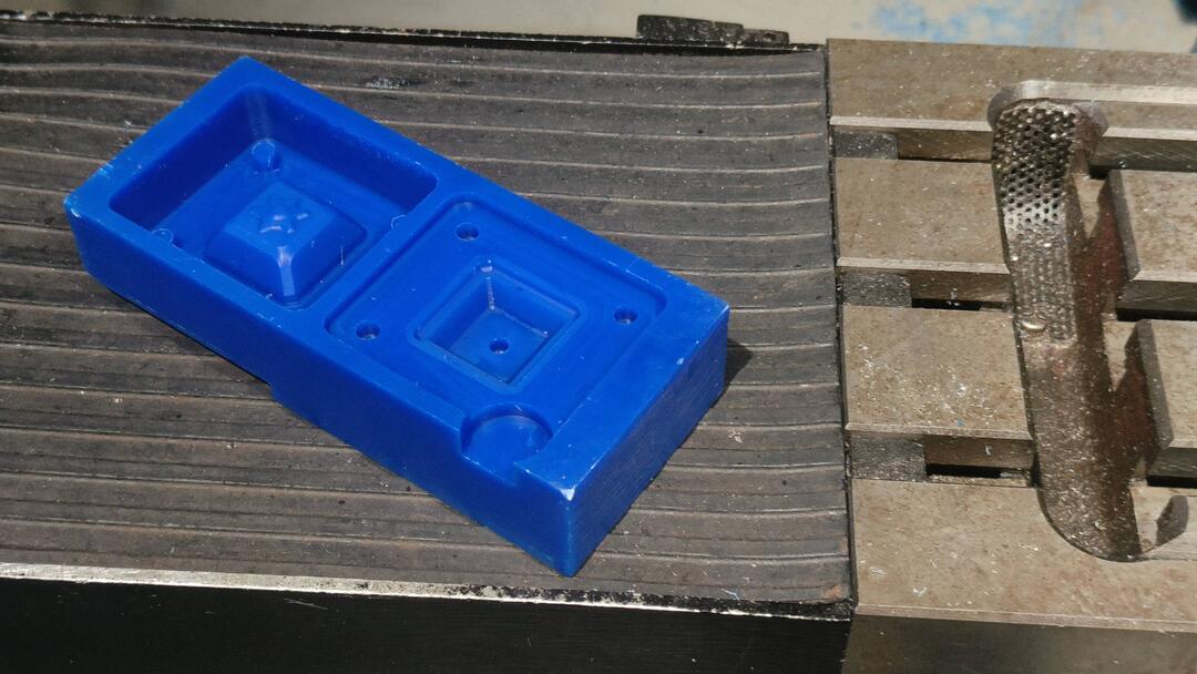
I had to take care of the hole that was accidentally millled initially and also try to make some space for the
registration pin. I made use of hot glue gun to seal off the bounding edge so that there wont be spillage.
The shaft was also placed on the mold . Now the positive mold is ready .
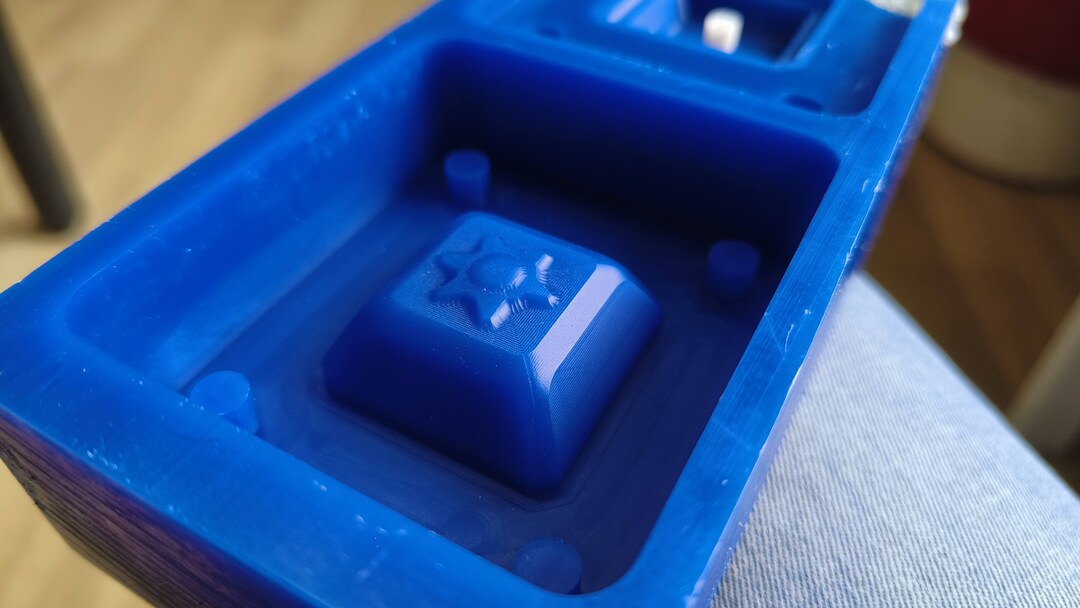
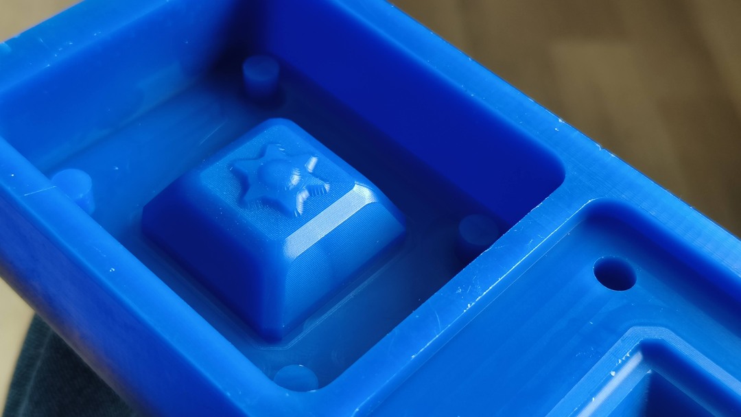
The final wax mold looked like this
Molding with Silicon
Once the the mold was ready , i could move on to preparing the silicon to mold.
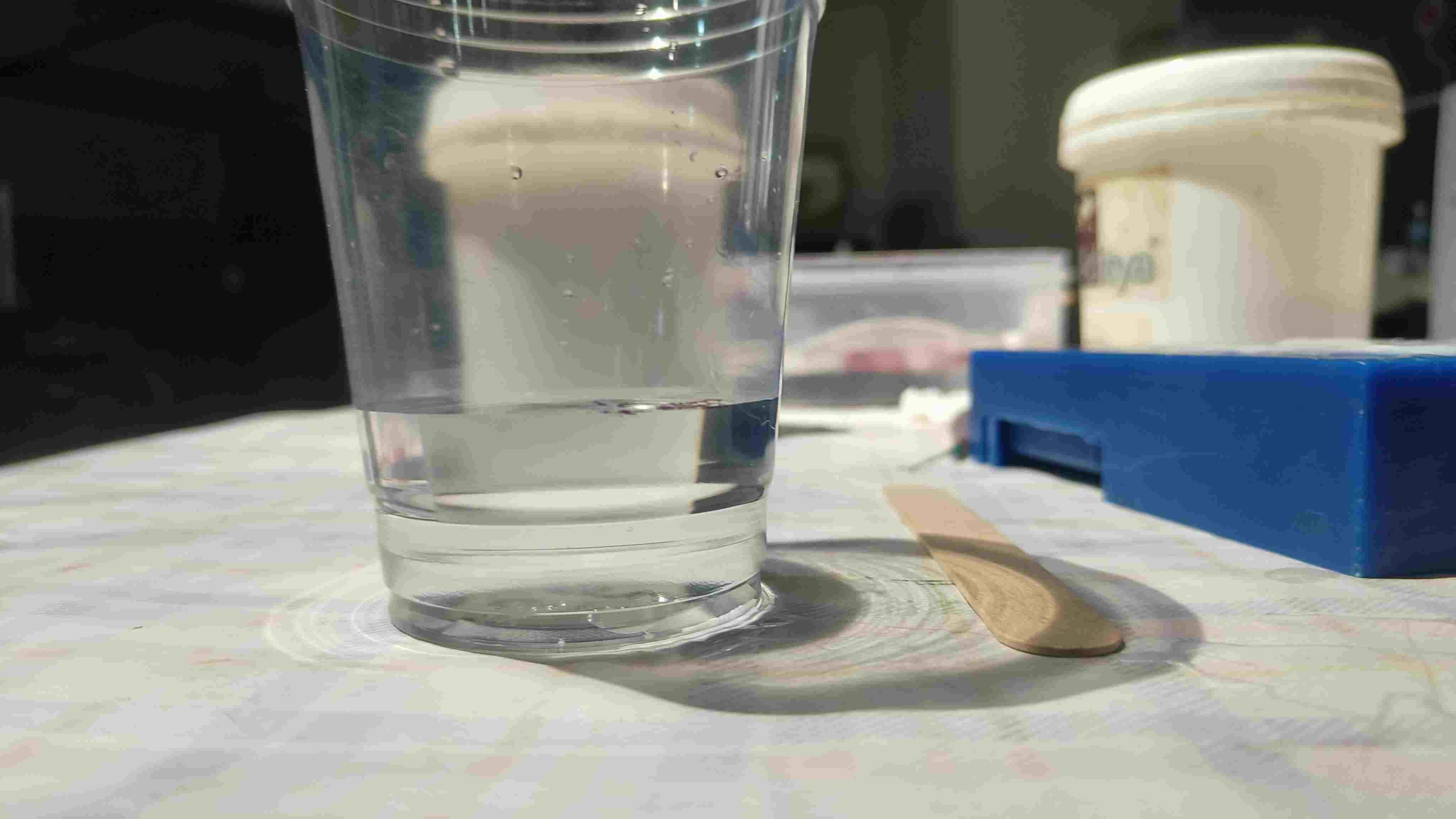
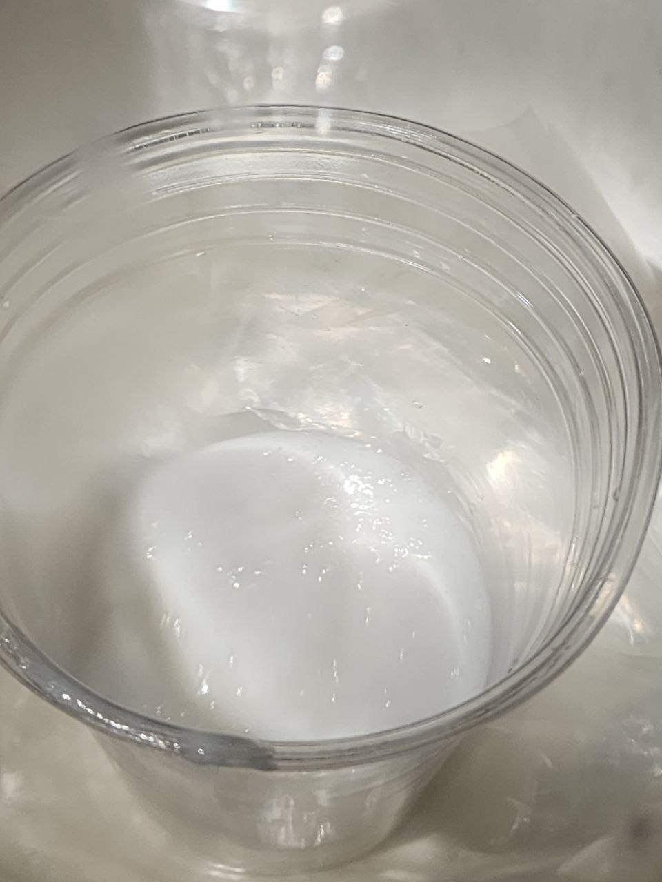
First we need to find the volume of the mold. To find that we fill the mold with water upto the brim and then pour
it into a cup. Then mark the the water level in the cup.
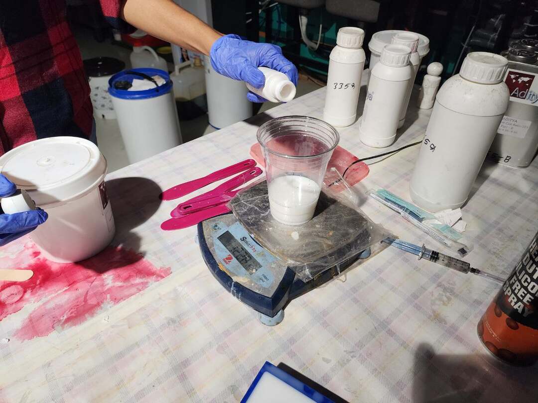
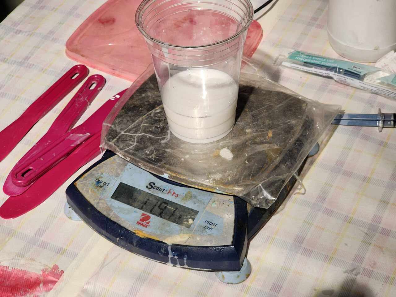
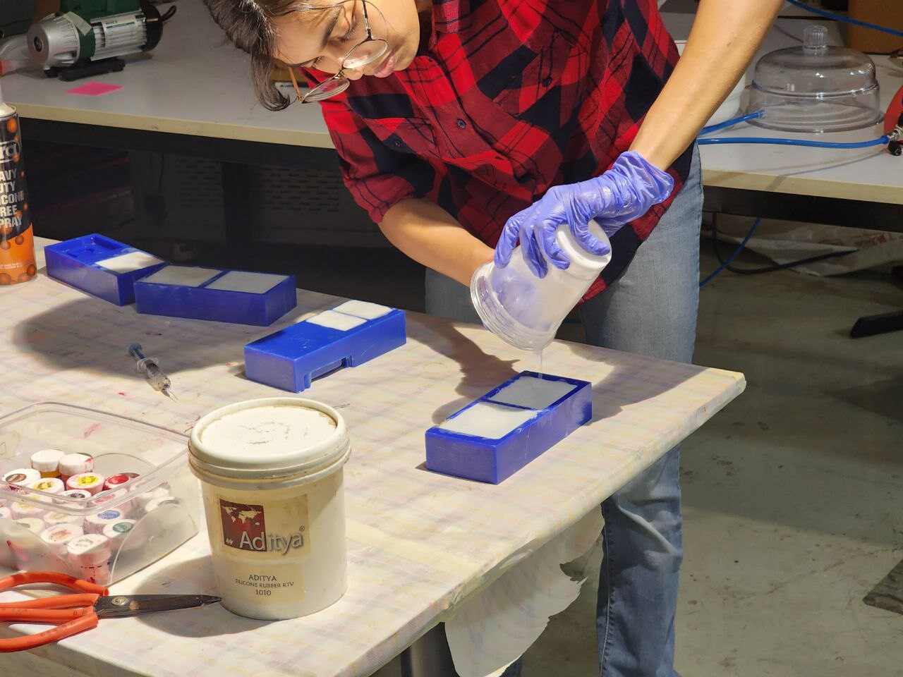
Now empty the glass and keep it on a weighing scale and set the value of the empty cup as zero. Now we pour the
the silicon and the curing agent in the ratio as mentioned by the manufacturer.
In our lab we have the “Aditya Silicone Rubber 1010” and “Aditya Curing Agent”. The ratio was 1kg of silicon :25-30gms
curing agent
Mix it up well and the place it inside a vaccum chamber to suck out the airbubbles
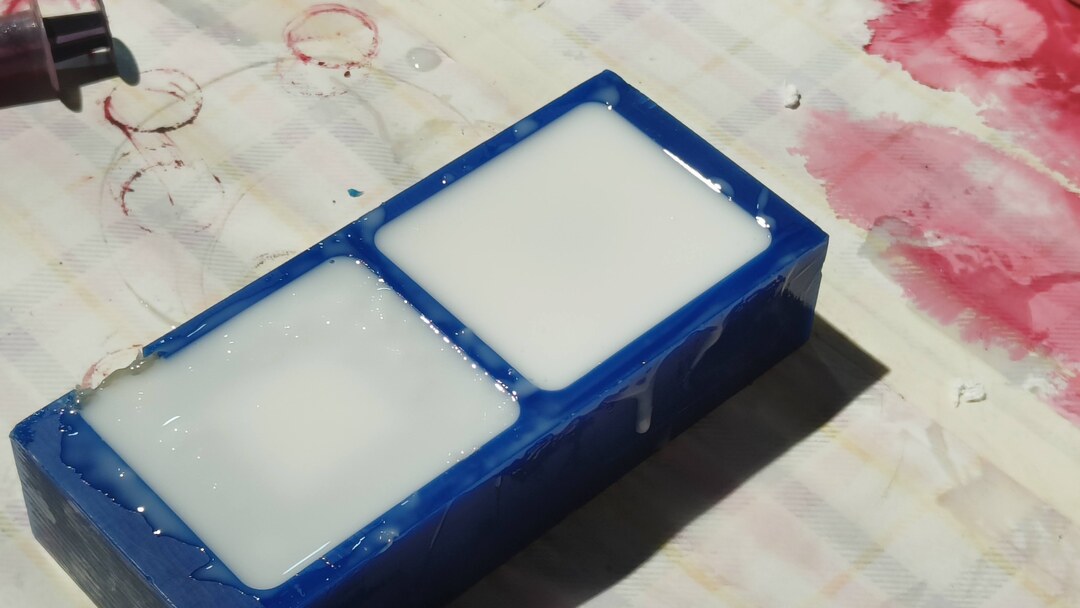
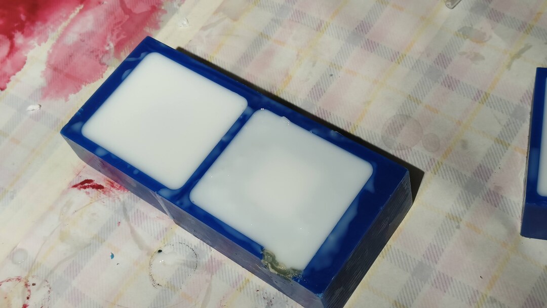
Once that is done, Pour the silicon into the molds and fill it up. Make sure all parts are covered well. Pat
down the mold to release air bubbles and then leave it to rest for 24hrs.
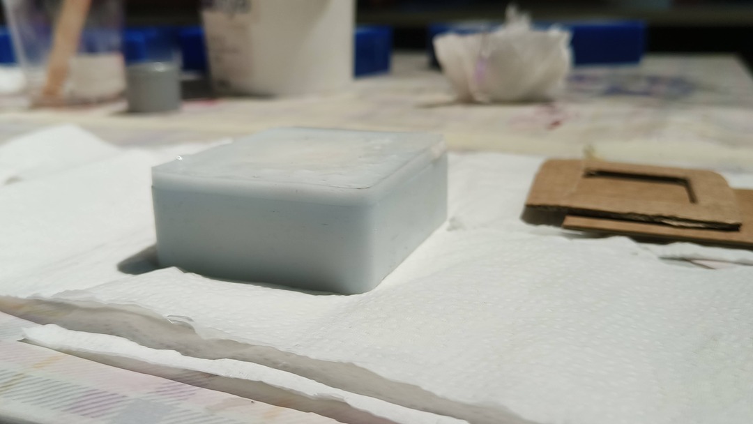
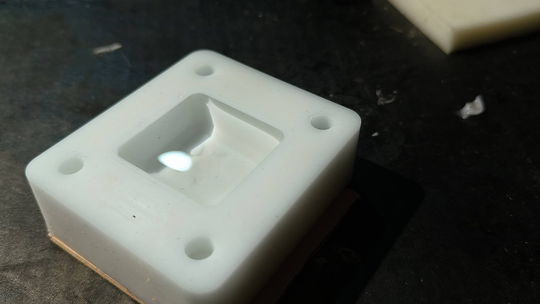
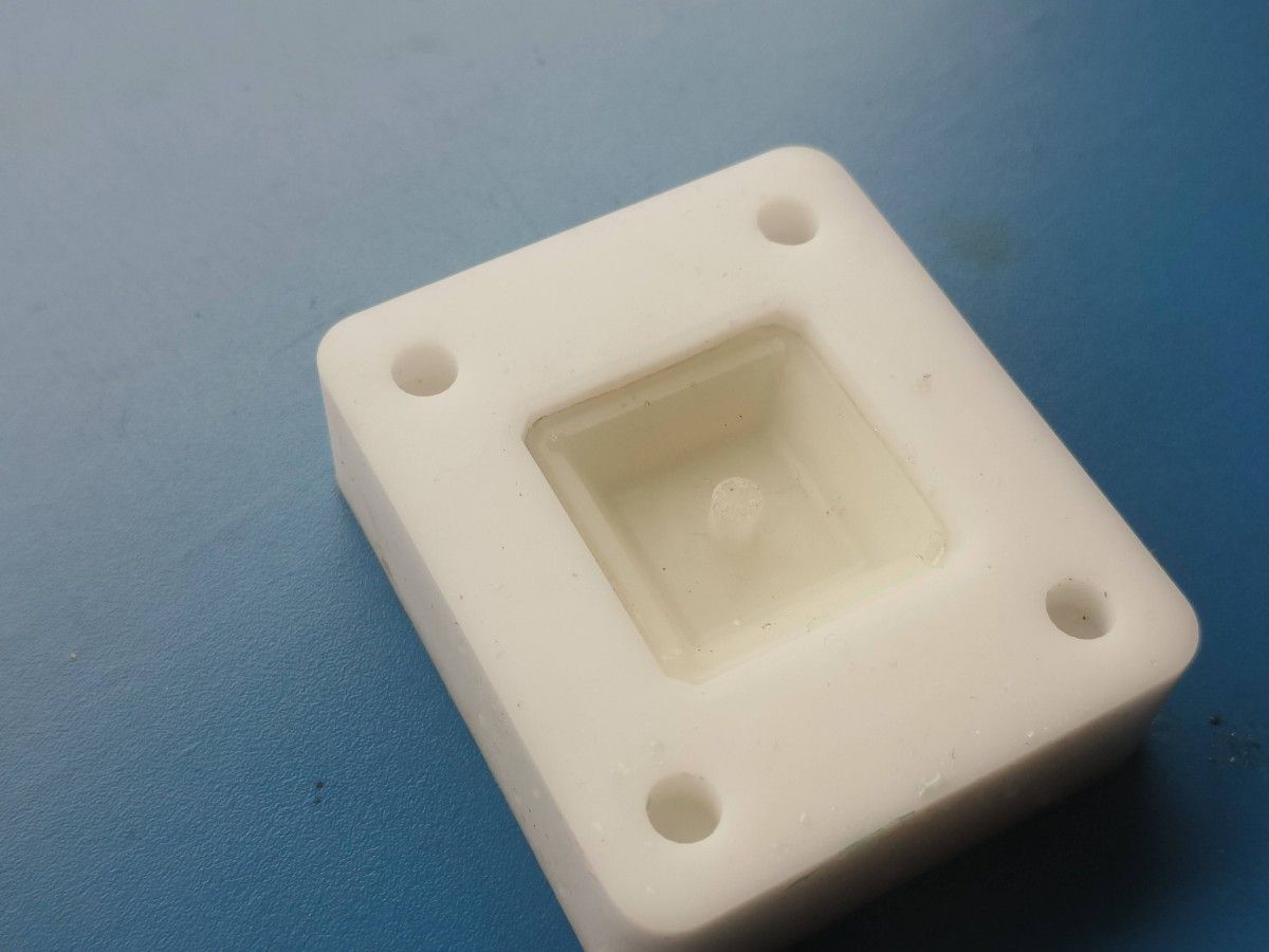
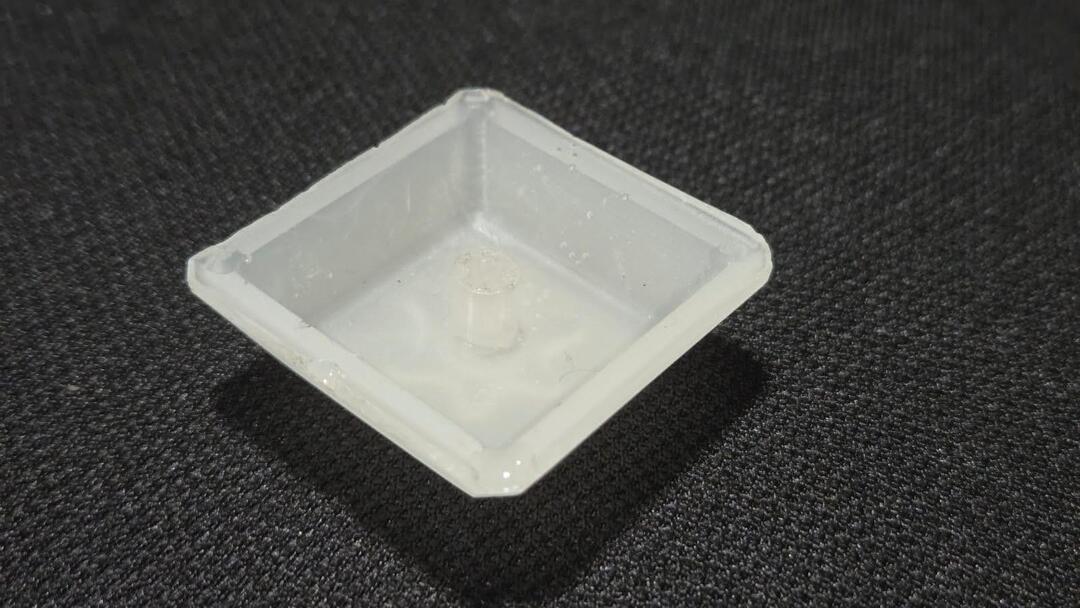
The next day after checking whether the silicon was set completely i peeled out the silicon mold from the wax. I
was happy with how it turned out as it came out quite clean.Even the shaft part turned out perfectly.
I was kind of worried if the hot glued part would stick to the silicon , but that came out better than expected
too.
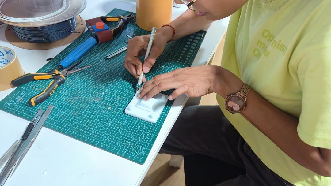
There were some portions that had to be cleaned up .
So i cut off the excess pieces around the registration pin that was came out of the hot glue part.
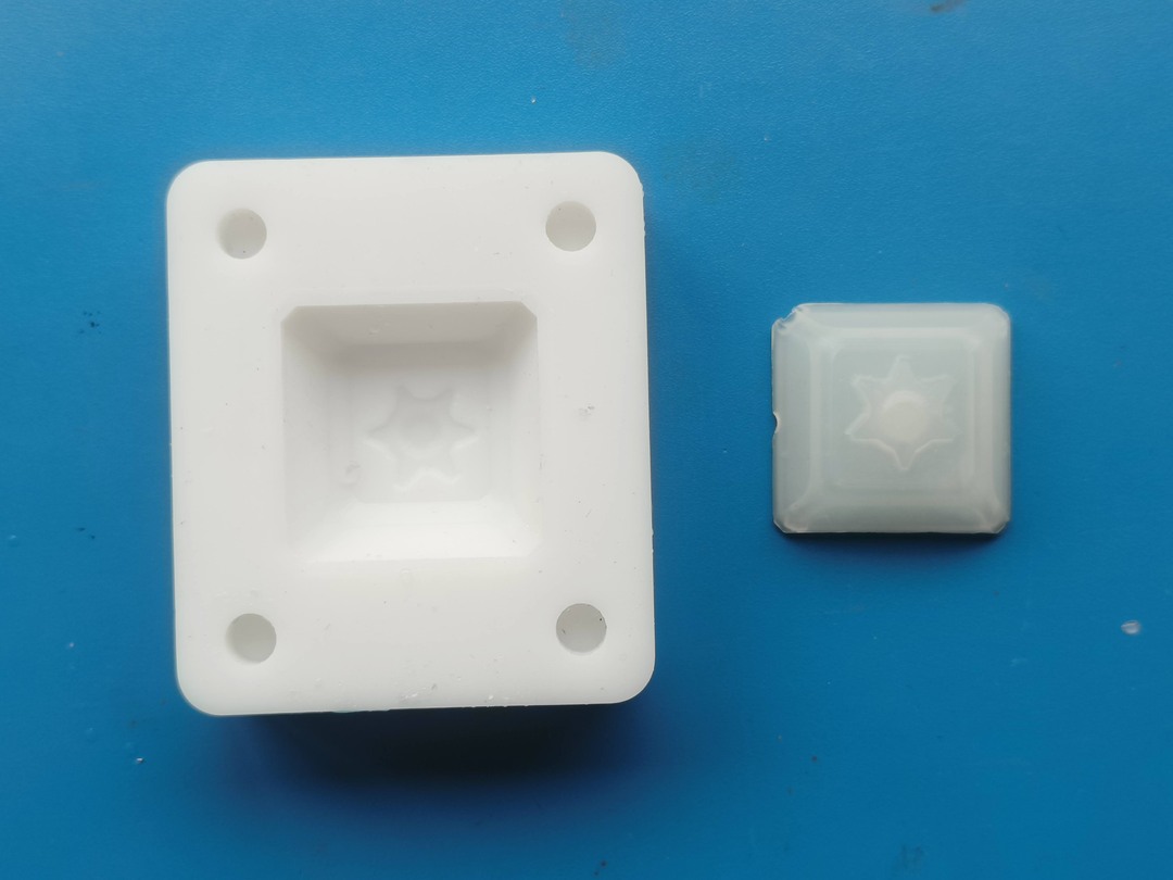
The molds sit perfectly when closed.
Resin Casting
The resin that we had to use was "Aditya Ultra Clear Cast Epoxy" which is a clear resin . We can add a few drops of dye to colour it according to ur need..
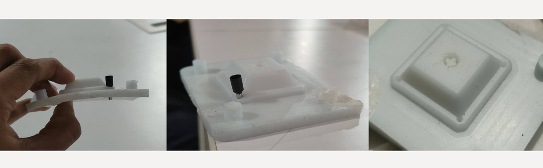
I had to punch holes into the mold to allow the nose of the syringe to be inserted for the resin to flow
through.
You can do this using a small metal pipe with a sharp edge to punch through the silicon. I used a wire ferrule
which was available in the lab.
4 holes were punched to each corner of the the step on the mold.
To test if the holes were properly punched and to make sure the resin will flow through , the syringe was
filled with water and lodged into the holes made on the mold and injected.
The water came out through the other holes thereby confirming that everything was properly distributed.
Before I close the mold, the volume of resin that would be needed to fill the mold needs to be calculated.
I filled water into the mold and poured into a glass and marked the water level. The volume will be a little more
than required as
the second part of the mold will take up space
in the first mold leaving space only for the shell part.
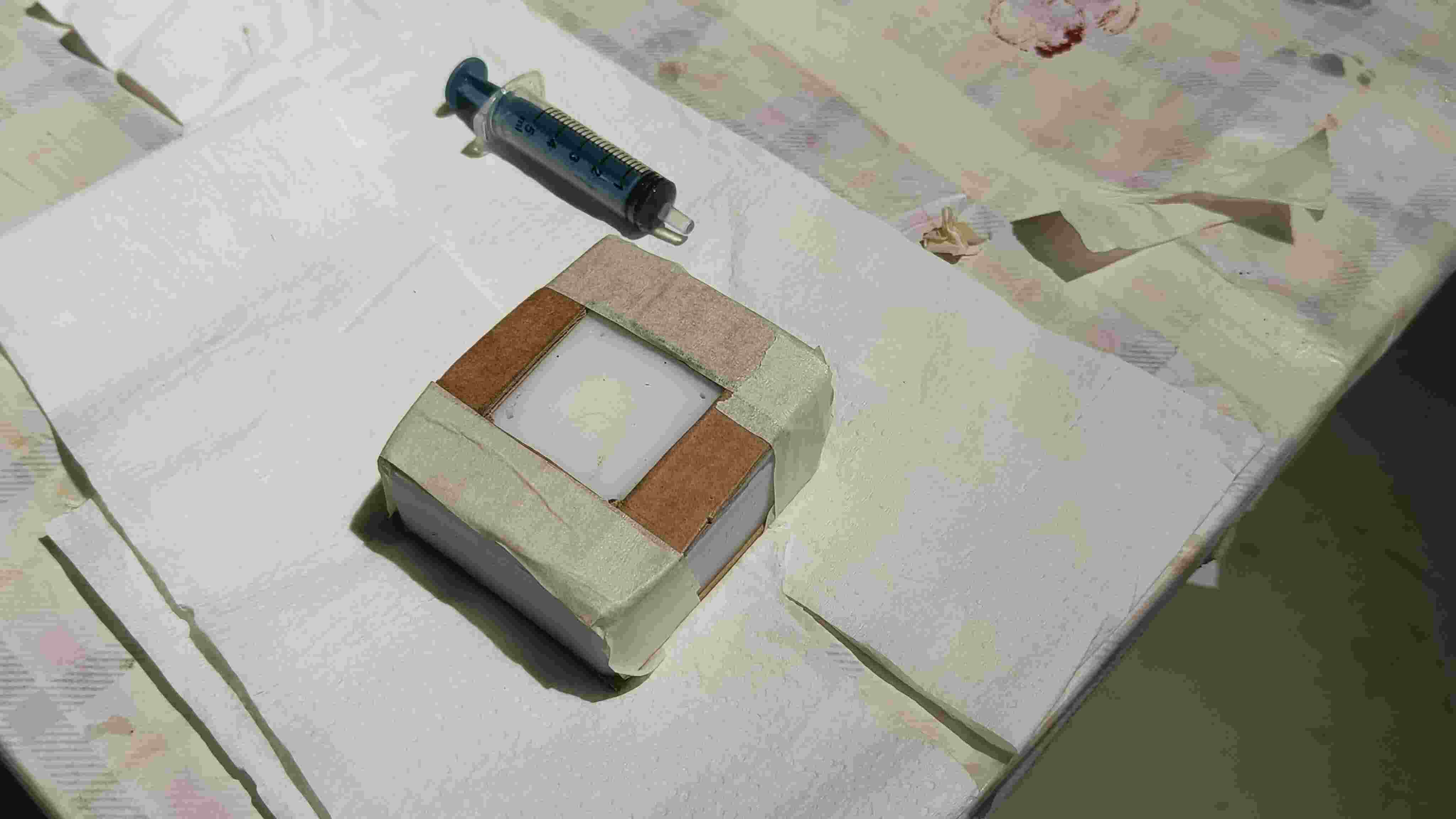
Now we can close the mold. We should make sure that the two parts are properly sealed and wont come off when the
resin is poured into it. Two pieces of cardboard was place on the top and bottom of the closed molds and then
taped up securely .
The cardboard placed on top had a slot cut out that accommodates the holes punched as they need to be injected
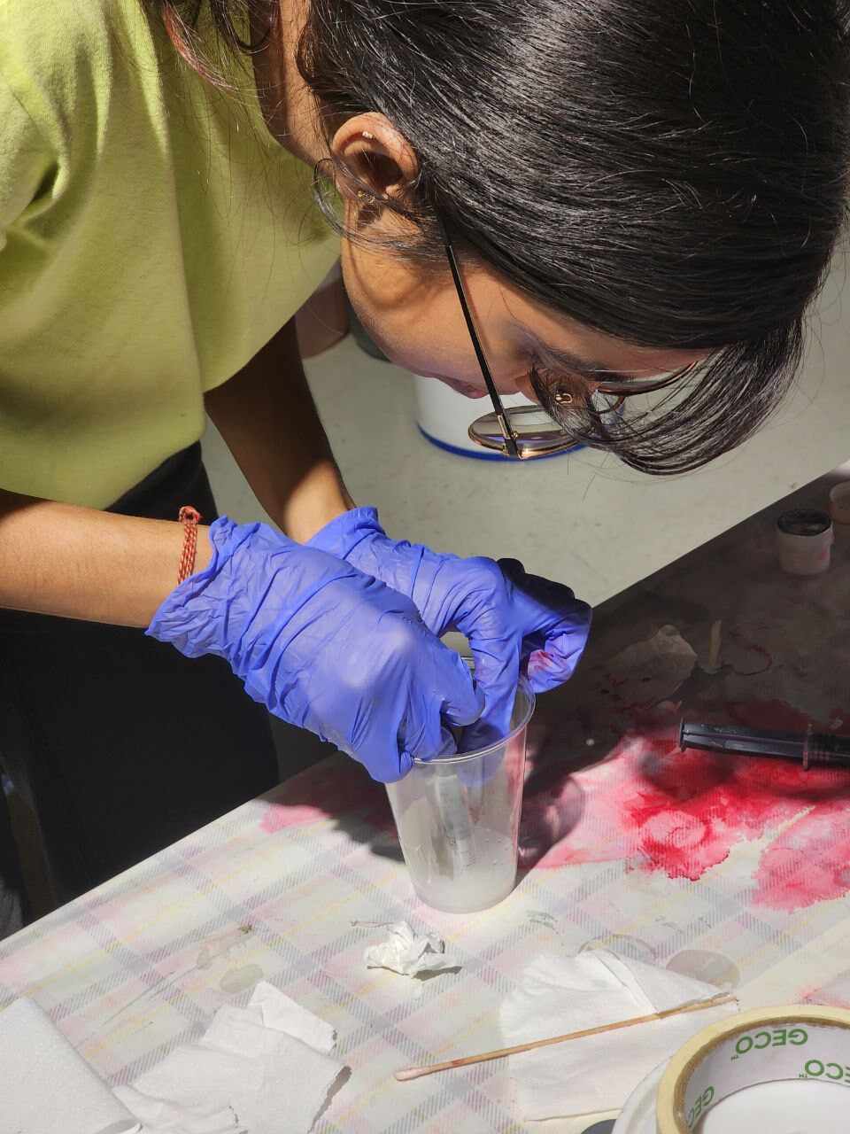
Once the mold is ready, we can move on to prepare the resin. We are using the 'Aditya epoxy resin - 37 Part A
and Part B'. The ratio in which the compounds to be added is 2 Part A : 1 Part B by weight.
The glass on which we had previously marked the water level for the volume of the mold was emptied and placed on
to a weighing scale and set to zero.
Then Part A was poured almost 2/3rds of the line and the weight was noted . The Part B component weight
calculated using the ratio calculator and then that amount was poured into the cup.
I added a 1-2 drops of White dye into the cap as i wanted the keycap to be translucent ,just enough for the
light from the switch to be diffused.
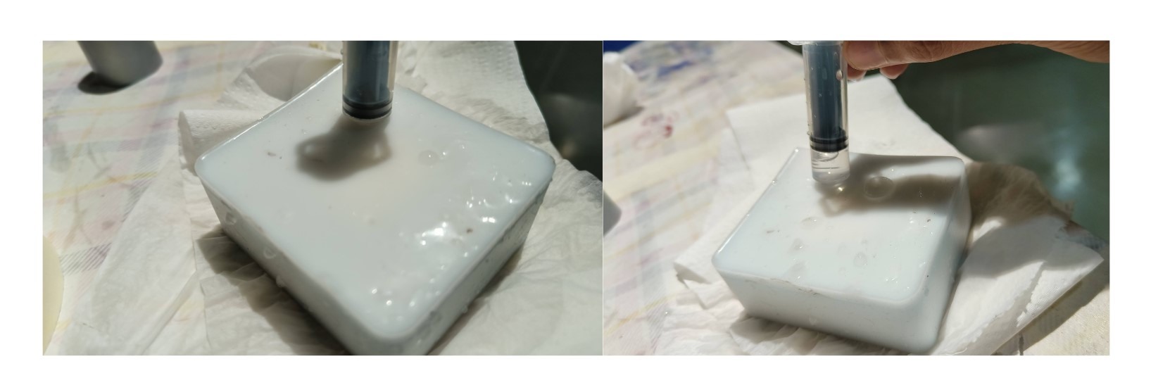
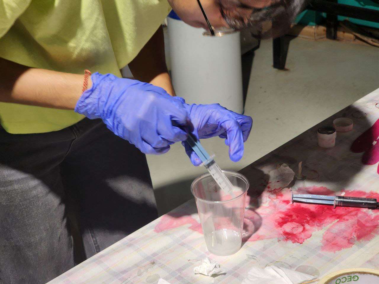
Then I filled the syringe with the resin and inserted it into the holes on the silicon mold. The resin was
slowly injected into the mold until it came out of the other holes.
Then the mold was left to set overnight .
Once the resin was completely dried i opened the mold.
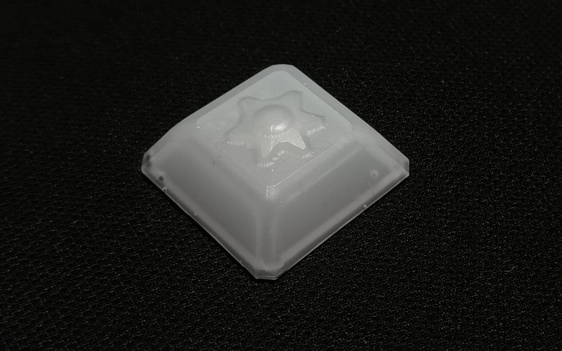
Hero Shots
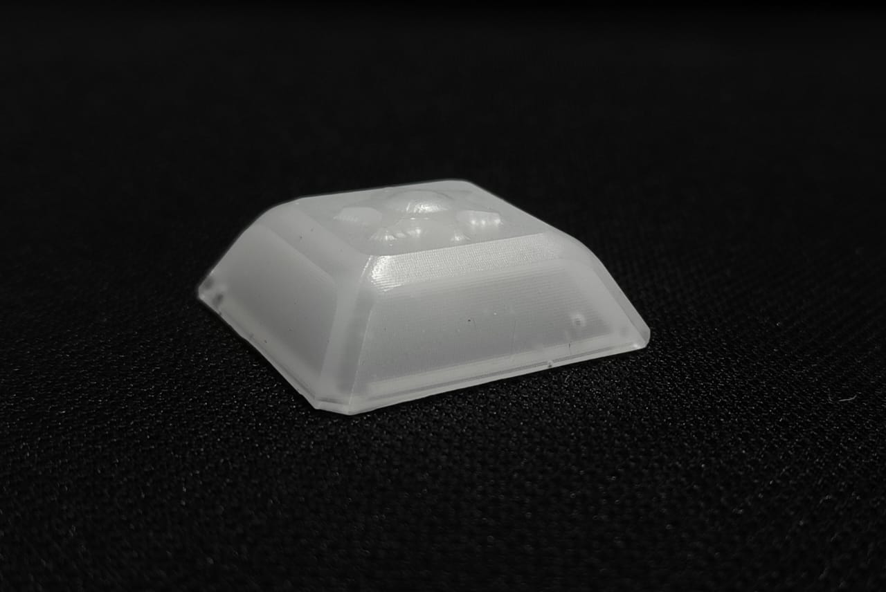
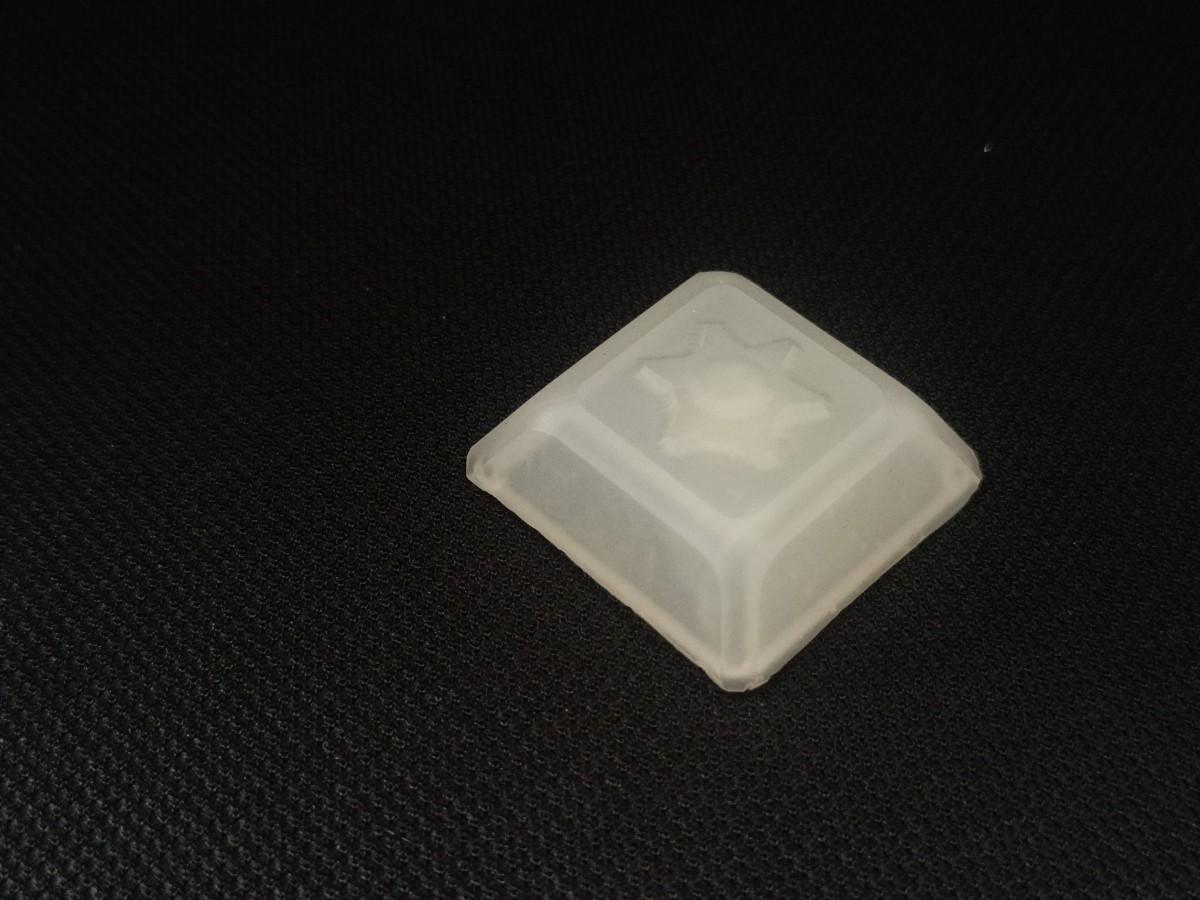
The Keycaps came out easily from the silicon mold. The finish was smooth and of good quality.
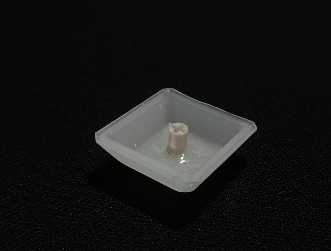
I tried to cast the resin again to get the keycap and the stem in one piece. I followed the same process. The only change was that i poured some resin first into the stem mold and made sure it went all the way down covering the entire part.
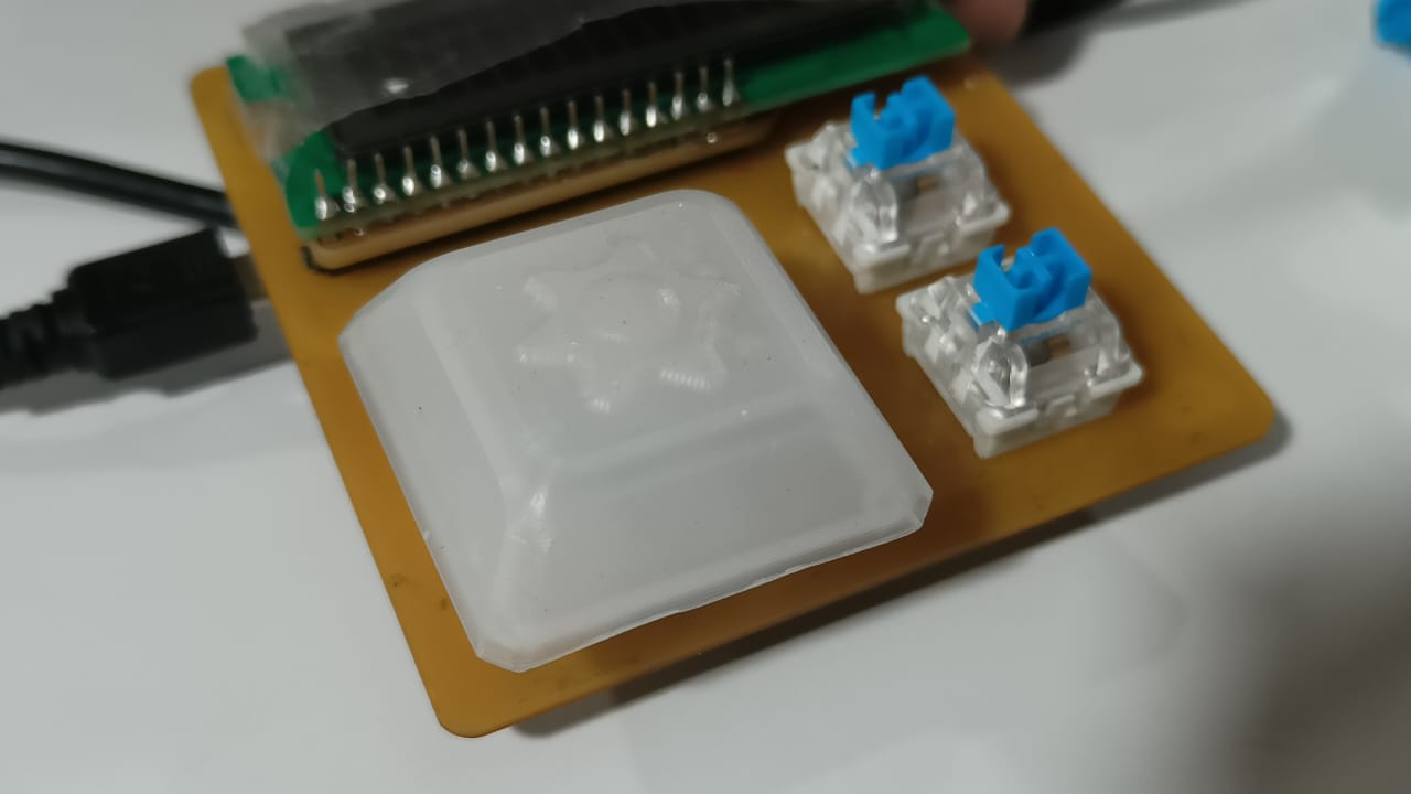
This time the keycap came out perfectly with the stem in one part!! I attached the keycap to a board i had previously made to check out how the light gets diffused through the keycap.
 At its core, mold making involves the creation of a negative space or cavity that perfectly mirrors the desired
object's shape. This cavity then serves as a template to produce multiple copies of the object, whether it be in
plastic, metal, or any other material.
At its core, mold making involves the creation of a negative space or cavity that perfectly mirrors the desired
object's shape. This cavity then serves as a template to produce multiple copies of the object, whether it be in
plastic, metal, or any other material.
 The values were entered as shown in the image below.
 I had to take care of the hole that was accidentally millled initially and also try to make some space for the
registration pin. I made use of hot glue gun to seal off the bounding edge so that there wont be spillage.
I had to take care of the hole that was accidentally millled initially and also try to make some space for the
registration pin. I made use of hot glue gun to seal off the bounding edge so that there wont be spillage.
 The shaft was also placed on the mold . Now the positive mold is ready .