Application and implication
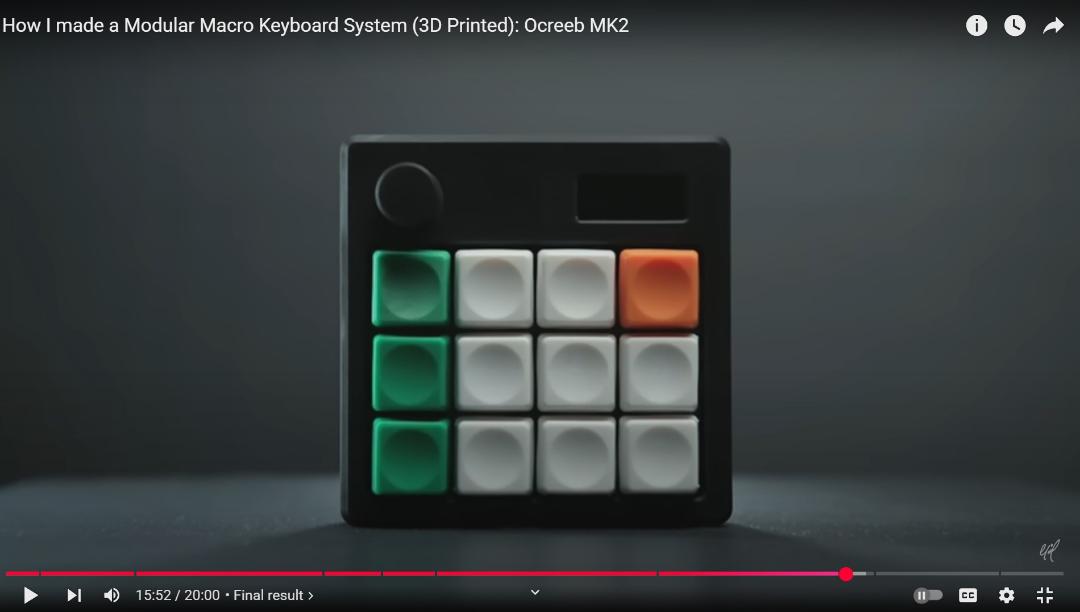
This is where I showcase my final project .
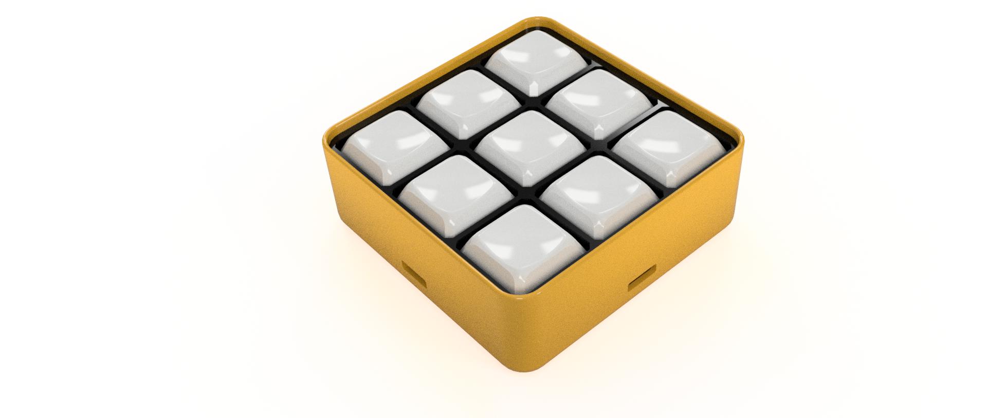
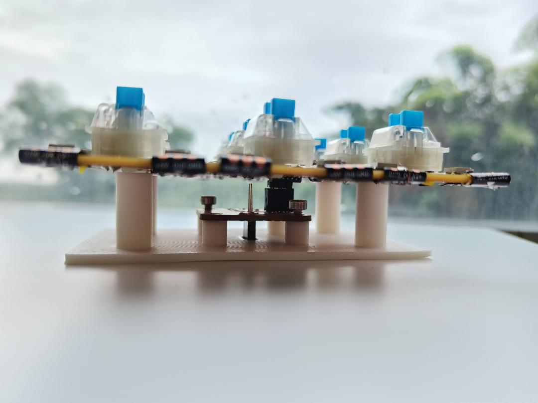
*Final product shoot at the end of the page!
For my final project i wanted to explore how 8bit games can be brought back into this era. I also wanted to explore the aspect of being in the present and how it can help enhance cognitive function through strategic thinking and problem-solving, increased social interaction and bonding, and opportunities for relaxation and stress reduction. In this age where gaming has become individualistic, i would like to cultivate a sense of shared experience back into game spaces.
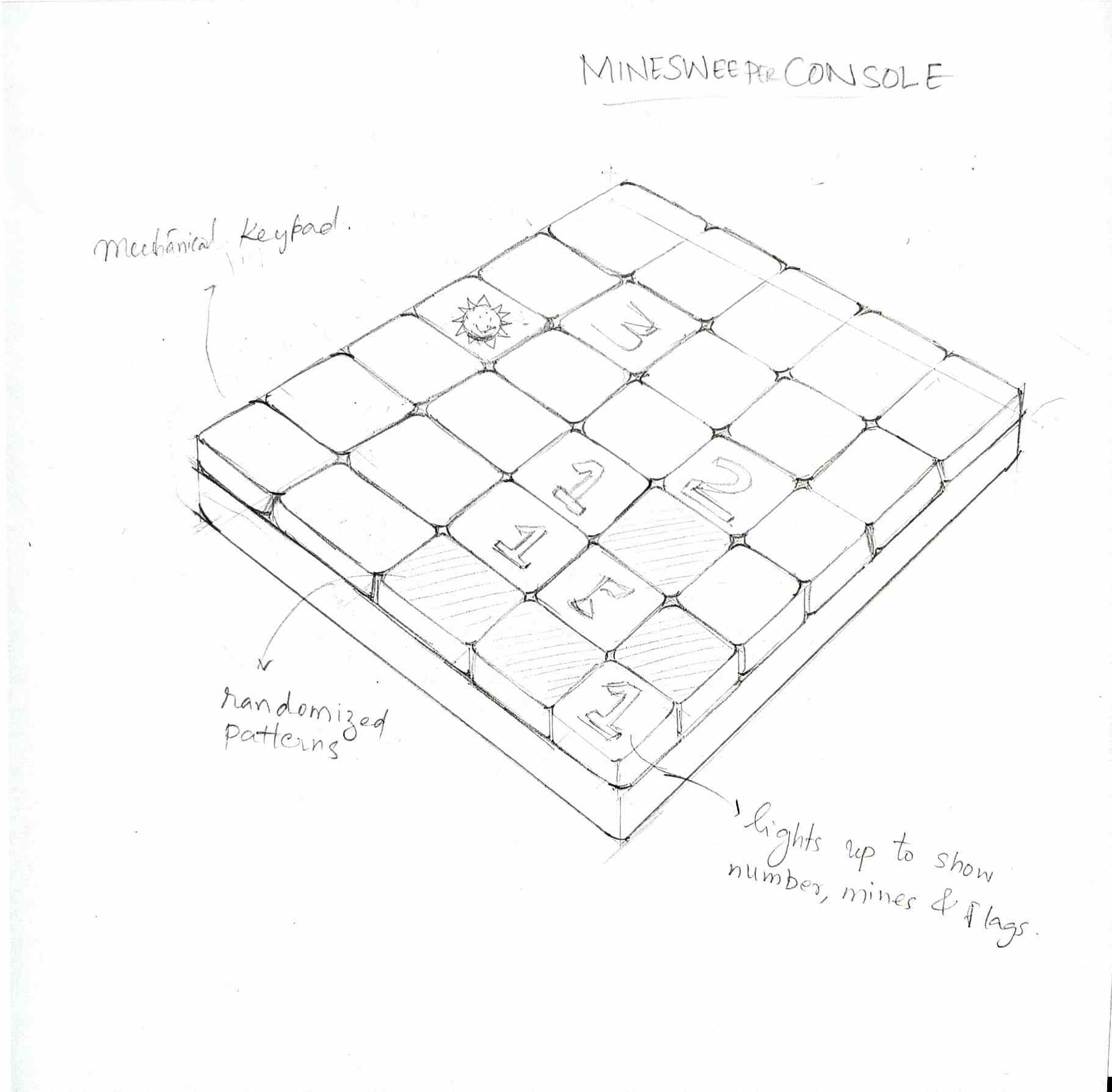
We all have played Minesweeper as children on our computers. Following the earlier said concept of nostalgia for the future, i wondered how it would be to bring the game into the physical world while keeping the soul of the game intact. There would be randomized set of possibilities to play for each person and similar effects of game such as the sound of the original game can be added to the physical playing console.

We all have played Minesweeper as children on our computers. Following the earlier said concept of nostalgia for
the future, i wondered how it would be to bring the game into the physical world while keeping the soul of the
game intact. There would be randomized set of possibilities to play for each person and similar effects of game
such as the sound of the original game can be added to the physical playing console.
Minesweeper is a puzzle video game where the objective is to uncover all safe squares on a grid without detonating
any mines (bombs). The game board is divided into cells, some of which contain mines and others that are safe.
Players uncover cells by clicking on them, revealing either a number (indicating the number of adjacent mines) or
a blank tile (if no mines are adjacent).
This was the origin point of my final project journey.
The assignment for the first week was to brainstorm ideas for the final project that we will be designing at the tail-end of the course. We had to keep in mind that we were to include all the learning that we have garnered throughout the course to aid in the production of the product.This was where the idea to make a physical minesweeper game started and initial concept sketch was made.
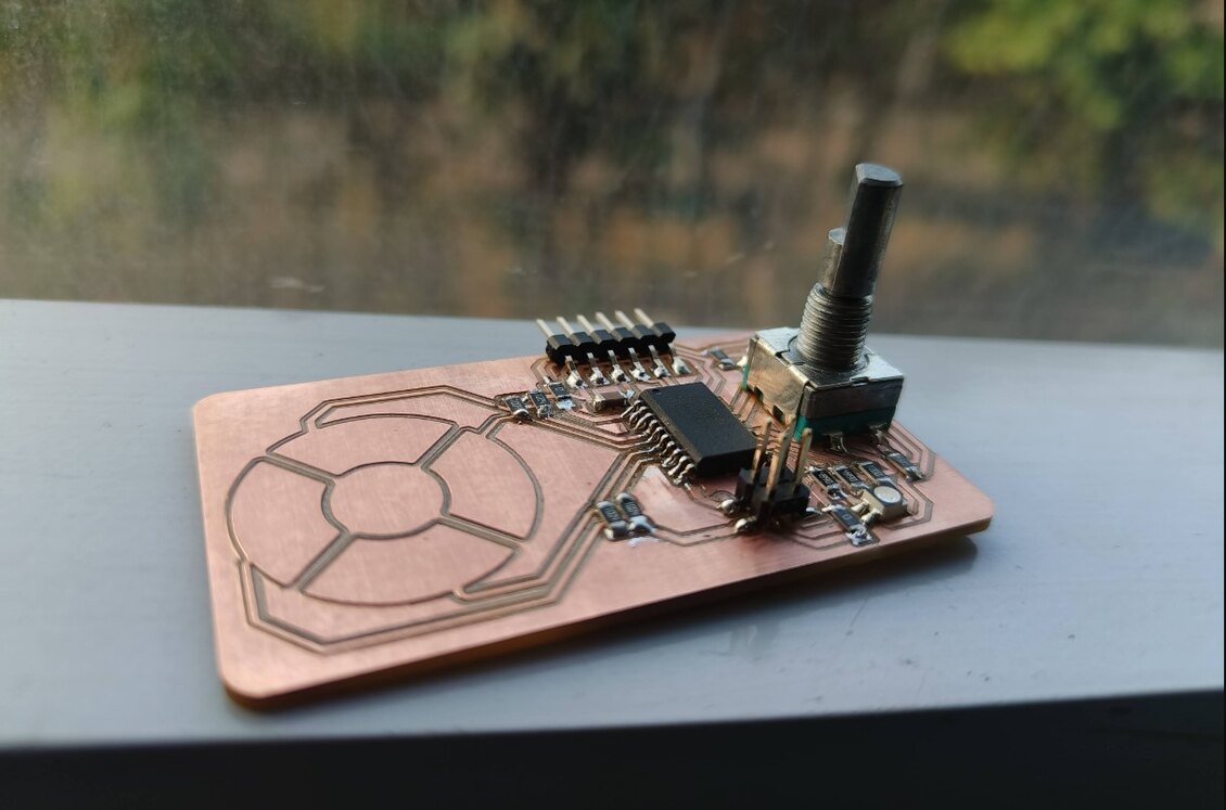
During this week I tested out two sensors to compare them and then see which would be better suited for my project. Mainly the objective of this week was to finalize a sensor device for navigating the menu of the gamepad . At the end i went with the rotary encoder as it was the easier option for navigating for the current version of my project.
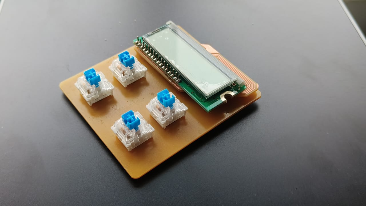
For this week i wanted to explore the output devices that would be required for my final project. I wondered if i could make a mini version of a module of my final project to test out the features. The output devices i wanted to use this week are :
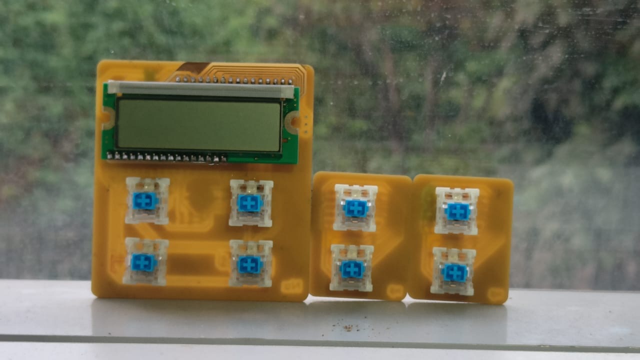
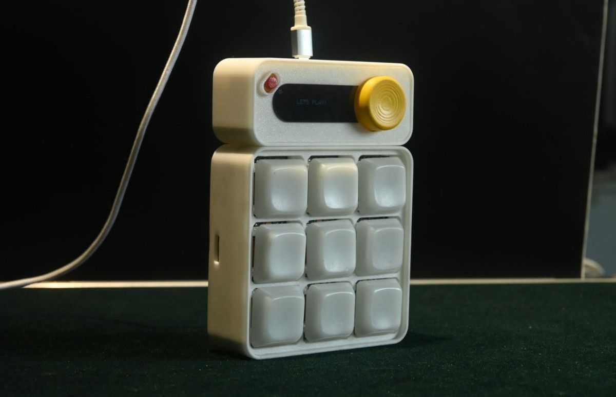
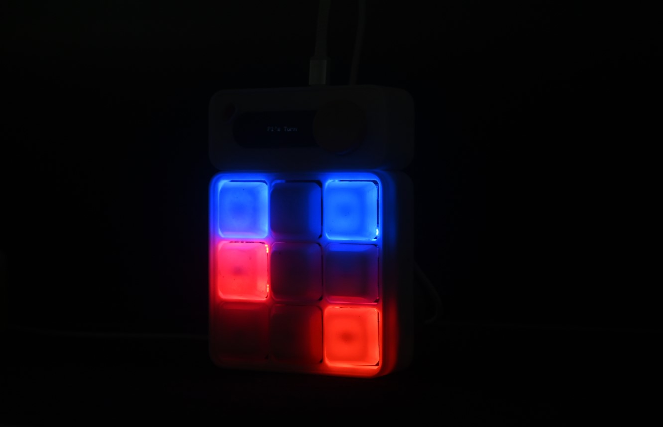
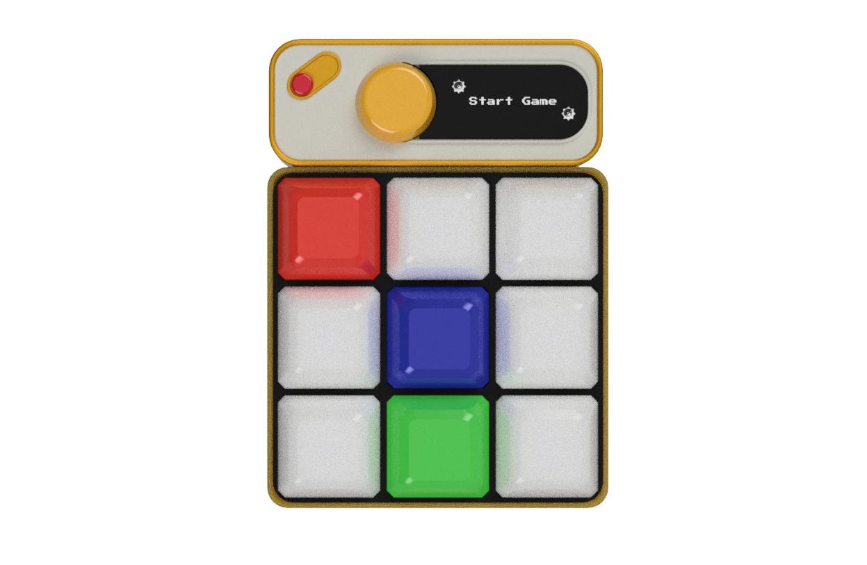
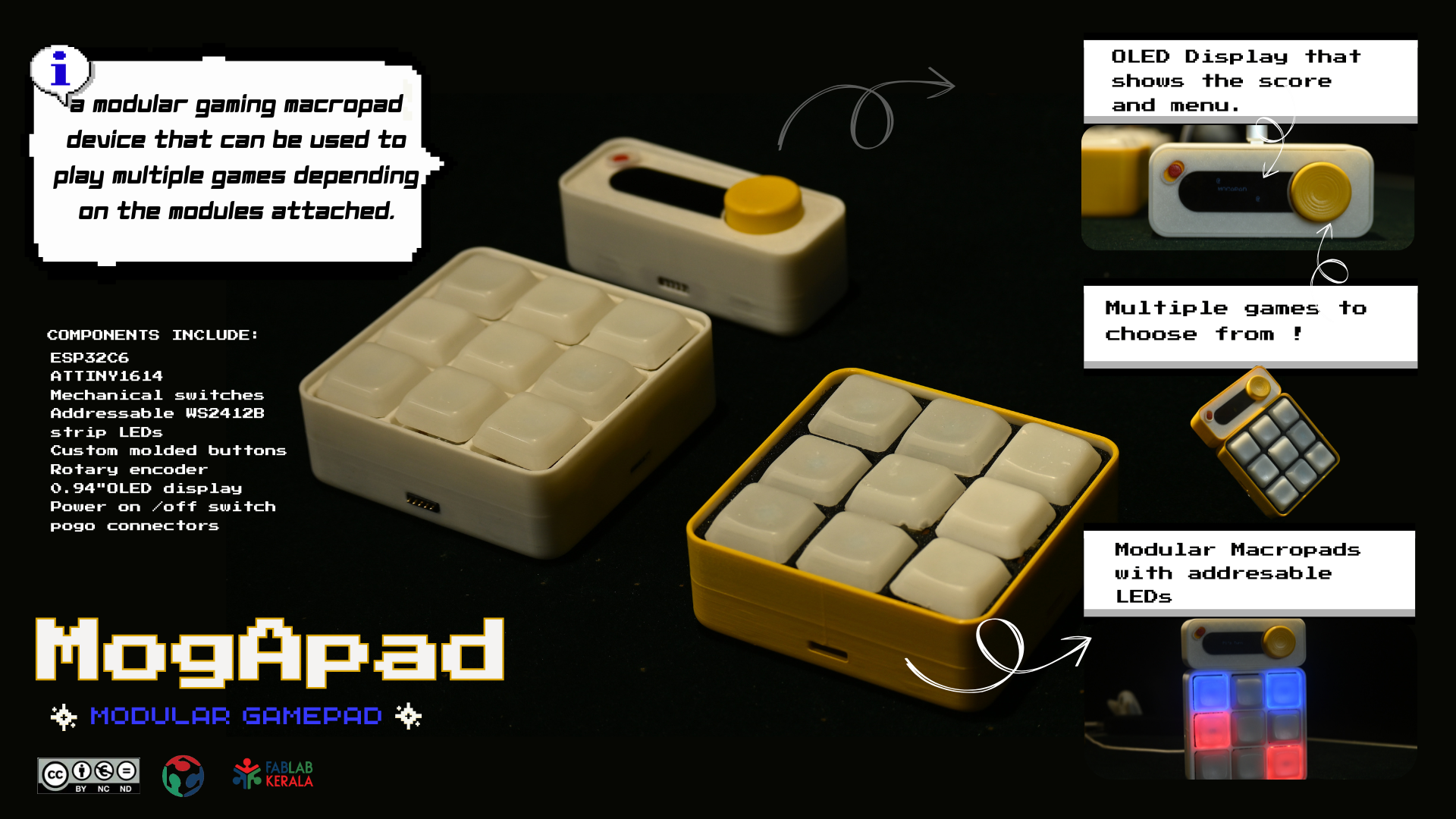
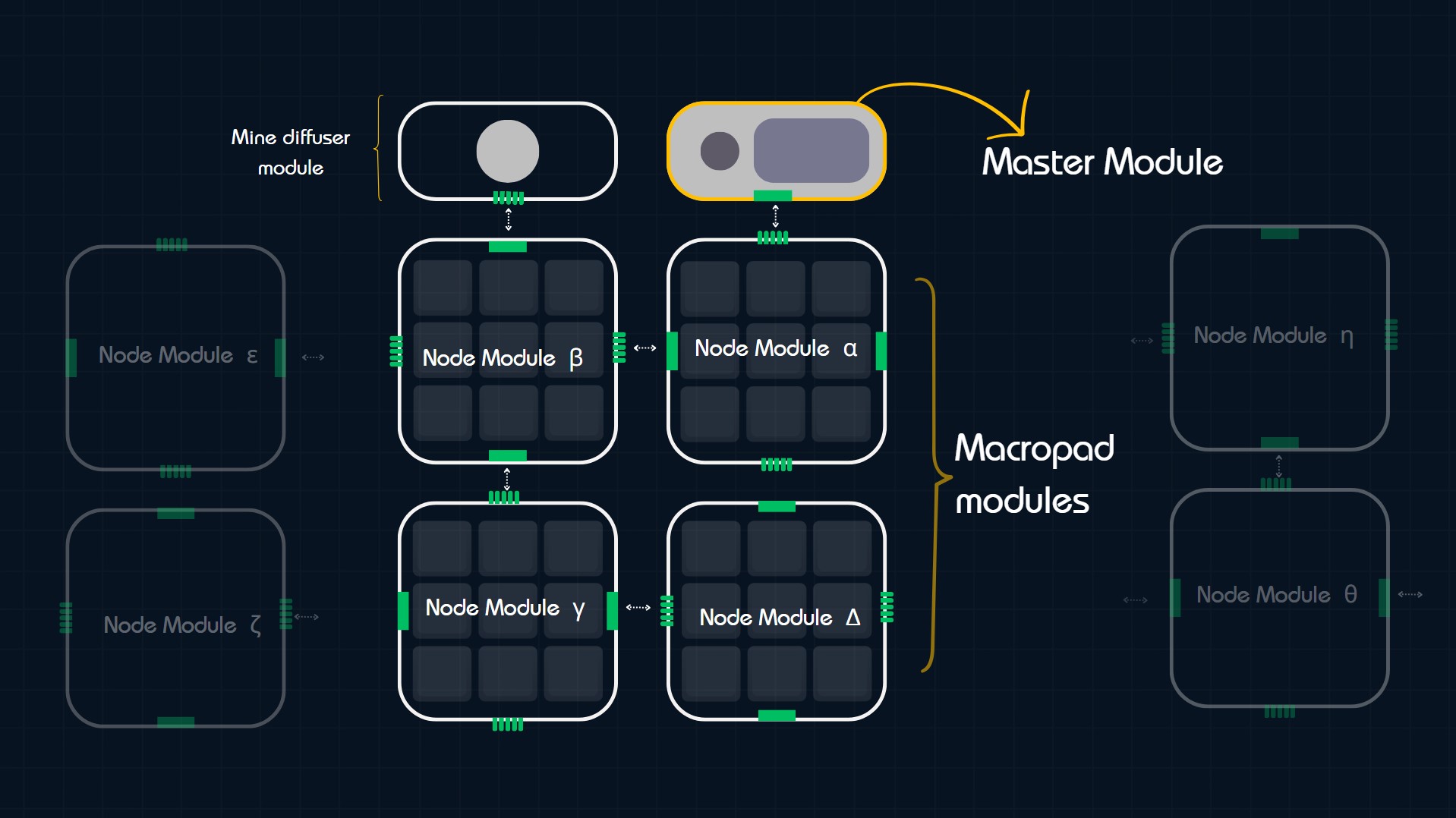
MogA is a modular gaming macropad device that can be used to play multiple games depending on the modules
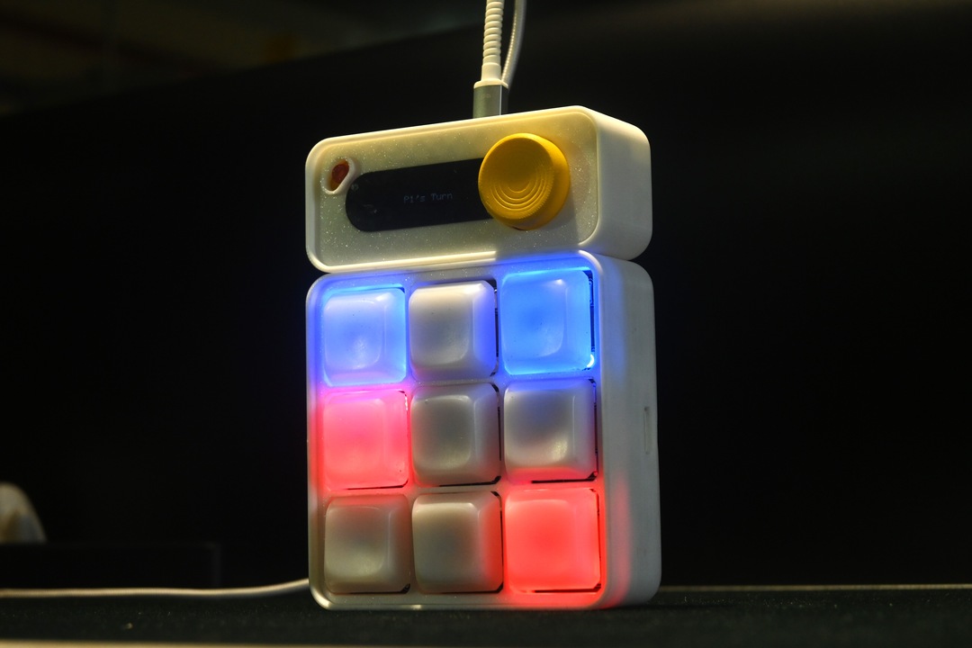
attached. It would run games like Minesweeper, Snake, and Tic Tac Toe depending on the modules connected. The keys
act as visual lighting feedback to play the games. The main inspiration of this project came from the game
Minesweeper. I wanted to make a physical version of the game. The Idea is that macropads can be rearranged with
various modules and compose different layouts using a magnetic connector system to play different games. The
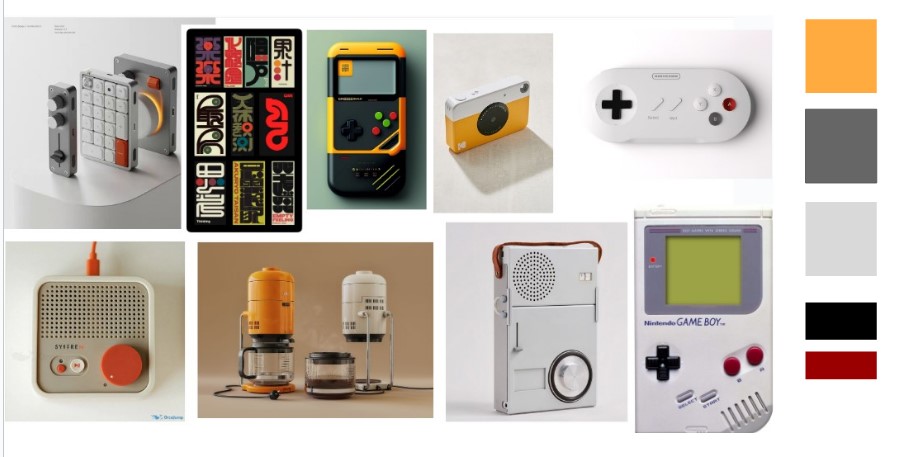
concept of making it into a physical gaming device stemmed from wanting to make a game console such as the
Nintendo Gameboy and switch, to bring back that era of handheld gaming .
Taking inspiration from keyboard macropads that are often used to automate repetitive actions, enhance gaming
workflows, or streamline media control, I wanted to customize it into a solitary gaming device. I haven't found
anything specifically made for a game , rather the macropads acted as mini keyboards for controlling something on
the computer.
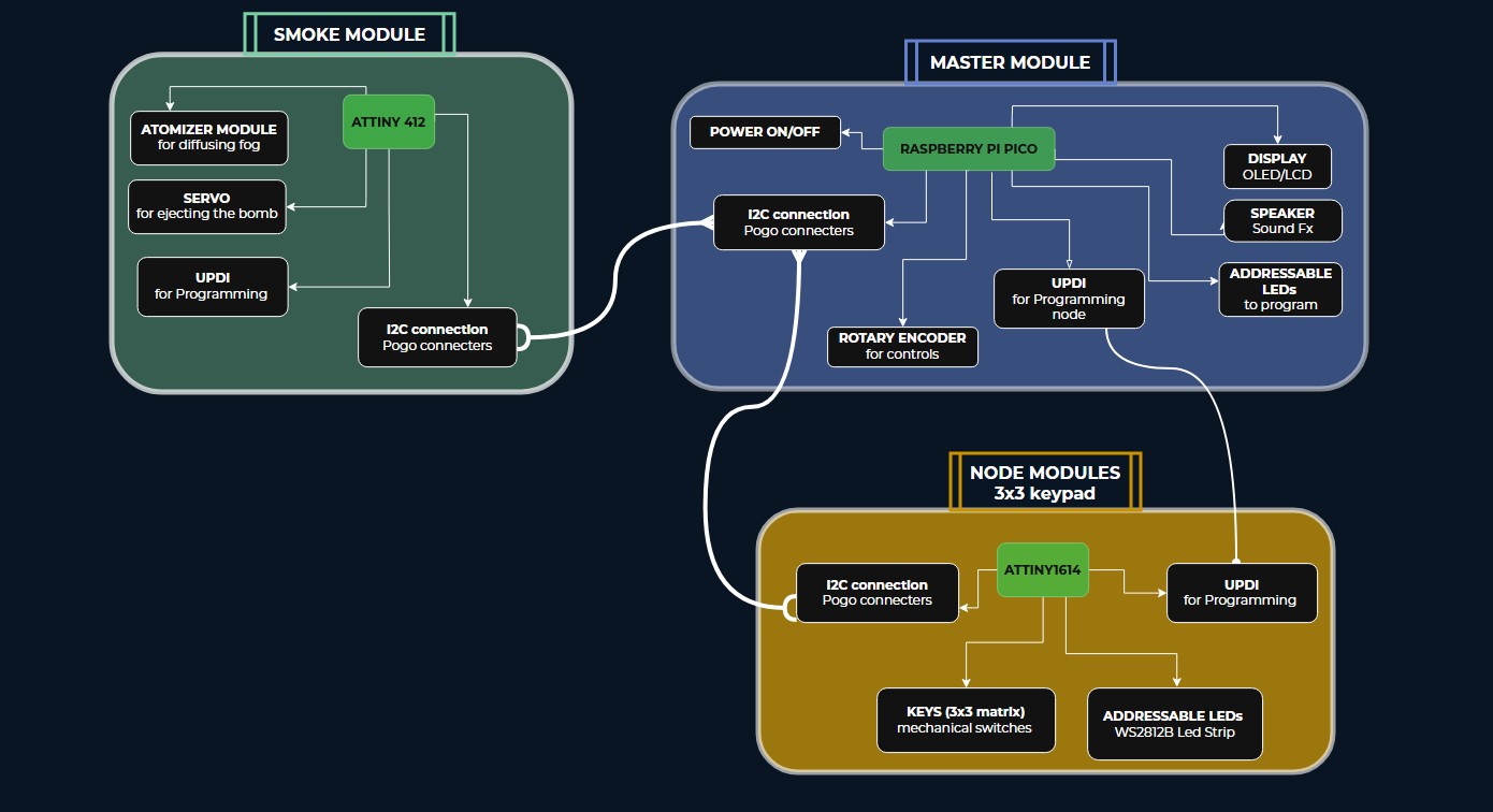
The project has 2 main components:
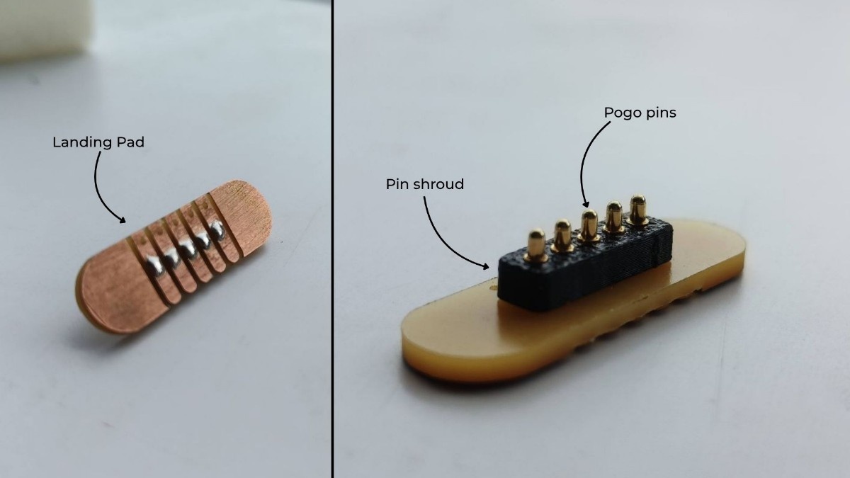
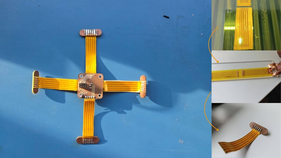
 In this Video I learned how to make DIY pogo connnectors. Saheen helped me to modify it to fit into our context of
the project.
Other sources were gathered throughout my fabacademy journey throughout the weeks.
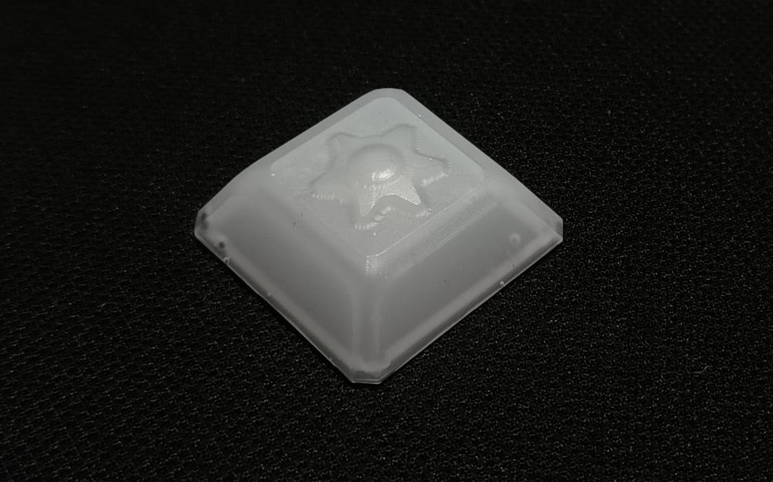
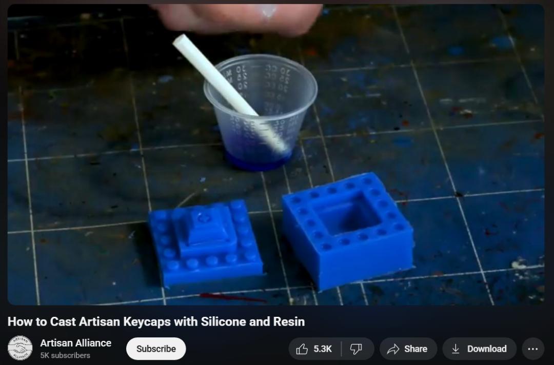
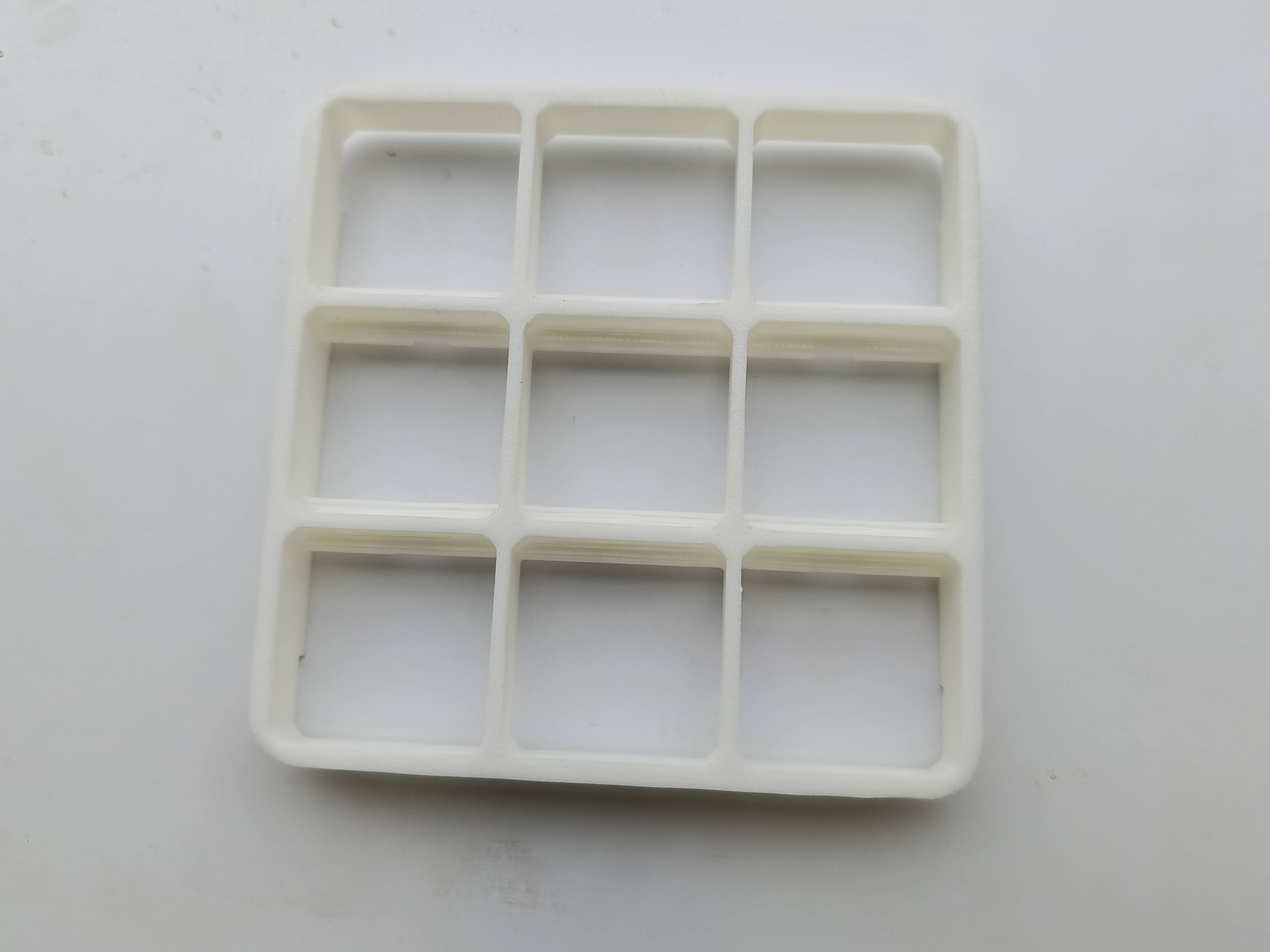
For making custom keycaps i referred to How to Cast Artisan Keycaps with Silicone and Resin by Artisan Alliance. It was
a thorough and informative video and explains the process very well.
In this Video I learned how to make DIY pogo connnectors. Saheen helped me to modify it to fit into our context of
the project.
Other sources were gathered throughout my fabacademy journey throughout the weeks.
For making custom keycaps i referred to How to Cast Artisan Keycaps with Silicone and Resin by Artisan Alliance. It was
a thorough and informative video and explains the process very well.
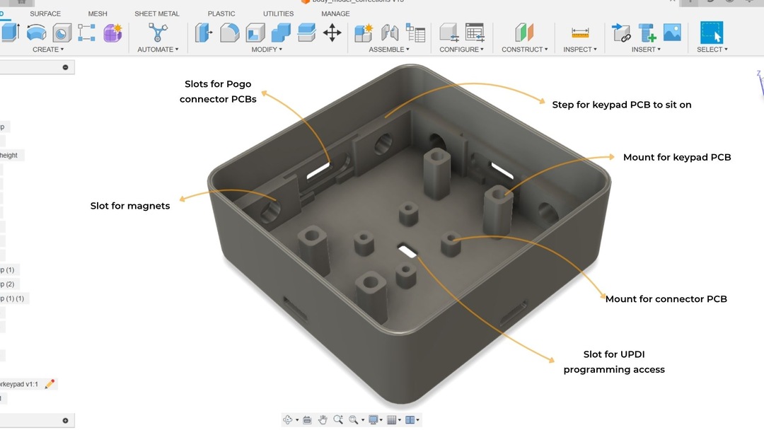
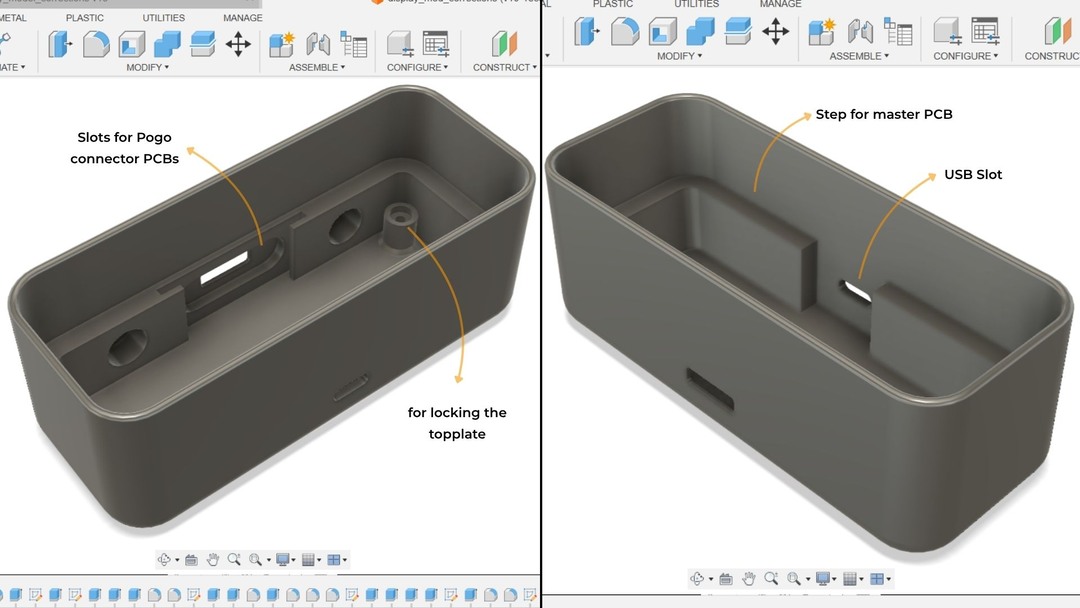
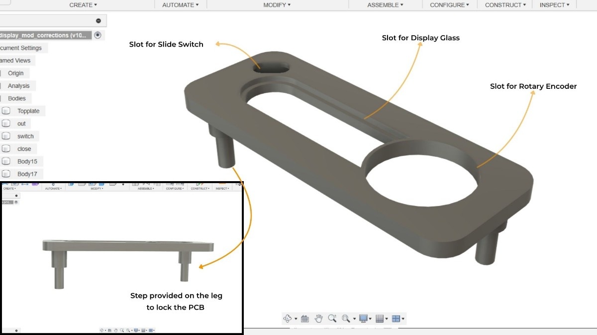
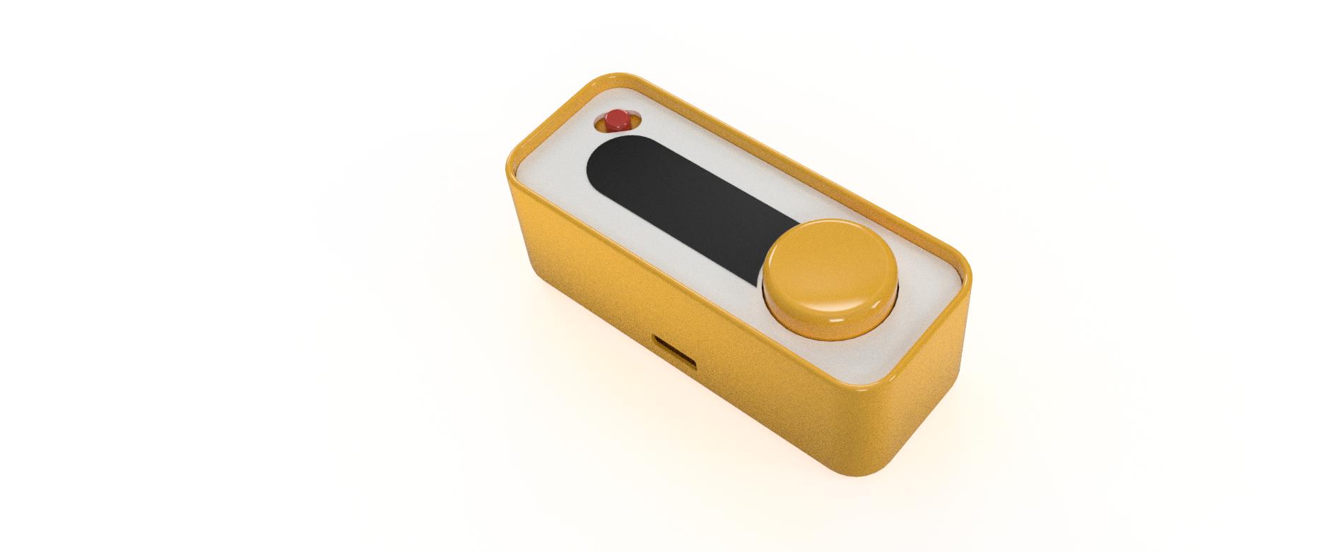
I did the CAD modelling of the node and the master modules in Fusion360. The whole process had to go through a
lot
of iterations as the 3d models and the electronics were interconnected with each other. The biggest challenge came
while trying to integrate all the components with in the dimensional constraints.
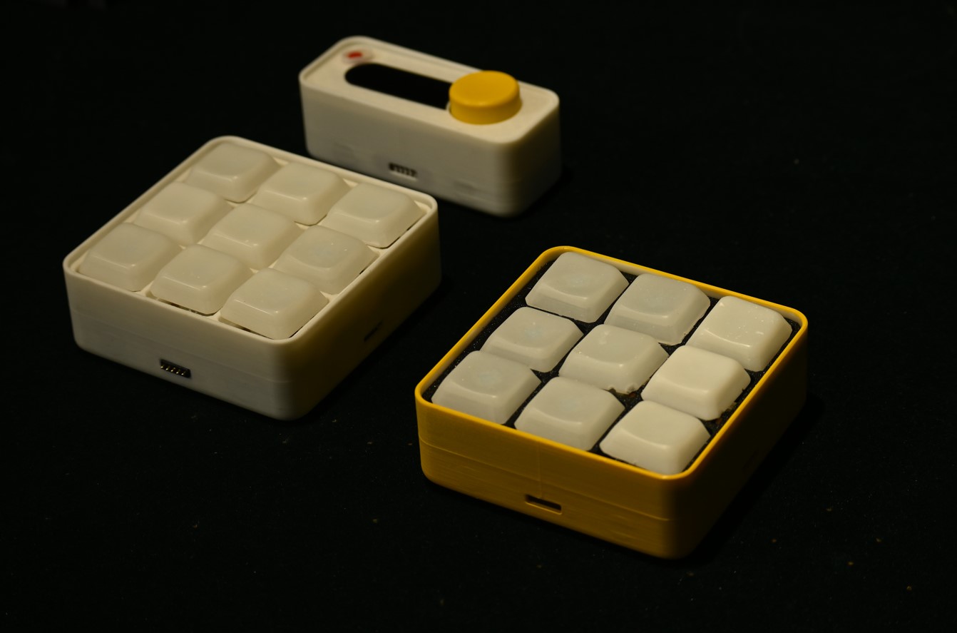
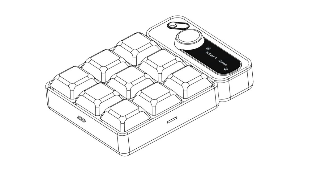
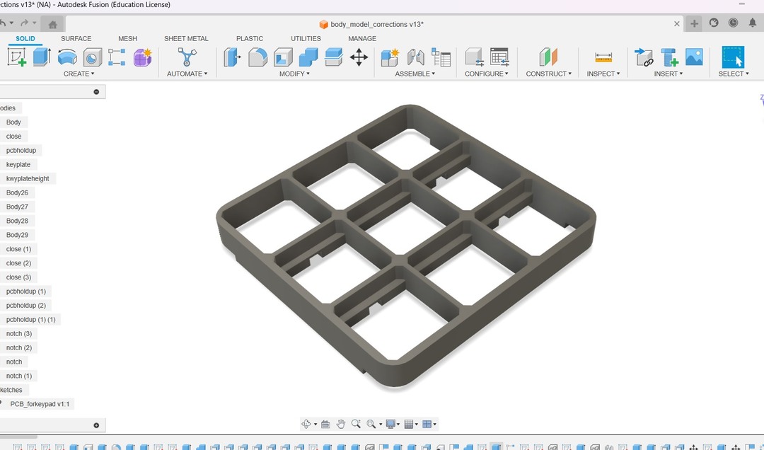
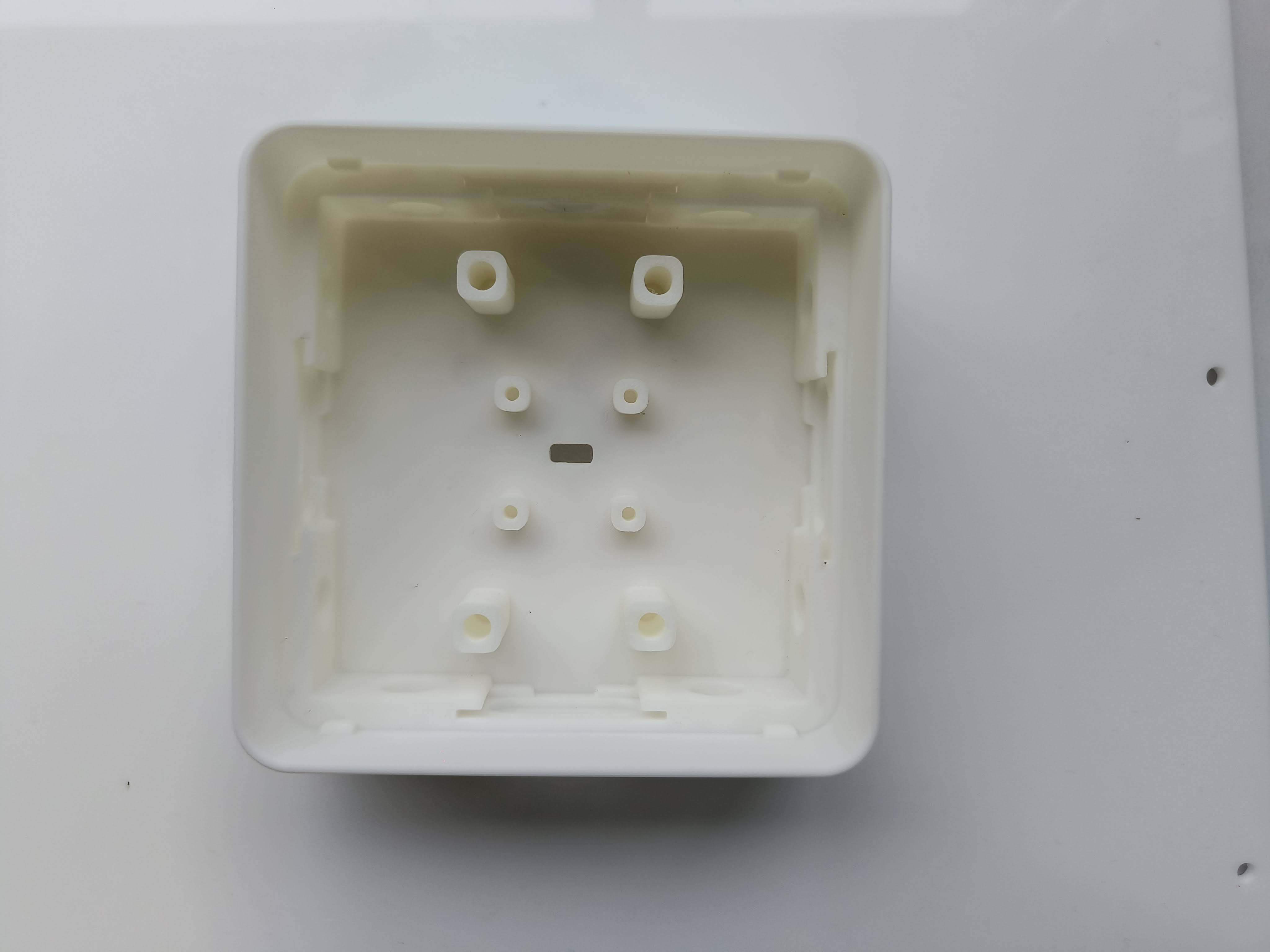
I started off by designing the node module . I wanted to keep the dimension of the node to be that of a module
that
can be held in your hand. At the same time the buttons had to be the highlight and i didn't want to give the
module
the look of a typical macropad. As the function of my keypad is to play games i wanted to emulate that feeling to
the module by keeping the keycaps a little larger in size than the typical keycaps. I had to make a lot of
iterations to arrive at this final design. i went back and forth with the electronics design to make sure
everything
fit with each other.
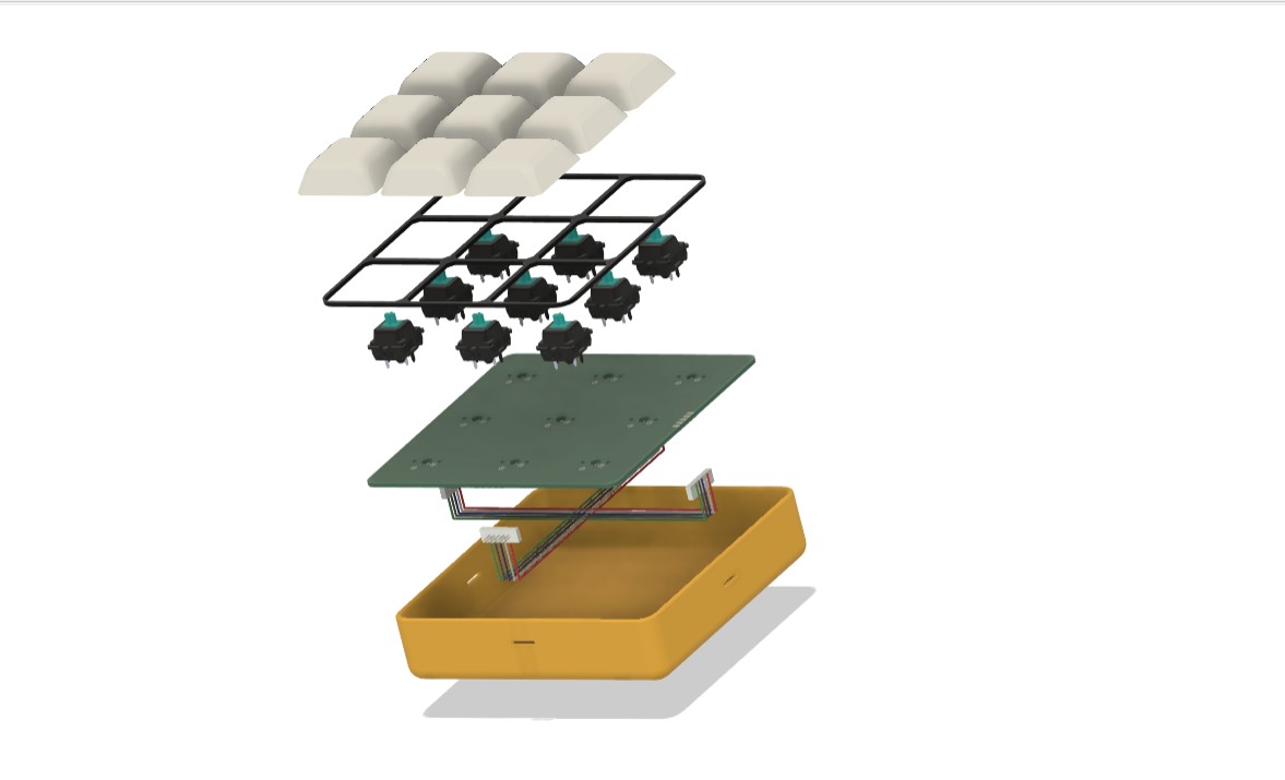
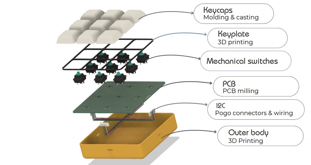
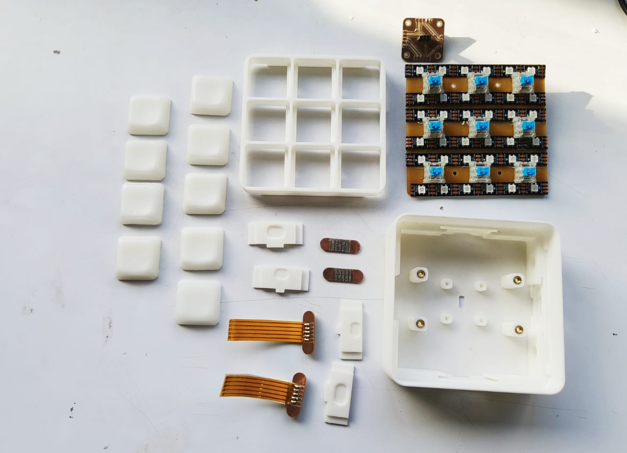
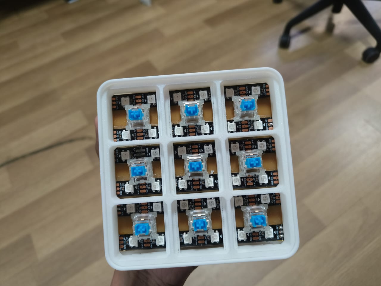
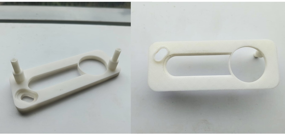
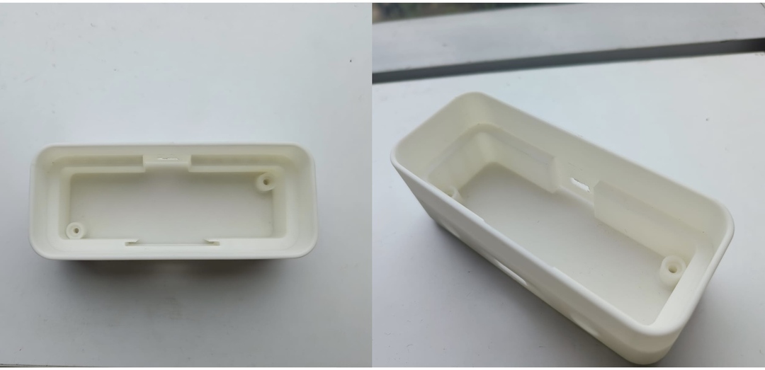
The parts of this module consists of :
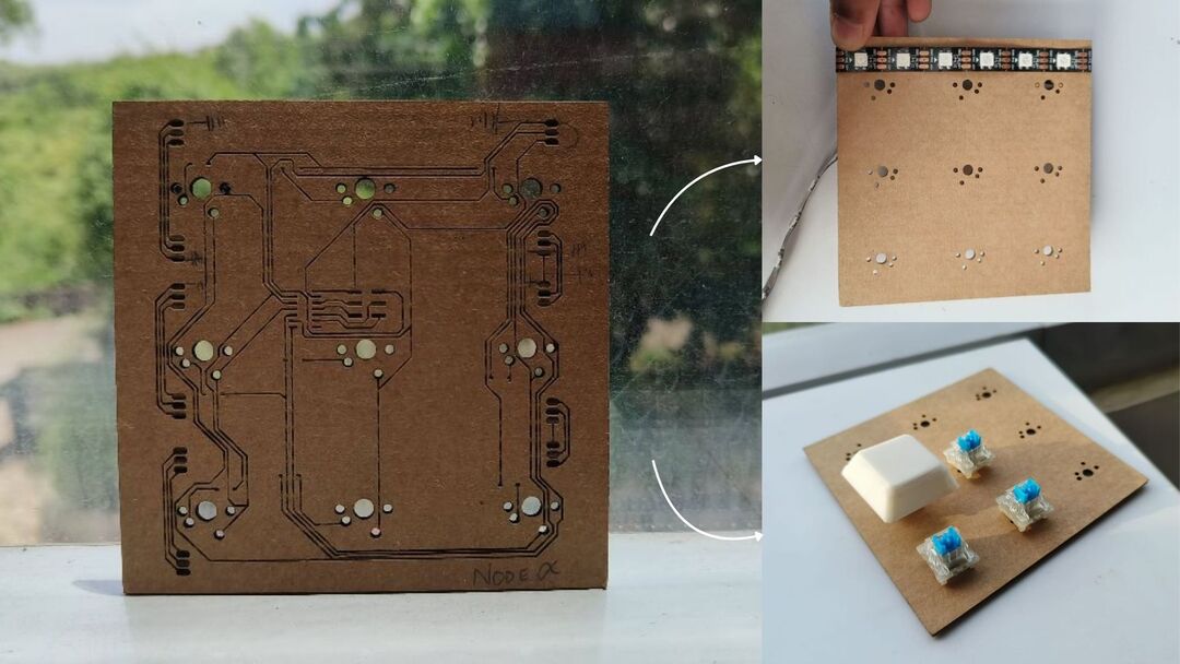
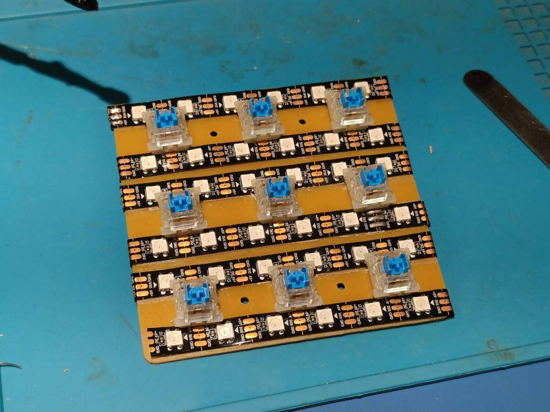
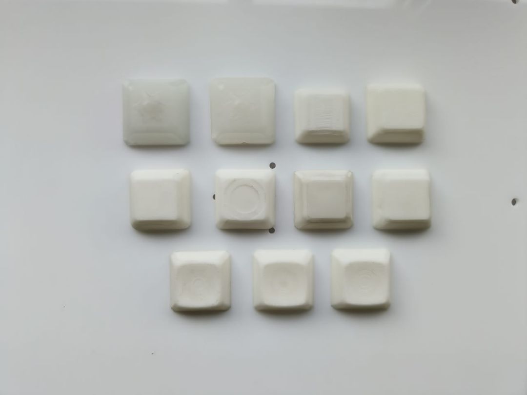
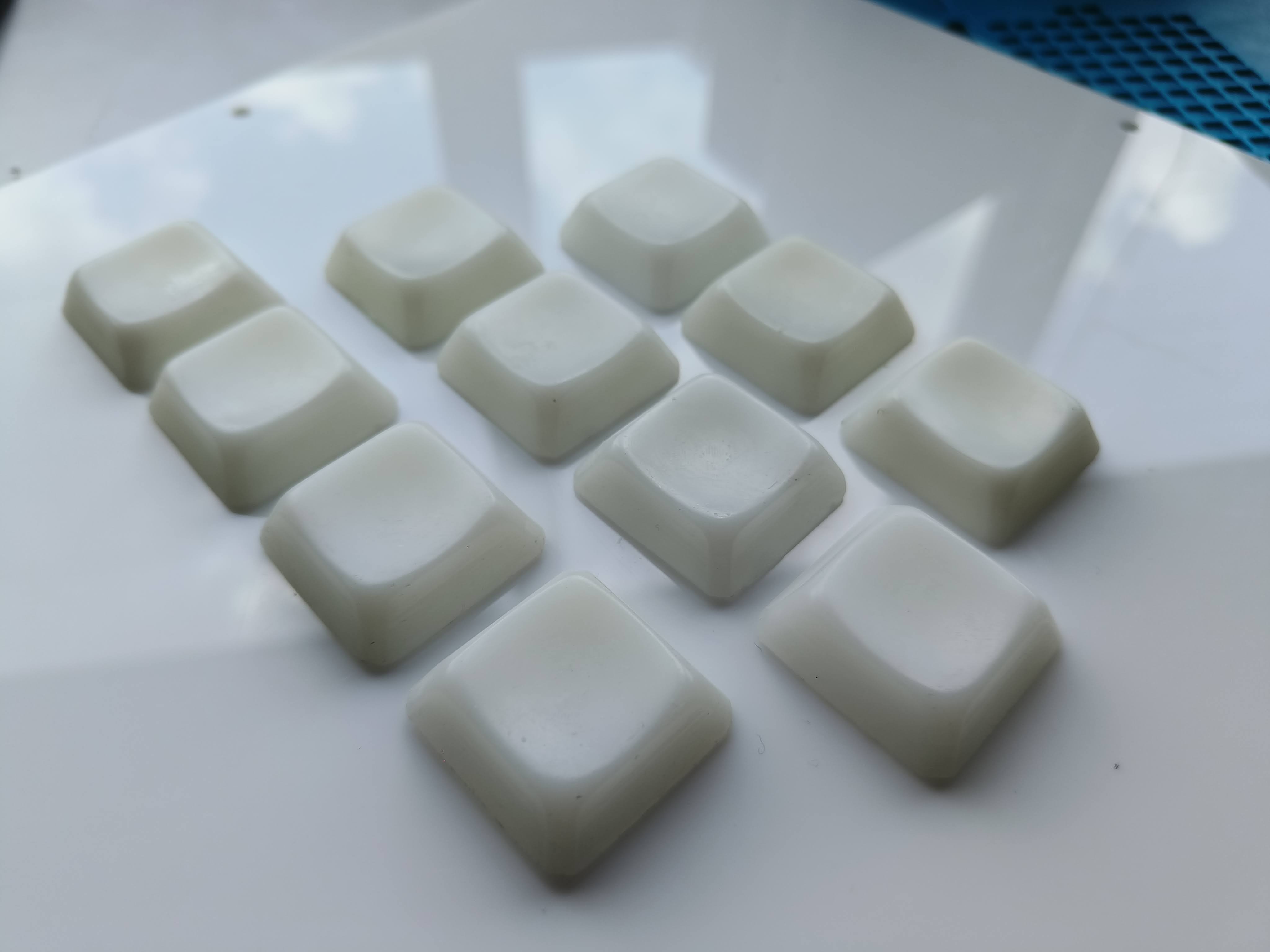
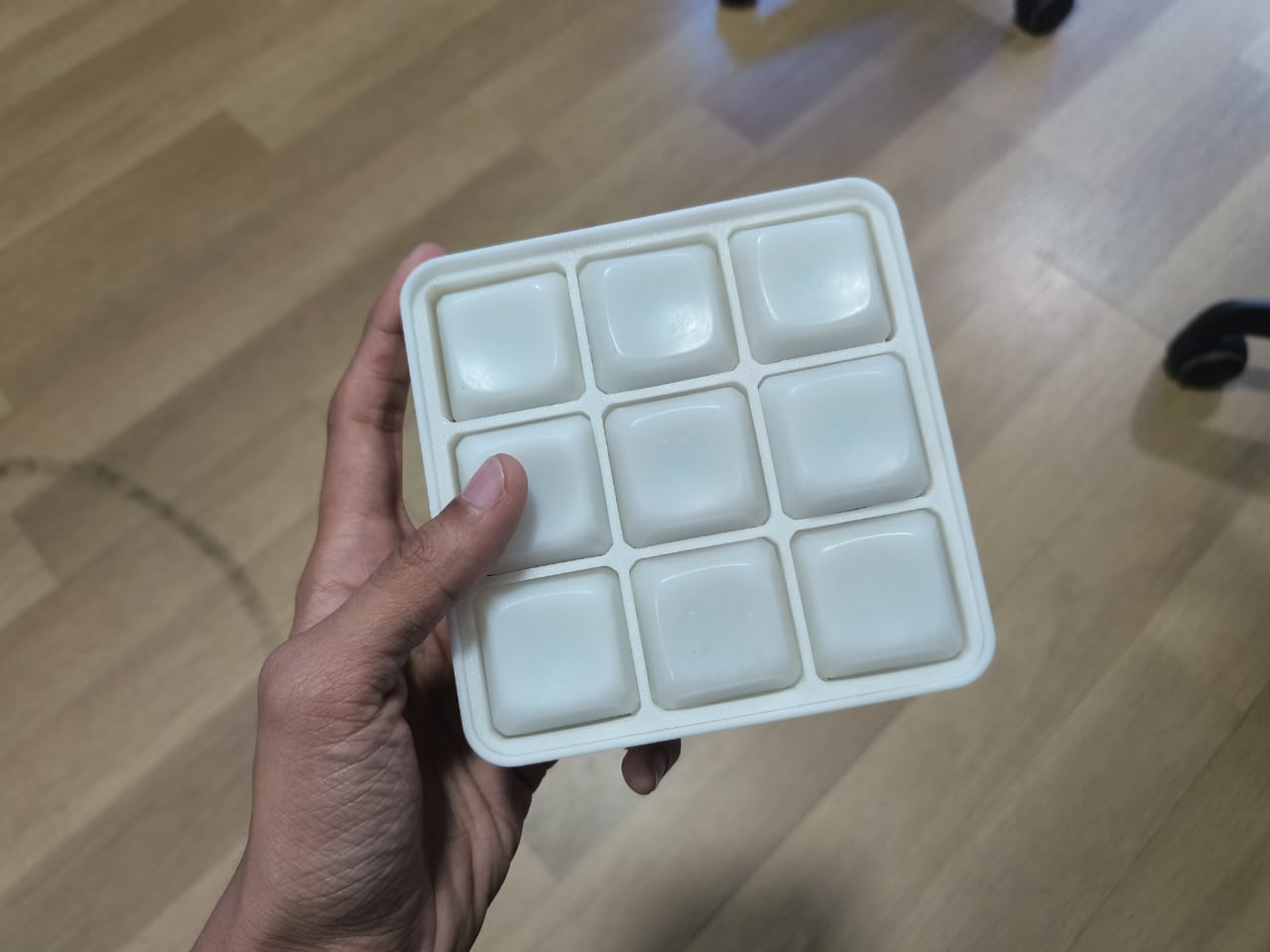
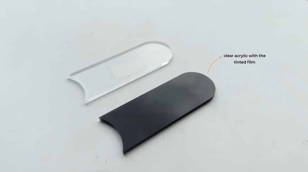
 The Keycaps : the buttons are inspired from the minesweeper tiles . I wanted the physical buttons match the
appearance of the digital counterpart.
The Keycaps : the buttons are inspired from the minesweeper tiles . I wanted the physical buttons match the
appearance of the digital counterpart.
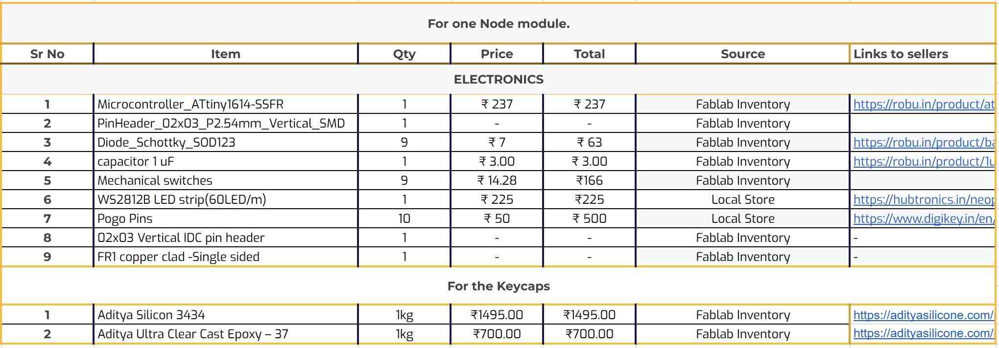
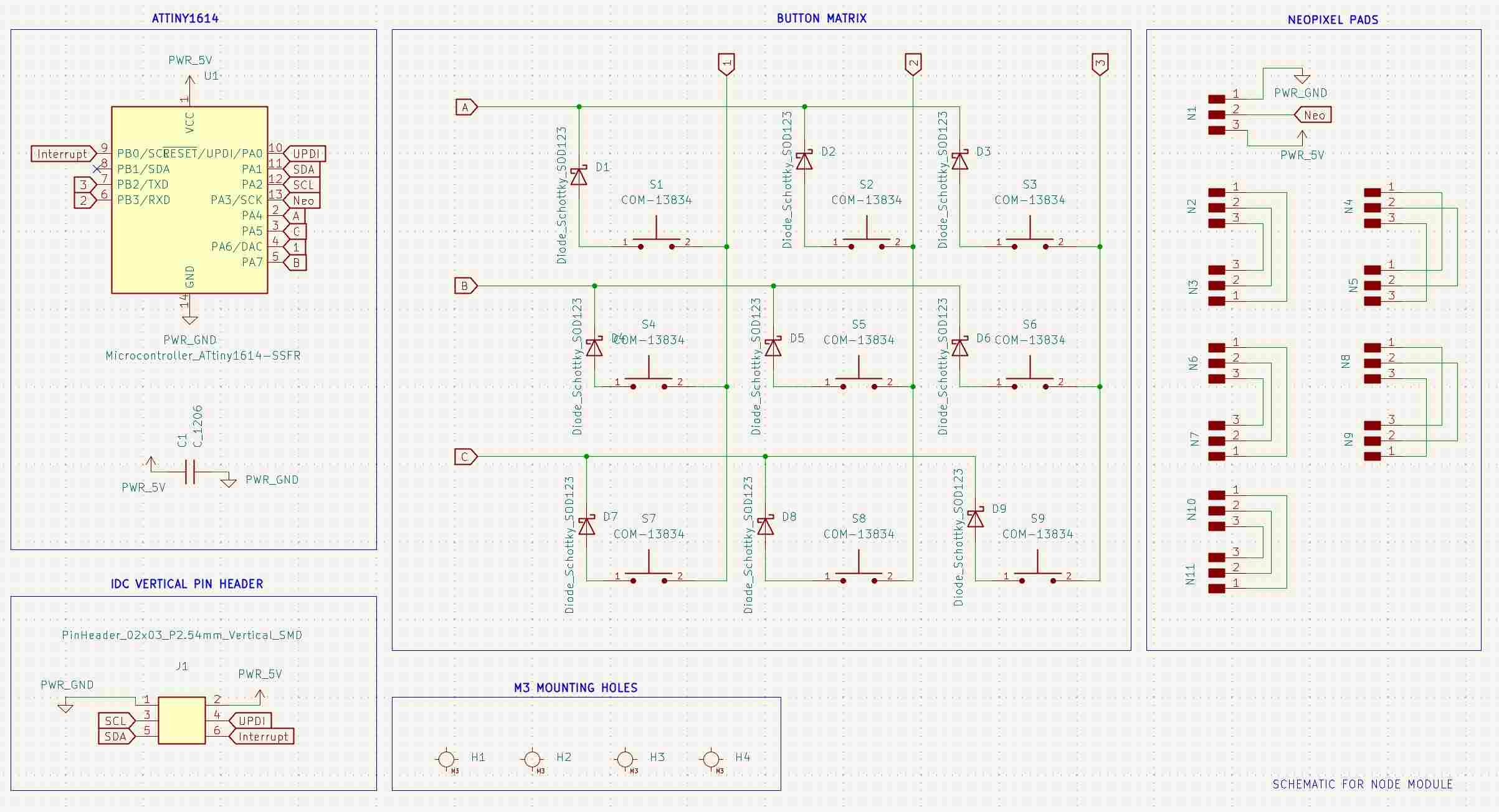
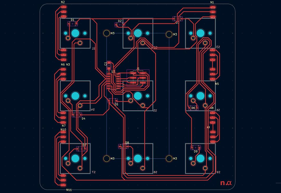
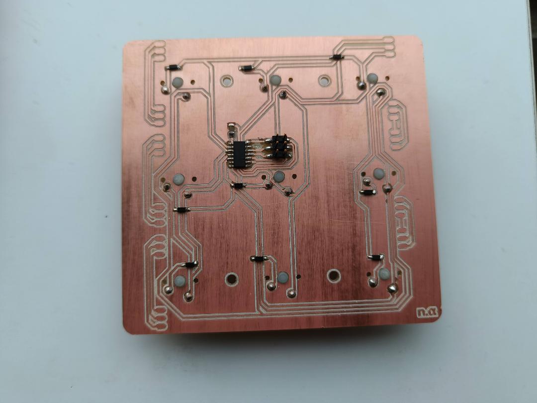
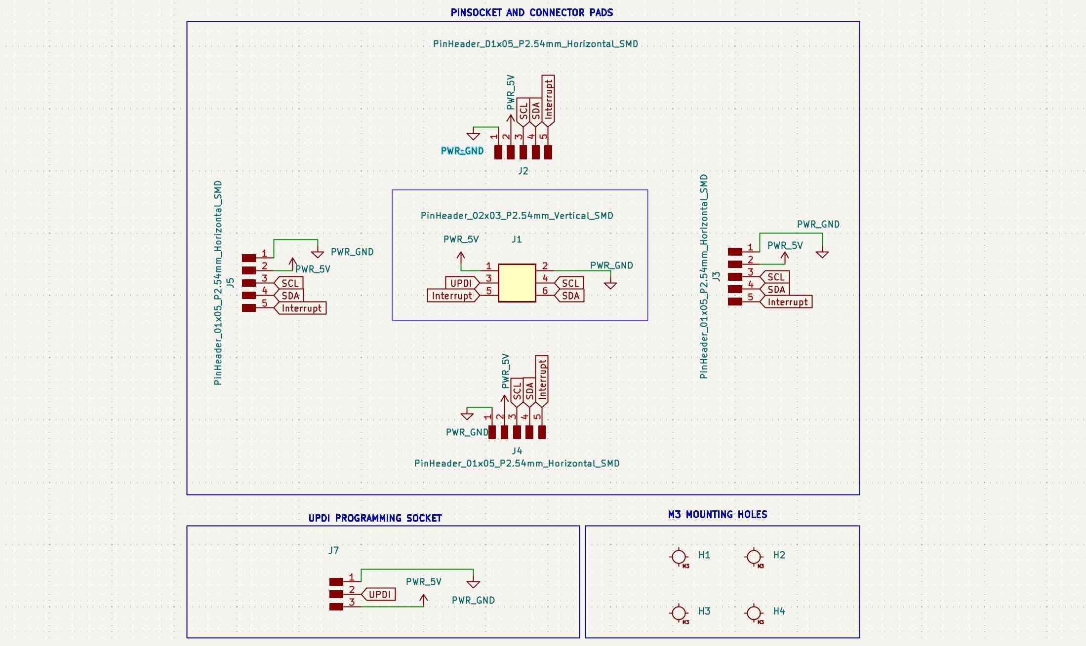
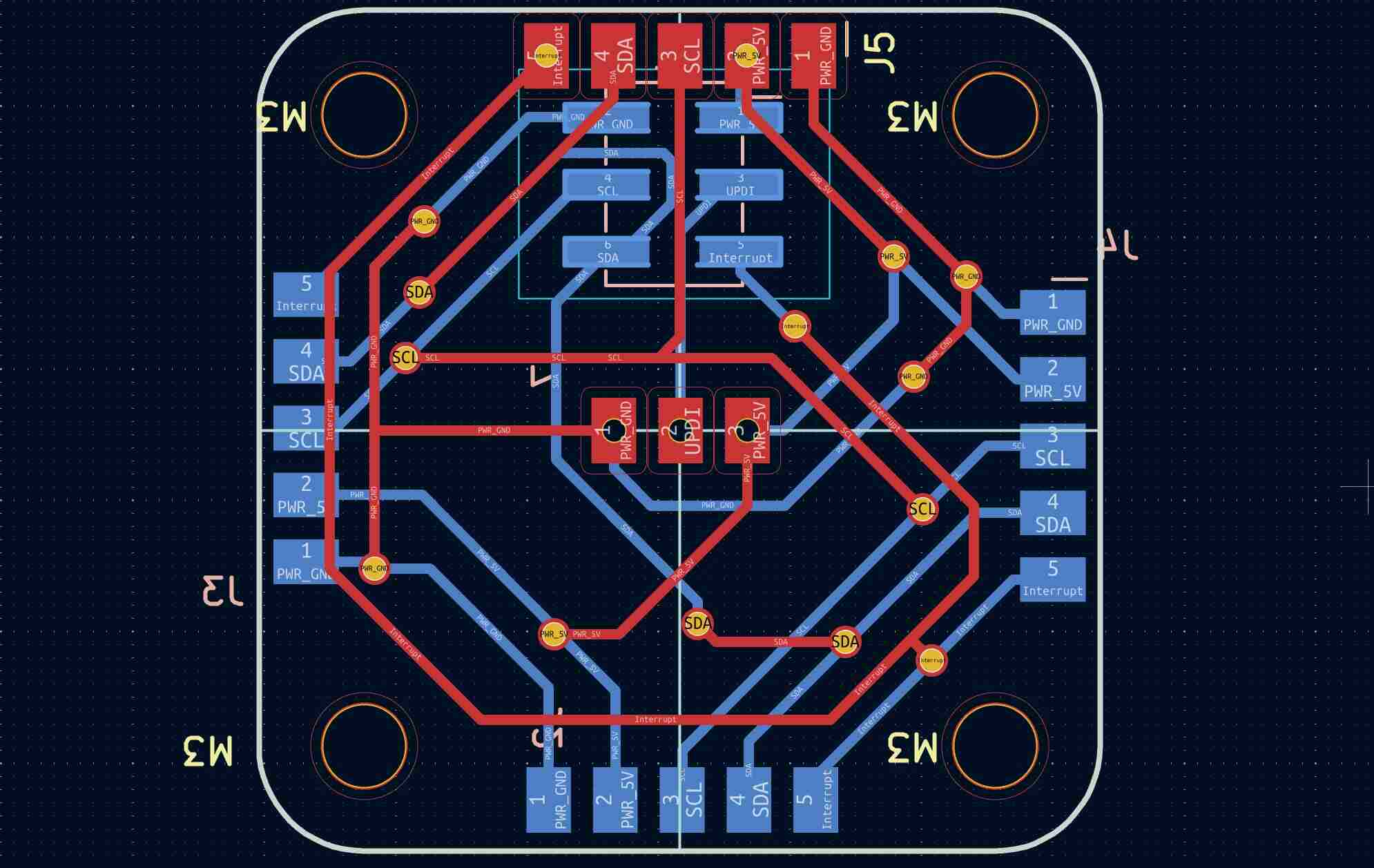
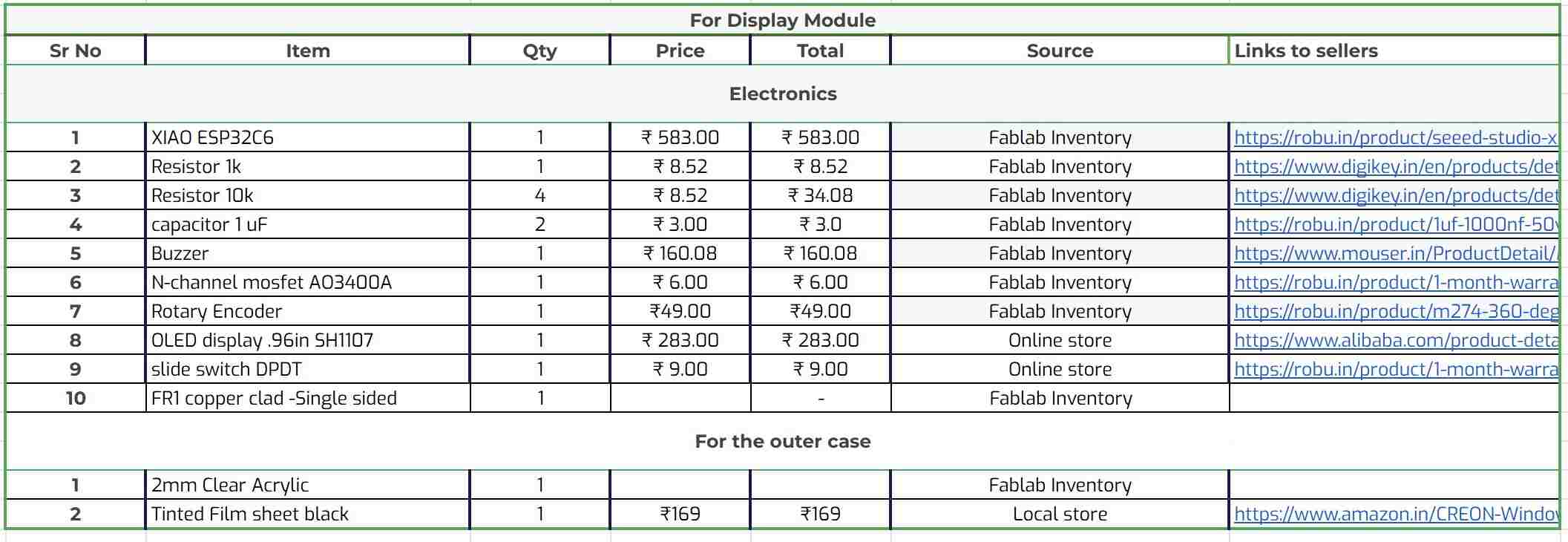
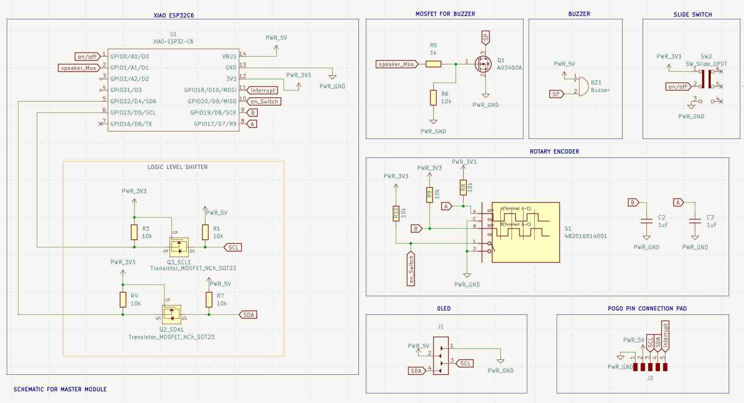
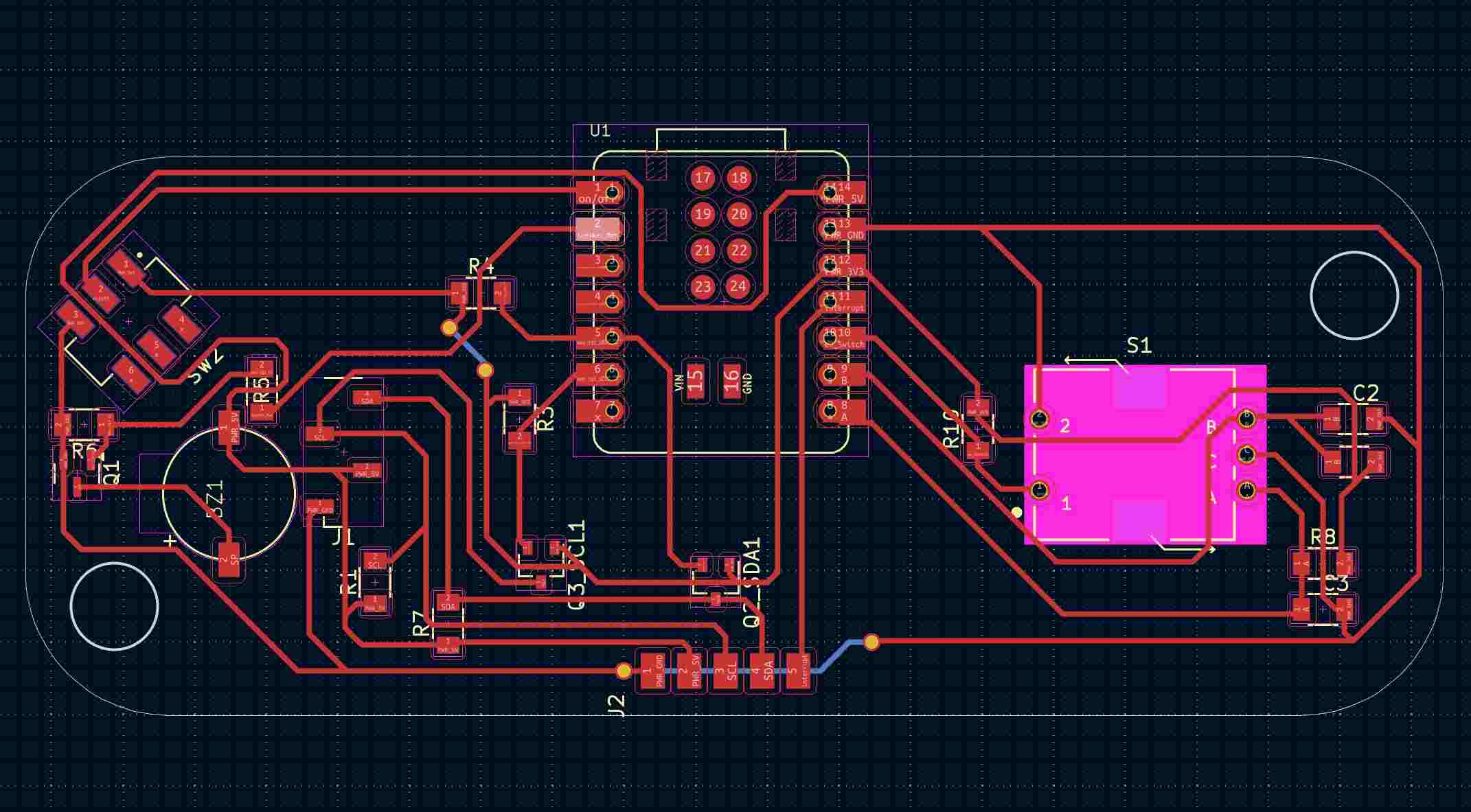
I started the electronics production of the project with the node module. The board has:
//Code by Namita made for MogApad
//Code for turning on the corresponding addressable LEDs according to the switch that is being pressed

#include <Keypad.h>
#include <SoftwareSerial.h>
#include <Adafruit_NeoPixel.h>
#ifdef __AVR__
#include <avr/power.h>  // Required for 16 MHz Adafruit Trinket
#endif

#define LED_PIN 10  //Led Pin

// How many NeoPixels are attached?
#define LED_COUNT 36

Adafruit_NeoPixel strip(LED_COUNT, LED_PIN, NEO_GRB + NEO_KHZ800);

int getLED[9][4] = {  // Matrix of number of switches x the corresponding 4 Leds

  { 0, 1, 11, 10 },  // Led addresses of Switch 1
  { 2, 3, 9, 8 },    // Led addresses of Switch 2 and so on
  { 4, 5, 7, 6 },
  { 12, 13, 23, 22 },
  { 14, 15, 21, 20 },
  { 16, 17, 19, 18 },
  { 24, 25, 35, 34 },
  { 26, 27, 33, 32 },
  { 28, 29, 31, 30 }


};

bool ledStatus[36];  //Array of the Leds

SoftwareSerial mySerial(PIN_PA2, PIN_PA1);  // RX, TX

const byte ROWS = 3;  //three rows
const byte COLS = 3;  //three columns

//Assigning a number to each of the switches of the matrix keypad
char hexaKeys[ROWS][COLS] = {
  { '2', '5', '8' },
  { '1', '4', '7' },
  { '0', '3', '6' }


};

byte rowPins[ROWS] = { 2, 4, 5 };  //connect to the row pinouts of the keypad
byte colPins[COLS] = { 0, 3, 1 };  //connect to the column pinouts of the keypad

//initialize an instance of class NewKeypad
Keypad customKeypad = Keypad(makeKeymap(hexaKeys), rowPins, colPins, ROWS, COLS);

void setup() {
  mySerial.begin(4800);

  // LED
  strip.begin();            // INITIALIZE NeoPixel strip object (REQUIRED)
  strip.show();             // Turn OFF all pixels ASAP
  strip.setBrightness(50);  // Set BRIGHTNESS to about 1/5 max = 255
  strip.clear();
}

void loop() {
  // mySerial.println("Hello");
  // delay(500);
  int key = getkey();
  showkey(key, strip.Color(127, 0, 0));
  //  theaterChase(strip.Color(127, 127, 127), 50);
}
int getkey() { //To show which key is beign pressed on the serial monitor
  char customKey = customKeypad.getKey();

  if (customKey) {
    mySerial.println(customKey);
    return (((String)customKey).toInt());
  }
  return (-1);
}


void showkey(int key, uint32_t color) {  // To light up the Leds
  for (int i = 0; i < 4; i++) {
    strip.setPixelColor(getLED[key][i], color);
  }
  strip.show();
}
As said before the idea to DIY the pogo connectors came from "Salim Benbouziyane ‘s". video.

//Code for MogApad Master Board with ESP32C6
#include <SPI.h>
#include <Wire.h>
#include <Adafruit_GFX.h>
#include <Adafruit_SH110X.h>
// Encoder pins
#define ENCODER_B D8
#define ENCODER_A D7
#define ENCODER_BUTTON D2
#define BUZZER_PIN D1 //buzzer
#define ONOFF_SWITCH D0 // On off switch
#define INTRUPT_PIN D10
bool powerStatus = false;
bool powerUpdate = false;
bool gameStatus = false;
int gameMode = 0;
bool gameFinished = false;
//Encoder
volatile int Mode = 0;
volatile bool aState, bState;
volatile int lastEncoded = 0;
volatile boolean TurnDetected;
volatile boolean up;
volatile boolean intDetected;
int player = 1;
int n, i, e = 0, j = 0;
char a[9] = { '1', '2', '3', '4', '5', '6', '7', '8', '9' };
// char key;
int w = 0;
bool keyPressed = false;
int KeyData;
Adafruit_SH1107 display = Adafruit_SH1107(64, 128, &Wire);
//Encoder Function
void IRAM_ATTR readEncoder() {
// aState = digitalRead(ENCODER_A);
// bState = digitalRead(ENCODER_B);
TurnDetected = true;
up = (digitalRead(ENCODER_A) == digitalRead(ENCODER_B));
// if (aState == bState) {
// Mode++;
// } else {
// Mode--;
// }
}
void IRAM_ATTR readRead() {
Serial.println("requsting to read");
intDetected = true;
}
void setup() {
intDetected = false;
pinMode(ONOFF_SWITCH, INPUT);
pinMode(ENCODER_A, INPUT);
pinMode(ENCODER_B, INPUT);
pinMode(ENCODER_BUTTON, INPUT);
pinMode(INTRUPT_PIN, INPUT_PULLUP);
attachInterrupt(digitalPinToInterrupt(ENCODER_B), readEncoder, RISING);
// attachInterrupt(digitalPinToInterrupt(ENCODER_A), readEncoder, FALLING);
attachInterrupt(digitalPinToInterrupt(INTRUPT_PIN), readRead, RISING);
Serial.begin(115200);
Wire.begin(); // I2C Master
Serial.println("128x64 OLED FeatherWing test");
delay(250); // wait for the OLED to power up
display.begin(0x3C, true); // Address 0x3C default
// Show image buffer on the display hardware.
// Since the buffer is intialized with an Adafruit splashscreen
// internally, this will display the splashscreen.
// display.display();
delay(1000);
// Clear the buffer.
display.clearDisplay();
display.display();
display.setRotation(1);
// text display tests
display.setTextSize(2);
display.setTextColor(SH110X_WHITE);
display.setCursor(0, 0);
display.print("@");
display.setCursor(5, 25);
display.print("START GAME");
display.setCursor(115, 50);
display.print("@");
display.display(); // actually display all of the above
delay(1000);
display.clearDisplay();
display.display();
gameReset();
}
void loop() {
// Serial.println(digitalRead(ONOFF_SWITCH));
if (digitalRead(ONOFF_SWITCH) != powerStatus) {
if (!powerStatus) {
Serial.println("ON");
startup();
} else {
shutdown();
Serial.println("OFF");
}
powerStatus = digitalRead(ONOFF_SWITCH);
}
if (gameStatus) {
// Display OLED Chose game: XOX, mine Sweeper,
// select mode using Encoder
if (digitalRead(ENCODER_BUTTON) == LOW) {
display.display();
display.clearDisplay();
display.setCursor(5, 25);
Serial.println("OK");
display.print("LETS PLAY!");
display.display();
delay(300);
display.clearDisplay();
display.setCursor(5, 25);
display.print("LETS PLAY!");
display.display();
tone(BUZZER_PIN, 294, 500); // D4
delay(200); // Debounce delay
gameFinished = false;
gameReset();
if (Mode) {
gameMode = 1;
} else {
gameMode = 2;
}
}
if (TurnDetected) {
if (up) {
Mode = 1;
} else {
Mode = 0;
}
Serial.print("Mode: ");
Serial.println(Mode);
TurnDetected = false;
if (Mode) {
display.setTextSize(2);
display.clearDisplay();
display.display();
display.setCursor(0, 25);
display.print("TICTACTOE");
display.display();
} else {
display.setTextSize(2);
display.clearDisplay();
display.display();
display.setCursor(0, 25);
display.print("MINESWEEP");
display.display();
}
}
}
if (gameMode == 2) {
//Display OLED: "Connect more modeules"
}
// tic tac toe game function
if (gameMode == 1 && !gameFinished) {
if (keyPressed && player == 1) {
keyPressed = false;
sendCMD(KeyData + 48);
Serial.println("\nP1");
Serial.println(a[KeyData]);
a[KeyData] = 'X';
Serial.println(a[KeyData]);
w = check(a, KeyData);
if (w == 1) {
Serial.println("Player 1 Wins!");
display.clearDisplay();
display.setCursor(5, 25);
display.print("P1 Wins!");
display.display();
gameFinished = true;
startup_tone();
}
else
{
e++;
player++;
display.clearDisplay();
display.setCursor(5, 25);
display.print("P2's Turn");
display.display();
tone(BUZZER_PIN, 294, 500); // D4
delay(1000);
}
}
delay(20);
if (keyPressed && player == 2) {
sendCMD(KeyData + 48 + 10);
keyPressed = false;
Serial.println("\nP2");
Serial.println(a[KeyData]);
a[KeyData] = '0';
Serial.println(a[KeyData]);
w = check(a, KeyData);
Serial.println(w);
if (w == 2) {
Serial.println("Player 2 Wins!");
display.clearDisplay();
display.setCursor(5, 25);
display.print("P2 Wins!");
display.display();
gameFinished = true;
startup_tone();
// tone(BUZZER_PIN, 294, 500); // D4
}
else
{
player--;
display.clearDisplay();
display.setCursor(5, 25);
display.print("P1's Turn");
display.display();
tone(BUZZER_PIN, 294, 500); // D4
delay(1000);
}
}
if (e == 5) {
Serial.println("Game Draw");
display.clearDisplay();
display.setCursor(5, 25);
display.print("Game Draw!");
display.display();
gameFinished = true;
gamefail_tone();
}
delay(20);
}
if (intDetected) {
getStatus();
intDetected = false;
}
}
void shutdown() {
gameStatus = false;
//Play Melady
shutdown_tone();
display.clearDisplay();
display.display();
gameMode = 0;
gameReset();
sendCMD(48 + 30);
delay(3000);
sendCMD(48 + 20);
//Lightup: Breathing RED LEDS
// turn off Modules
}
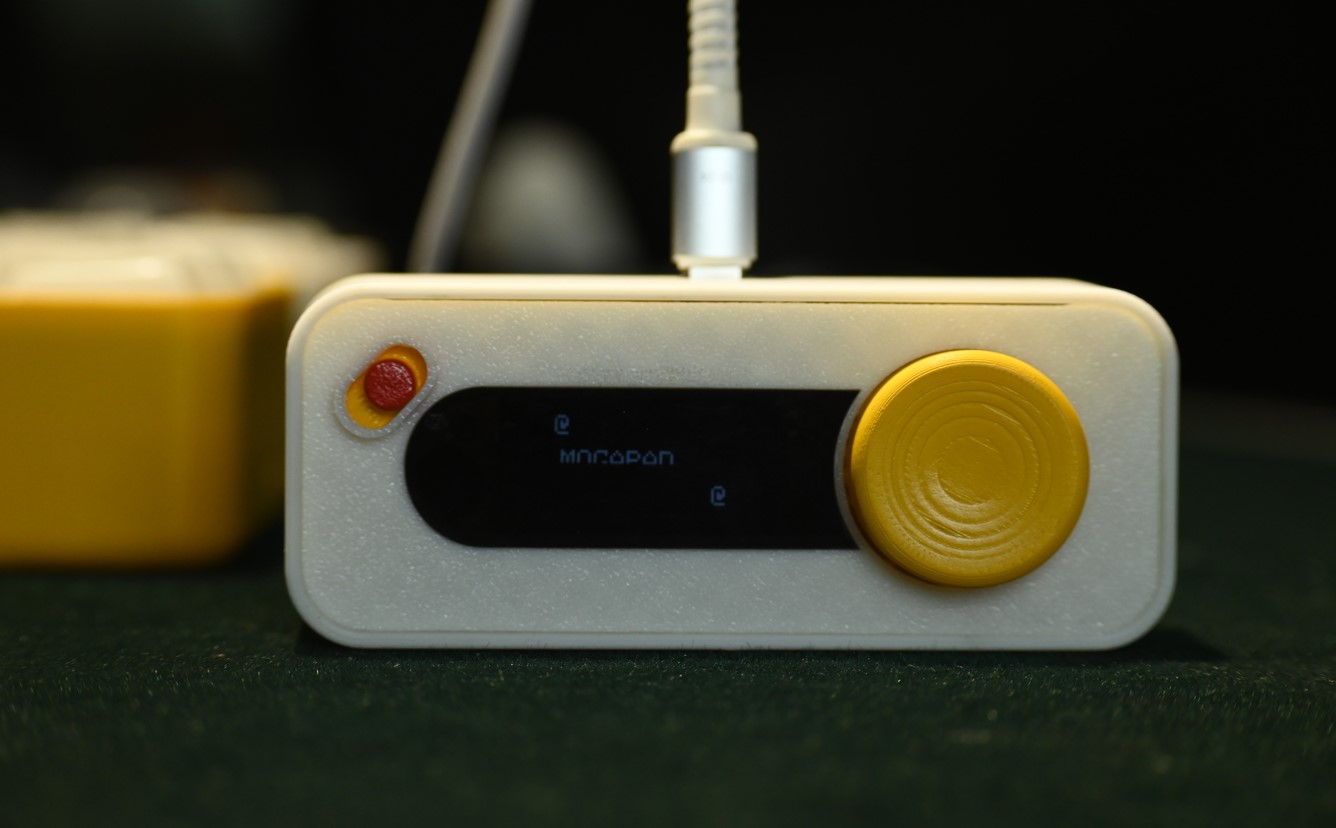
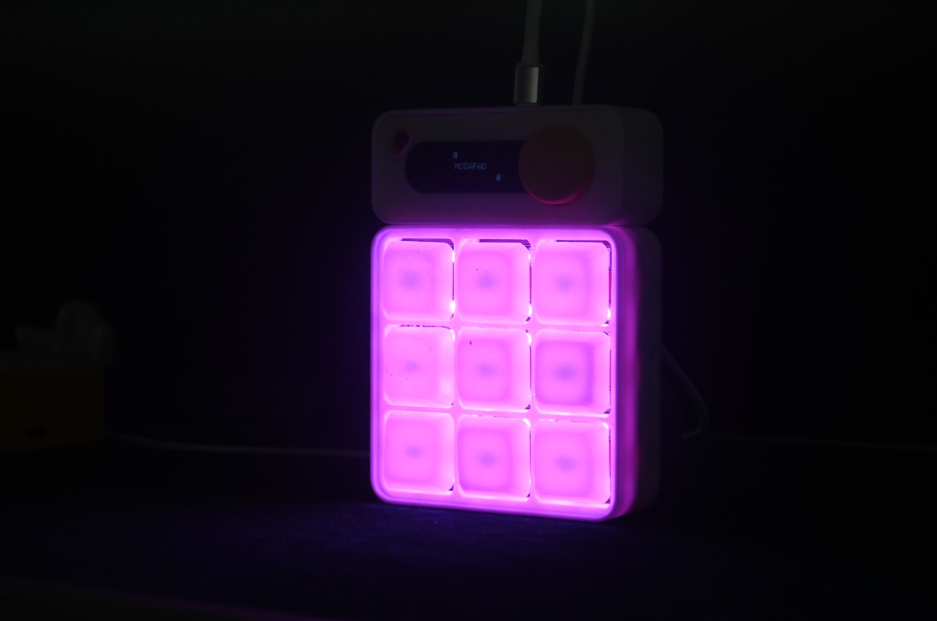
void startup() {
// turn on Modules
//Play Melady
startup_tone();
//Lightup: Running LEDs Purple
// Display OLED: Startup screen
display.setTextSize(2);
display.setTextColor(SH110X_WHITE);
display.setCursor(0, 0);
display.print("@");
display.setCursor(5, 25);
display.print("MOGAPAD");
display.setCursor(115, 50);
display.print("@");
display.display();
gameStatus = true;
sendCMD(48 + 30);
delay(3000);
sendCMD(48 + 20);
}
// XOX Algorithums
//possibilities
int check(char a[16], int n) {
// for printing the array
// for(int i=0; i<= 8;i++)
// {
// Serial.print(a[i]);
// }
// Serial.println("");
if (a[0] == 'X' && a[1] == 'X' && a[2] == 'X')
return 1;
if (a[0] == '0' && a[1] == '0' && a[2] == '0')
return 2;
if (a[0] == 'X' && a[3] == 'X' && a[6] == 'X')
return 1;
if (a[0] == '0' && a[3] == '0' && a[6] == '0')
return 2;
if (a[0] == 'X' && a[4] == 'X' && a[8] == 'X')
return 1;
if (a[0] == '0' && a[4] == '0' && a[8] == '0')
return 2;
if (a[3] == 'X' && a[4] == 'X' && a[5] == 'X')
return 1;
if (a[3] == '0' && a[4] == '0' && a[5] == '0')
return 2;
if (a[6] == 'X' && a[7] == 'X' && a[8] == 'X')
return 1;
if (a[6] == '0' && a[7] == '0' && a[8] == '0')
return 2;
if (a[1] == 'X' && a[4] == 'X' && a[7] == 'X')
return 1;
if (a[1] == '0' && a[4] == '0' && a[7] == '0')
return 2;
if (a[2] == 'X' && a[5] == 'X' && a[8] == 'X')
return 1;
if (a[2] == '0' && a[5] == '0' && a[8] == '0')
return 2;
if (a[2] == 'X' && a[4] == 'X' && a[6] == 'X')
return 1;
if (a[2] == '0' && a[4] == '0' && a[6] == '0')
return 2;
else
return 0;
}
void gameReset(){
sendCMD(48 + 20);
e = 0;
for(int i=0; i<= 8;i++)
{
a[i] = i+48;
}
for(int i=0; i<= 8;i++)
{
Serial.print(a[i]);
}
Serial.println("");
}
// Communication
void sendCMD(int cmd) {
// Write data to slave
Wire.beginTransmission(8); // address of slave
Wire.write(cmd);
Wire.endTransmission();
Serial.print("Sent: ");
Serial.println(cmd);
delay(100);
}
void getStatus() {
// Now request 1 byte from slave
Wire.requestFrom(8, 1);
if (Wire.available()) {
byte received = Wire.read();
Serial.print("Received from slave: ");
KeyData = received - 48;
Serial.println(KeyData);
keyPressed = true;
}
}
//Tones
void startup_tone() {
tone(BUZZER_PIN, 262, 500); // C4
delay(200);
tone(BUZZER_PIN, 294, 500); // D4
delay(200);
tone(BUZZER_PIN, 330, 500); // E4
delay(200);
tone(BUZZER_PIN, 349, 500); // F4
delay(200);
noTone(BUZZER_PIN);
delay(500);
}
void shutdown_tone() {
noTone(BUZZER_PIN);
delay(500);
tone(BUZZER_PIN, 349, 500); // F4
delay(200);
tone(BUZZER_PIN, 330, 500); // E4
delay(200);
tone(BUZZER_PIN, 294, 500); // D4
delay(200);
tone(BUZZER_PIN, 262, 500); // C4
delay(200);
}
void gamefail_tone() {
tone(BUZZER_PIN, 500, 200);
delay(200);
tone(BUZZER_PIN, 500, 200);
delay(200);
tone(BUZZER_PIN, 500, 200);
delay(200);
tone(BUZZER_PIN, 800, 150);
delay(150);
tone(BUZZER_PIN, 500, 500);
delay(500);
tone(BUZZER_PIN, 600, 1000);
delay(10000);
}
  //Code for MogApad Node Module with ATTINY 1614

#include <Keypad.h>
#include <Wire.h>
#include <Adafruit_NeoPixel.h>
#ifdef __AVR__
#include <avr/power.h>  // Required for 16 MHz Adafruit Trinket
#endif


#define INT_PULLS 7
// On a Trinket or Gemma we suggest changing this to 1:
#define LED_PIN 10

// How many NeoPixels are attached to the Arduino?
#define LED_COUNT 36


bool ledUpdate = false;
int ledData = 0;
volatile byte receivedData = 0;

volatile byte dataToSend = 0;  // Example data to send


Adafruit_NeoPixel strip(LED_COUNT, LED_PIN, NEO_GRB + NEO_KHZ800);

int getLED[9][4] = {

  { 0, 1, 11, 10 },
  { 2, 3, 9, 8 },
  { 4, 5, 7, 6 },
  { 12, 13, 23, 22 },
  { 14, 15, 21, 20 },
  { 16, 17, 19, 18 },
  { 24, 25, 35, 34 },
  { 26, 27, 33, 32 },
  { 28, 29, 31, 30 }


};

bool ledStatus[36];


const byte ROWS = 3;  //four rows
const byte COLS = 3;  //four columns
//define the cymbols on the buttons of the keypads
char hexaKeys[ROWS][COLS] = {
  { '2', '5', '8' },
  { '1', '4', '7' },
  { '0', '3', '6' }


};

byte rowPins[ROWS] = { 2, 4, 5 };  //connect to the row pinouts of the keypad
byte colPins[COLS] = { 0, 3, 1 };  //connect to the column pinouts of the keypad

//initialize an instance of class NewKeypad
Keypad customKeypad = Keypad(makeKeymap(hexaKeys), rowPins, colPins, ROWS, COLS);

void setup() {
  Wire.swap(1);
  Wire.begin(8);                 // join i2c bus with address #8
  Wire.onReceive(receiveEvent);  // register receive event
  Wire.onRequest(requestEvent);  // register request event


  pinMode(INT_PULLS, OUTPUT);
  digitalWrite(INT_PULLS, HIGH);
  // LED
  strip.begin();            // INITIALIZE NeoPixel strip object (REQUIRED)
  strip.show();             // Turn OFF all pixels ASAP
  strip.setBrightness(50);  // Set BRIGHTNESS to about 1/5 max = 255
  strip.clear();
}

void loop() {
  // mySerial.println("Hello");
  // delay(500);
  int key = getkey();
  if (ledUpdate) {
    int ledPos = ledData % 10;
    int coloToggle = (ledData / 10) % 10;
    if (coloToggle) {

    } else {
    }

    switch (coloToggle) {
      case 0:
        showkey(ledPos, strip.Color(0, 0, 127));
        break;
      case 1:
        showkey(ledPos, strip.Color(127, 0, 0));
        break;
      case 2:
          clearLEDS();
        break;
      case 3:
            breathingEffect(128, 0, 128, 5); // Blue color breathing
        break;
    }

    ledUpdate = false;
  }

  //  theaterChase(strip.Color(127, 127, 127), 50);
}
int getkey() {
  char customKey = customKeypad.getKey();

  if (customKey) {
    digitalWrite(INT_PULLS, LOW);
    delay(50);
    digitalWrite(INT_PULLS, HIGH);
    // mySerial.println(customKey);
    dataToSend = customKey;
    return (((String)customKey).toInt());
  }
  return (-1);
}


void requestEvent() {
  Wire.write(dataToSend);
  Serial.print("Sent: ");
  Serial.println(dataToSend);
}

void receiveEvent(int howMany) {
  // while (1 < Wire.available()) {
  //   char c = Wire.read();
  //   Serial.print(c);
  // }
  int x = Wire.read();
  receivedData = x;

  ledData = x - 48;
  ledUpdate = true;
  // Serial.print("Received: ");
  // Serial.println(x);
}

void showkey(int key, uint32_t color) {
  for (int i = 0; i < 4; i++) {
    strip.setPixelColor(getLED[key][i], color);
  }
  strip.show();
}

void clearLEDS() {
  strip.clear(); // Set all pixel colors to 'off'
  strip.show();
}
// void theaterChase(uint32_t color, int wait) {
//   for (int a = 0; a < 2; a++) {    // Repeat 10 times...
//     for (int b = 0; b < 3; b++) {  //  'b' counts from 0 to 2...
//       strip.clear();               //   Set all pixels in RAM to 0 (off)
//       // 'c' counts up from 'b' to end of strip in steps of 3...
//       for (int c = b; c < strip.numPixels(); c += 3) {
//         strip.setPixelColor(c, color);  // Set pixel 'c' to value 'color'
//       }
//       strip.show();  // Update strip with new contents
//       delay(wait);   // Pause for a moment
//     }
//   }
// }


// Breathing function
void breathingEffect(uint8_t red, uint8_t green, uint8_t blue, int delayTime) {
  // Fade in
  for (int brightness = 0; brightness <= 255; brightness++) {
    setAll(red, green, blue, brightness);
    delay(delayTime);
  }
  // Fade out
  for (int brightness = 255; brightness >= 0; brightness--) {
    setAll(red, green, blue, brightness);
    delay(delayTime);
  }
}

// Helper function to set all pixels
void setAll(uint8_t red, uint8_t green, uint8_t blue, uint8_t brightness) {
  uint32_t color = strip.Color(
    (red * brightness) / 255,
    (green * brightness) / 255,
    (blue * brightness) / 255
  );

  for (int i = 0; i < LED_COUNT; i++) {
    strip.setPixelColor(i, color);
  }
  strip.show();
}