9.Input Devices
This week's brief:
Group assignment:
GROUP ASSIGNMENT
You can view our group assignment here!
INDIVIDUAL ASSIGNMENT
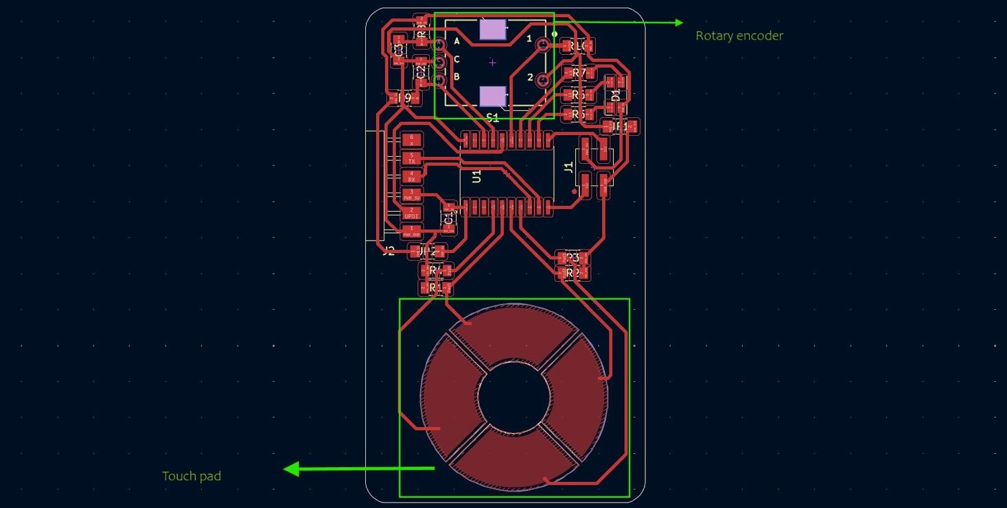
So i thought about adding a possible feature to my project that can incorporate a sensor. I had intially thought of making a capacitive scrollpad to help navigate the score/difficulty setting of the game. After dicussing this with my instructor, i was given an option of using an rotary encoder to do the same function. So i thought of learning more about these two sensors by comparing them and then see which would be better suited for my project..
Rotary Encoder and Capacitive sensor- comparative study
ROTARY ENCODER
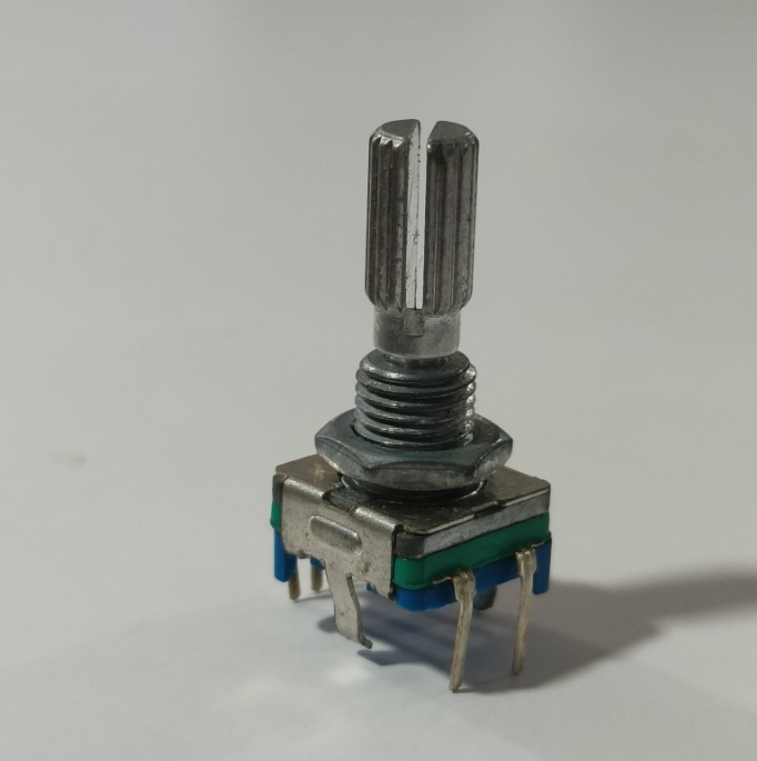
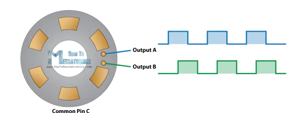
Rotary encoder is a a type of position sensor that translates the rotational movement of a shaft into an electrical signal, providing feedback about position, speed, and direction.
It is- 1. Highly reliable and accurate
2. Low-cost feedback
3. High resolution
4. Integrated electronics
5. Fuses optical and digital technology
6. Can be incorporated into existing applications
7. Compact size
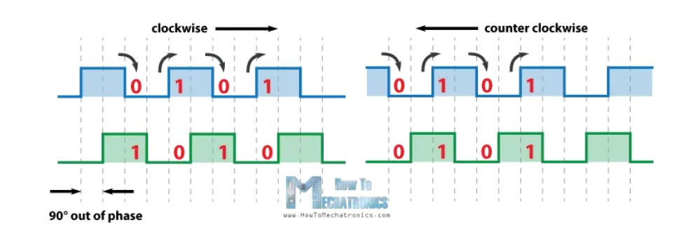
 So if we count the steps each time the signal changes, from High to Low or from Low to High, we can notice at that
time the two output signals have opposite values. Vice versa, if the encoder is rotating counter clockwise, the
output signals have equal values. So considering this, we can easily program our controller to read
the encoder position and the rotation direction.
So if we count the steps each time the signal changes, from High to Low or from Low to High, we can notice at that
time the two output signals have opposite values. Vice versa, if the encoder is rotating counter clockwise, the
output signals have equal values. So considering this, we can easily program our controller to read
the encoder position and the rotation direction.
CAPACITIVE SENSING
Capacitive sensors detect objects by measuring changes in capacitance, which occurs when an object enters the sensor's electrostatic field, without needing physical contact
Principle
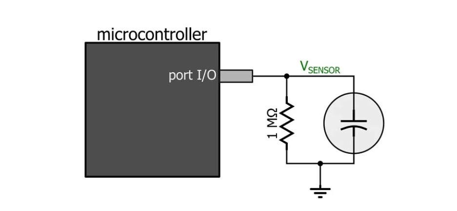
A basic capacitor takes time to fully charge when subjected to a specific voltage and can discharge when the
voltage source is removed and the capacitor is connected to a sink. The duration of this charge and discharge
process remains relatively constant when the circuit parameters are unchanged.
However, this duration varies when the circuit's capacitance changes. This principle forms the basis of capacitive
touch screens.
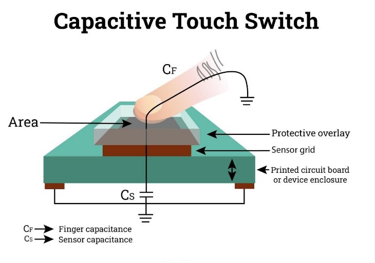
When a human finger touches the screen, it introduces an additional capacitor into the circuit, increasing the
overall capacitance. Human skin acts as a dielectric material, altering the circuit's charging and discharging
times.
This change in charge-discharge duration is used to detect user interactions.
A dedicated microcontroller typically manages this process, charging the capacitive screen and monitoring changes
in the circuit's charge-discharge times.
When deviations from the norm are detected, the microcontroller signals the main controller to register the user's
touch.
(*To have a deeper understanding about how this works, you can refer to the materials I also took notes from which could be found at the end of this page*)
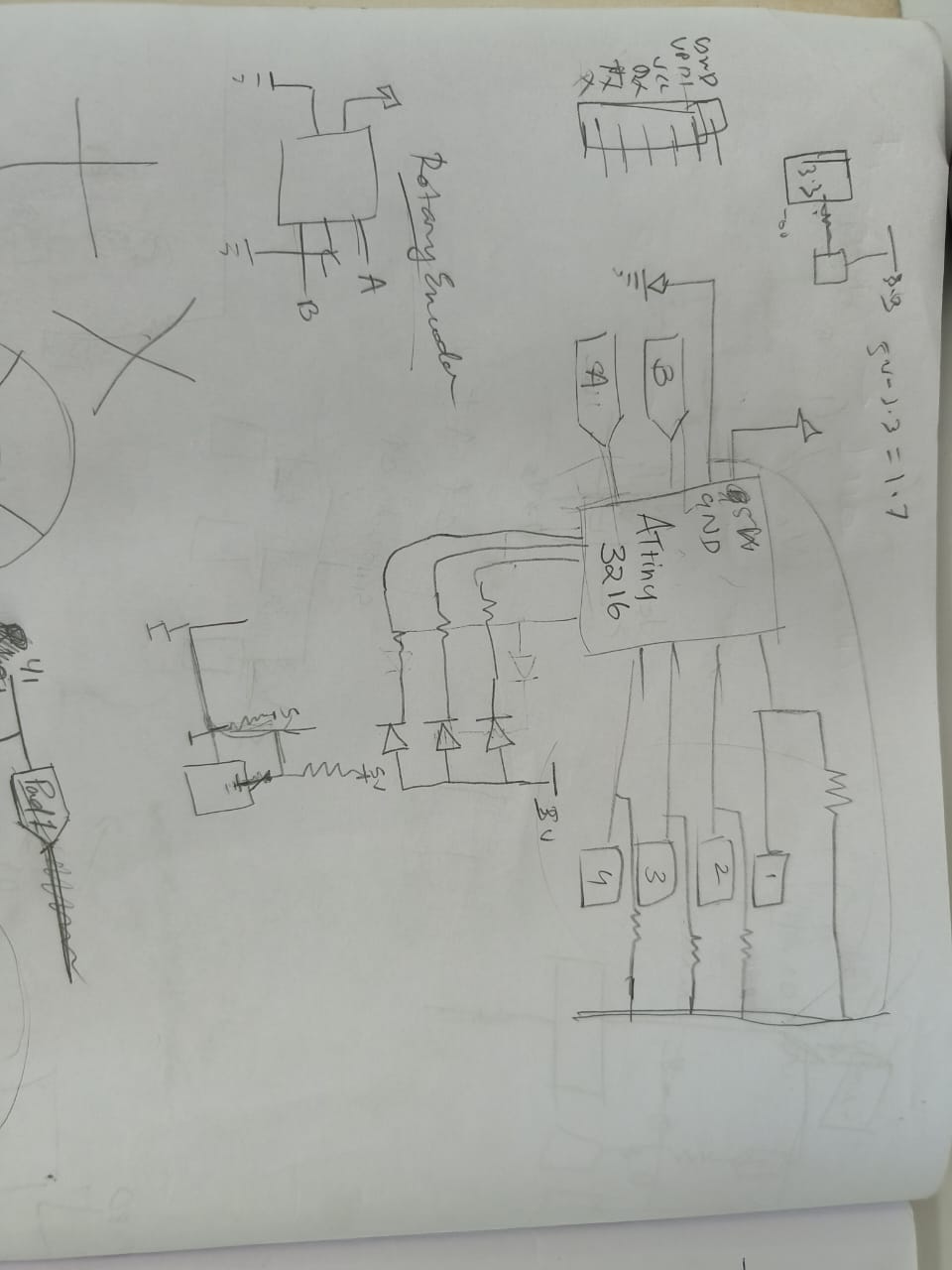
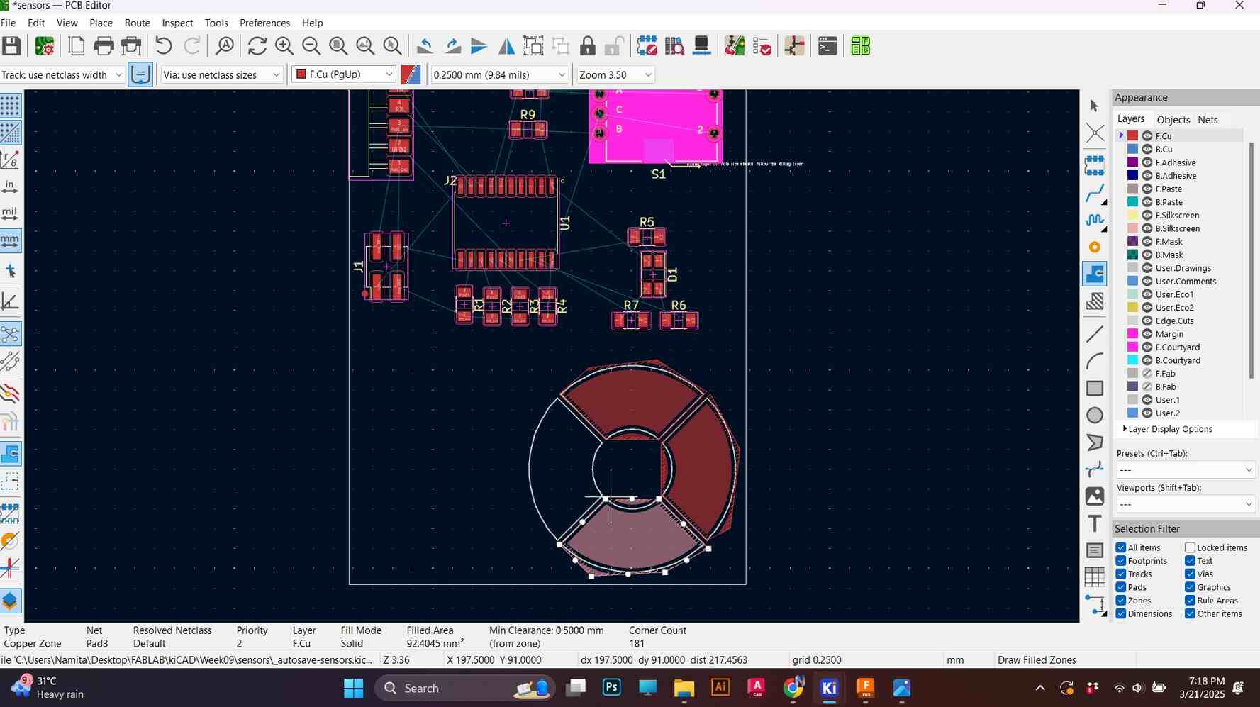
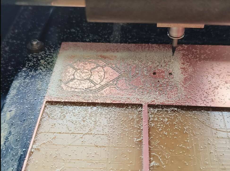
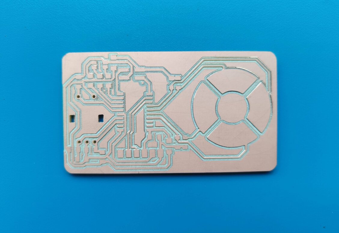
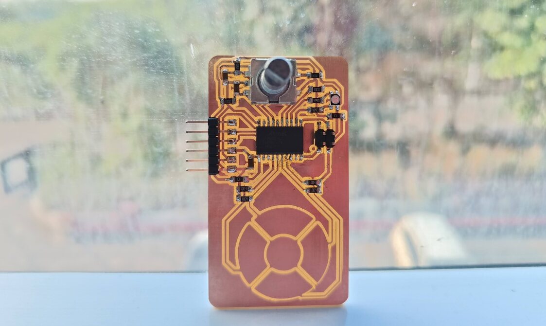
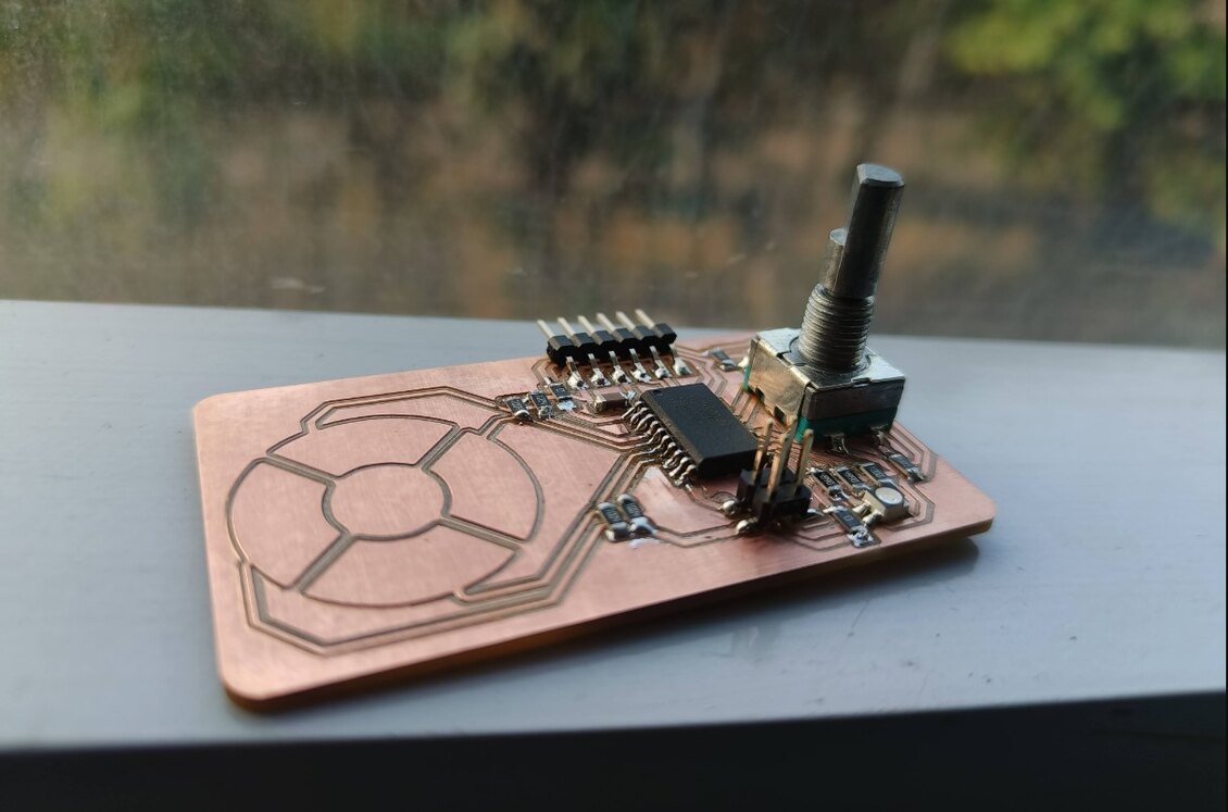
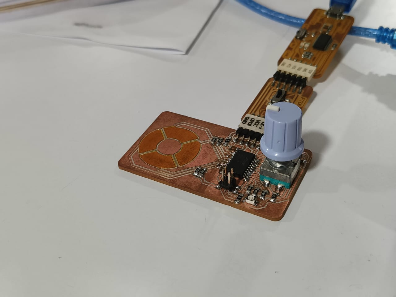
Making the circuit
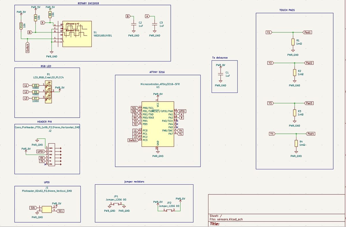
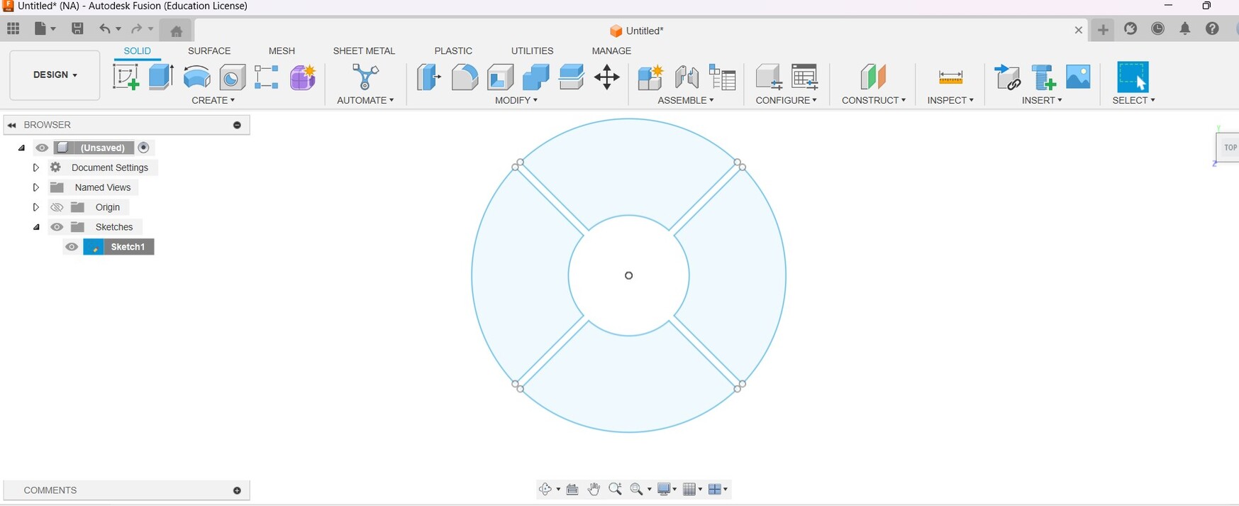
After placing it properly, we have to use copper fill function to make the scroll area pads.We need to draw out the pathway where the pads should be and close the path. Click on 'B' to fill in the shape path. i did the same for the other 3 pads.
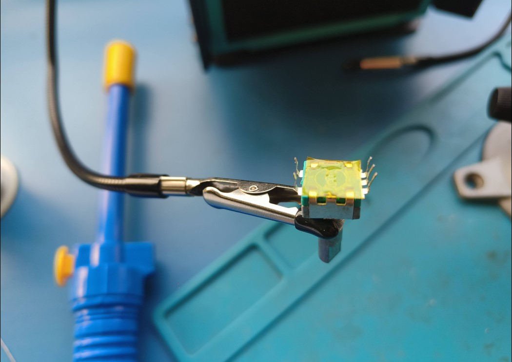
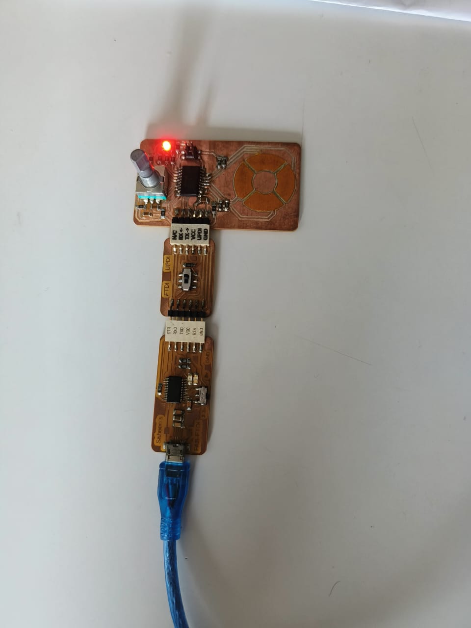
Programming
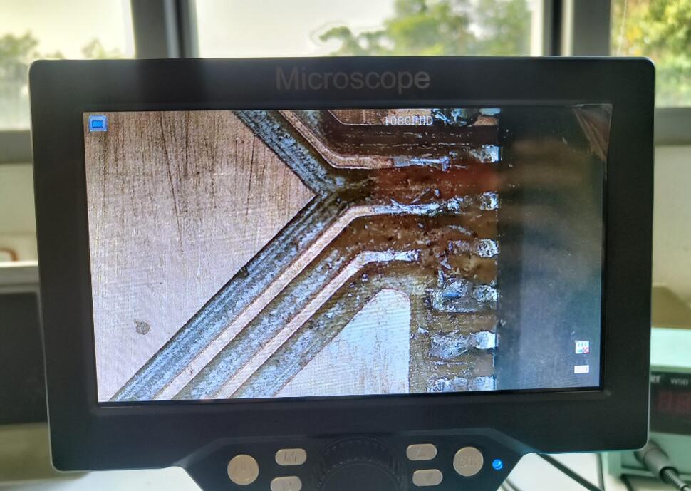
I had to do some research to understand the type of code that i could use according to my pcb and since i have two sensors i had to see how i can combine the codes into a single file too.I connected my PCB to a programmer to connect it to my laptop and ran a simple blink test to check if its working. I referred to Revishanker's documentation to setup the board in arduino IDE.
Rotary Encoder
I referred to Sayanth's documentation to understand the code for the endoder and ran it to check if im getting an output.Setup Function for encoder:
  #define ENCODER_PIN_A 14  // Pin connected to encoder A output
  #define ENCODER_PIN_B 15  // Pin connected to encoder B output
  #define ENCODER_BUTTON_PIN 13
  #define LED_RED_PIN 12     // the number of the LED pin


  volatile int encoderCount = 0;


  bool ledState = false;         // the current state of the LED
  int buttonState;               // the current reading from the input pin
  bool lastButtonState = false;  // the previous reading from the input pin

  // the following variables are long because the time, measured in milliseconds,
  // will quickly become a bigger number than can be stored in an int.
  unsigned long lastDebounceTime = 0;  // the last time the output pin was toggled
  unsigned long debounceDelay = 50;    // the debounce time; increase if the output flickers


  void setup() {
    pinMode(ENCODER_BUTTON_PIN, INPUT_PULLUP);
    pinMode(LED_RED_PIN, OUTPUT);

    pinMode(ENCODER_PIN_A, INPUT);
    pinMode(ENCODER_PIN_B, INPUT);
    attachInterrupt(digitalPinToInterrupt(ENCODER_PIN_A), encoderISR, CHANGE);


    Serial.begin(9600);
  }

  void loop() {
      // Print the encoder count
      Serial.print(" Encoder Count: ");
    Serial.println(encoderCount);
    delay(100);  // Update every second


    // read the state of the switch into a local variable:
    int reading = digitalRead(ENCODER_BUTTON_PIN);

    // check to see if you just pressed the button
    // (i.e., the input went from LOW to HIGH), and you've waited long enough
    // since the last press to ignore any noise:

    // If the switch changed, due to noise or pressing:
    if (reading != lastButtonState) {
      // reset the debouncing timer
      lastDebounceTime = millis();
    }

    if ((millis() - lastDebounceTime) > debounceDelay) {
      // whatever the reading is at, it's been there for longer than the debounce
      // delay, so take it as the actual current state:

      // if the button state has changed:
      if (reading != buttonState) {
        buttonState = reading;

        // only toggle the LED if the new button state is HIGH
        if (buttonState == HIGH) {

          encoderCount = 0;
          ledState = !ledState;
        }
      }
    }


    // set the LED:
    digitalWrite(LED_RED_PIN, ledState);

    // save the reading. Next time through the loop, it'll be the lastButtonState:
    lastButtonState = reading;
  }

  void encoderISR() {
    // Read the state of pin B
    if (digitalRead(ENCODER_PIN_A) == digitalRead(ENCODER_PIN_B)) {
      encoderCount++;
    } else {
      encoderCount--;
    }
    //   Serial.print(" Encoder Count: ");
    // Serial.println(encoderCount);
  }
The real time readings i obtained looked like this:
Capacitive Touch
I refered to Neil's hello.TLE493D.t412 board and code to find the sample values entered to start off my code. I modified the code to fit my board.#define sense_pin PIN_PA1 // sense pin
#define settle 100 // settling time
#define samples 1000 // number of samples to accumulate
void setup() {
Serial.begin(115200); // start serial
analogSampleDuration(10); // set ADC sampling rate
analogReadResolution(10); // set ADC resolution
}
void loop() {
int32_t count;
count = 0;
noInterrupts(); // disable interrupts while measuring
for (int i = 0; i < samples; ++i) {
pinMode(sense_pin,OUTPUT); // set sense pin to output
digitalWriteFast(sense_pin,HIGH); // charge up
delayMicroseconds(settle); //settle
pinMode(sense_pin,INPUT); // set sense pin to input
count += analogRead(sense_pin); // read discharge
}
interrupts(); // enable interrupts after measuring
Serial.println(count); // send count
Serial.flush(); // finish communicating before measuring
}
i added the code for the second pad.
Programming for scroll wheel
After i figured out how to connect and read values of the two pads, I had make a code to make a value increase or decrease according to the direction in which the finger moves. If the finger moves clockwise a value should be incremented at the crossover between the pads. Similarly the value should see decrement when the finger moves anticlockwise.I had to seek out the help of my instructor Saheen and our lab's in house developer Midhulaj to discuss and figure out how to program this. After some brainstorming we found that we could use an array to read and check the direction. The logic is as follows:
- We need to initialise an array 'd' with 4 values as 0 (since i have 4 pad readings to check). i also initialised a variable level set to 0 to show the increase or decrease to indicate direction . We need to check all fur pad readings using the same criteria's , so for the ease of understanding i will explain how the value from pad 1 to pad 2 was read.
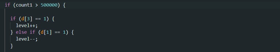
- We use the sample variable 'count1' to set a threshold value for pad1 to check whether a touch was registered on the pad. From the serial monitor we found out that the range of values went from around 420000 to 500000+ when the touch was sensed. So an if statement is given so that whenever the value of 'count1' is greater than the threshold value 500000 we proceed to enter the if() to check one more requirement for understanding the direction
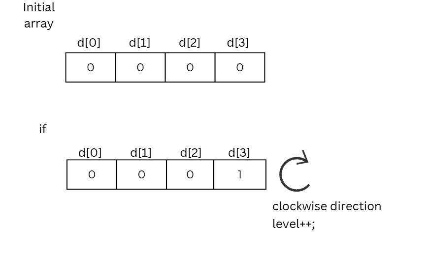
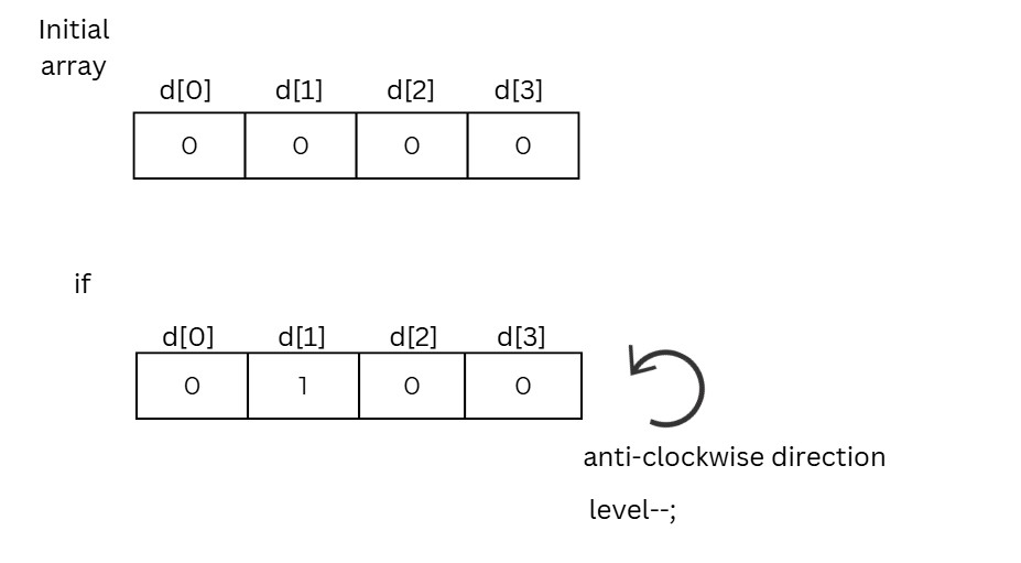
- Here is where we bring in the array. So by our logic when the program enters the if statement , if the previous array value is found to be 1 then the direction is clockwise and conversely if the next array value is found to be 1 the the direction becomes clockwise.
- So when checking for pad1 d[3] should be 1 if the rotation is clockwise and level will be incremented . Else if the next array, d [1] is 1 then it is anticlockwise and level is decreased.
- Before we go out of the first if() we have to assign d[0] as 1 since the touch was registered there and also reset the rest of the array values as 0 , so that the same logic can be applied each time.
- We just need to repeat the same code for the rest of the 3 pad readings. at the end we need to ask to print the value of "level" along with the samples.
      #define sense_pin1 PIN_PA7  // sense pin
      #define sense_pin2 PIN_PB5
      #define sense_pin3 PIN_PB4
      #define sense_pin4 PIN_PA6
      #define settle 100    // settling time
      #define samples 1000  // number of samples to accumulate
      int d[4] = { 0, 0, 0, 0 }; // array for cheching the directional change
      int level = 0;     // value to be increased or decreased according to the direction

      void setup() {
        Serial.begin(115200);      // start serial
        analogSampleDuration(10);  // set ADC sampling rate
        analogReadResolution(10);  // set ADC resolution
      }

      void loop() {
        dial();
      }


      void dial() {
        int32_t count1; // for checking the threshhold value
        int32_t count2;
        int32_t count3;
        int32_t count4;


        count1 = 0;
        count2 = 0;
        count3 = 0;
        count4 = 0;
        noInterrupts();  // disable interrupts while measuring

        for (int i = 0; i < samples; ++i) {

          pinMode(sense_pin2, OUTPUT);         // set sense pin2 to output
          digitalWriteFast(sense_pin2, HIGH);  // charge up

          pinMode(sense_pin1, OUTPUT);         // set sense pin1 to output
          digitalWriteFast(sense_pin1, HIGH);  // charge up

          pinMode(sense_pin3, OUTPUT);         // set sense pin3 to output
          digitalWriteFast(sense_pin3, HIGH);  // charge up

          pinMode(sense_pin4, OUTPUT);         // set sense pin4 to output
          digitalWriteFast(sense_pin4, HIGH);  // charge up

          delayMicroseconds(settle);  //settle

          pinMode(sense_pin1, INPUT);        // set sense pin1 to input
          count1 += analogRead(sense_pin1);  // read discharge
          pinMode(sense_pin2, INPUT);        // set sense pin2 to input
          count2 += analogRead(sense_pin2);  // read discharge

          pinMode(sense_pin3, INPUT);        // set sense pin3 to input
          count3 += analogRead(sense_pin3);  // read discharge

          pinMode(sense_pin4, INPUT);        // set sense pin4 to input
          count4 += analogRead(sense_pin4);  // read discharge
        }
        interrupts();          // enable interrupts after measuring
        Serial.print(count1);  // send count

        Serial.print(" ");
        Serial.print(count2);

        Serial.print(" ");
        Serial.print(count3);

        Serial.print(" ");
        Serial.println(count4);


        if (count1 > 500000) { //for pad1

          if (d[3] == 1) {
            level++;
          } else if (d[1] == 1) {
            level--;
          }

          d[0] = 1;
          d[1] = 0;
          d[2] = 0;
          d[3] = 0;
        }

        if (count2 > 300000) { // for pad2
          if (d[0] == 1) {
            level++;
          } else if (d[2] == 1) {
            level--;
          }

          d[0] = 0;
          d[1] = 1;
          d[2] = 0;
          d[3] = 0;
        }


        if (count3 > 300000) {  //for pad3

          if (d[1] == 1) {
            level++;
          } else if (d[3] == 1) {
            level--;
          }

          d[0] = 0;
          d[1] = 0;
          d[2] = 1;
          d[3] = 0;
        }

        if (count4 > 450000) {  //for pad4

          if (d[2] == 1) {
            level++;
          } else if (d[0] == 1) {
            level--;
          }

          d[0] = 0;
          d[1] = 0;
          d[2] = 0;
          d[3] = 1;
        }

        Serial.println(level);
        Serial.flush();  // finish communicating before measuring
      }
The real time readings i obtained looked like this:
I would like to further write the codes for changing the brightness levels as well as changing the colour of the RGB led using the rotary encoder and the scrollpad
-->Download files
References
About rotary Encoder.
About Capacitive sensing