This week's assignment was to test input devices using different development boards. I used a rotary encoder as an input device to explore its functionality and integration with my project.
Introduction to Rotary Encoders
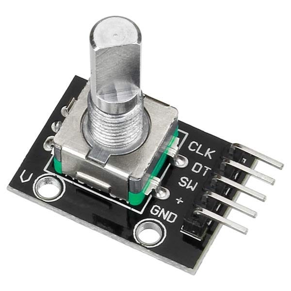
A rotary encoder is an electromechanical device that converts the angular position or motion of a shaft or axle to an analog or digital code. Rotary encoders are used in a wide range of applications that require precise measurement of rotation, such as in industrial controls, robotics, and consumer electronics.
Types of Rotary Encoders
There are two main types of rotary encoders:
Absolute Encoders: These provide a unique code for each shaft position. They are used where it is necessary to know the exact position of the shaft, even after a power cycle.
Incremental Encoders: These provide relative position changes. They are simpler and more common for general purposes. They count pulses generated as the shaft rotates and are often used where the absolute position is not required.
How Rotary Encoders Work
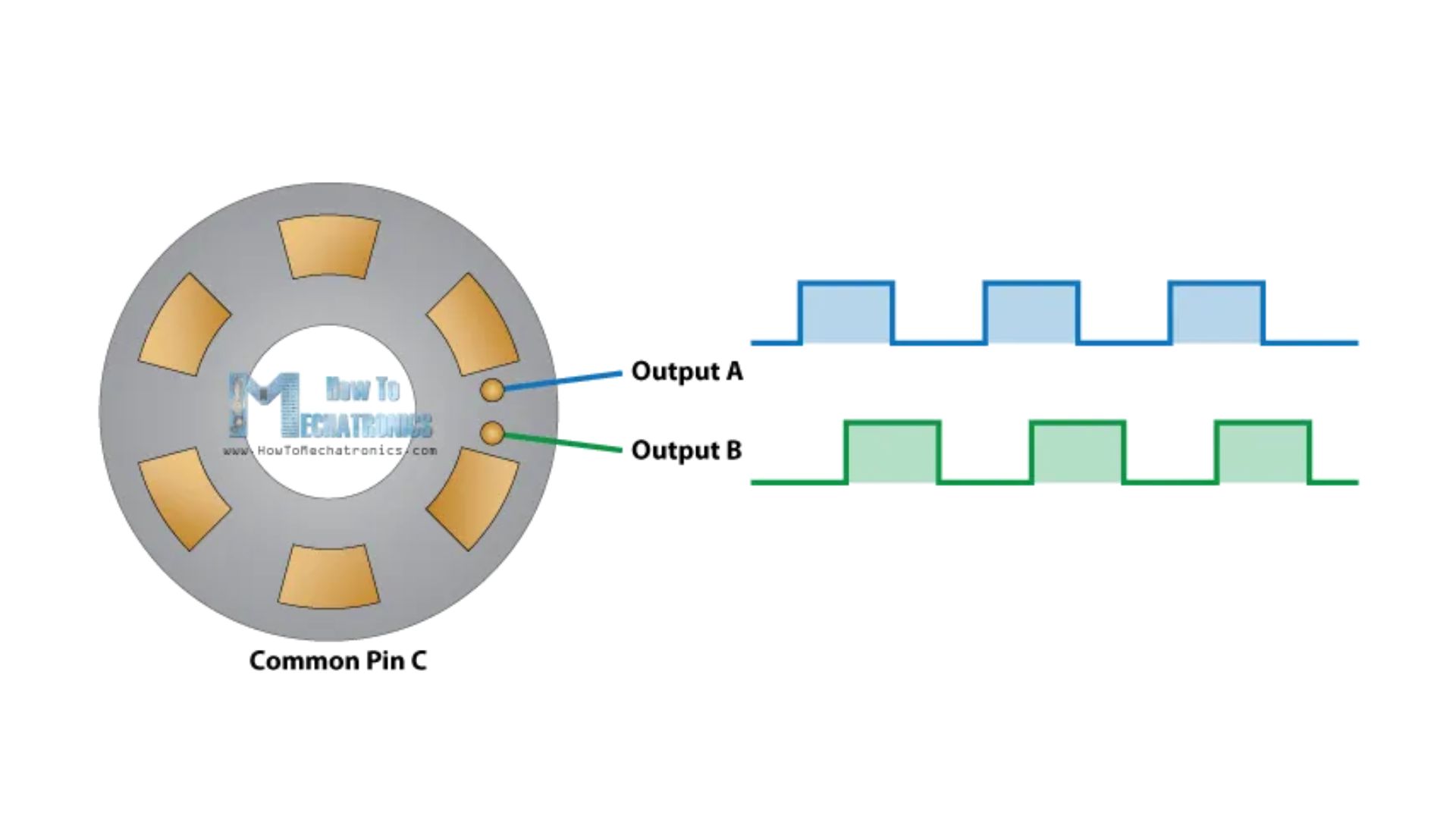
A rotary encoder consists of a disk, usually made of glass or plastic, with alternating transparent and opaque segments. As the disk rotates, it interrupts a light beam, generating pulses that are counted by the controlling device. The number of pulses per rotation indicates the resolution of the encoder.
image courtsy howtomechatronics.com
Applications of Rotary Encoders
Rotary encoders are versatile and used in various applications, including:
Volume Control: In audio equipment, rotary encoders can be used for precise volume adjustments.
Positioning Systems: In CNC machines and robotic arms, they provide feedback on the position of moving parts.
User Interfaces: In control panels and digital interfaces, they serve as user input devices for menu navigation and selection.
PCB Design with ATtiny1614 Microcontroller
Components Used:
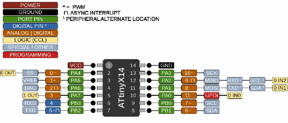
ATtiny1614 Microcontroller: An 8-bit microcontroller with 16 KB Flash memory, commonly used in embedded systems.
Decoupling Capacitors: Used to filter noise and stabilize voltage supply to the microcontroller.
Onboard LED: Visual indicator for status monitoring and debugging.
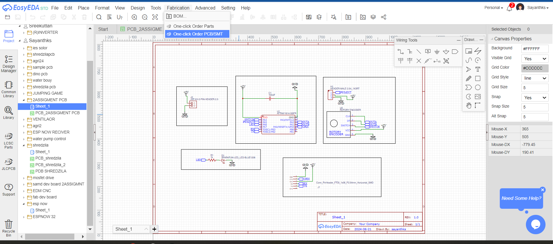
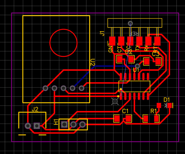
schematic
i used EASYEDA for drawing the pcb and started of with the schemitcs
then i used EASYEDA for drawing the pcb and started of with the pcb and exporeted the gerber
Integrating Rotary Encoder into PCB Design
Wiring the Rotary Encoder to the PCB
Integrating a rotary encoder with the ATtiny1614 microcontroller involves connecting the encoder's pins to the microcontroller's GPIO pins, specifically using interrupt-capable pins for optimal performance. Here’s how to proceed:
Identify Rotary Encoder Pins:
Typical rotary encoders have three pins: A, B, and C (or SW).
A and B pins: Used to detect the rotational movement and direction changes.
C (SW) pin: This is the switch pin, used for additional functionalities like resetting or confirming selections.
Connect Rotary Encoder Pins to ATtiny1614:
Encoder Pins A and B: Connect these to any two GPIO pins9 and 8 on the ATtiny1614 for reading rotational movement.
Encoder Pin C (SW): Optionally, connect this to another GPIO pin 0
Using Interrupts for Rotary Encoder:
Configure the ATtiny1614 microcontroller to use interrupts for pins A and B.
Interrupts allow the microcontroller to respond immediately to changes in the encoder's state (rotational movement).
By following these steps in EasyEDA, you can effectively design and integrate a rotary encoder into your PCB with the ATtiny1614 microcontroller. This approach ensures precise control and input detection directly from the encoder, enhancing the functionality of your embedded system project.
please refer the documentation on week 9 to get more information on designing pcb with easy eda
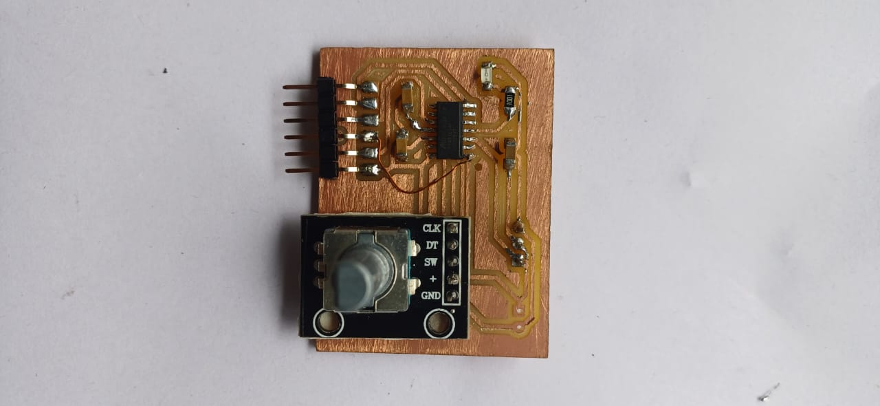
then i used fab modes to send the files to the milling machine and milled the pcb and assembled it
please refer the documentation on week 6 to get more information on USING FABMODS AND PCB MILLING
Rotary Encoder Code
The following code demonstrates how to interface with a rotary encoder using an Arduino. The code reads the position of the rotary encoder and prints the position to the serial monitor.
        #define ENCODER_PIN_A 9  // Pin connected to encoder A output
        #define ENCODER_PIN_B 8  // Pin connected to encoder B output
        #define ENCODER_BUTTON_PIN 0
        #define LED_PIN 2     // the number of the LED pin


        volatile int encoderCount = 0;


        bool ledState = false;         // the current state of the LED
        int buttonState;               // the current reading from the input pin
        bool lastButtonState = false;  // the previous reading from the input pin

        // the following variables are long because the time, measured in milliseconds,
        // will quickly become a bigger number than can be stored in an int.
        unsigned long lastDebounceTime = 0;  // the last time the output pin was toggled
        unsigned long debounceDelay = 50;    // the debounce time; increase if the output flickers


        void setup() {
          pinMode(ENCODER_BUTTON_PIN, INPUT_PULLUP);
          pinMode(LED_PIN, OUTPUT);

          pinMode(ENCODER_PIN_A, INPUT);
          pinMode(ENCODER_PIN_B, INPUT);
          attachInterrupt(digitalPinToInterrupt(ENCODER_PIN_A), encoderISR, CHANGE);


          Serial.begin(9600);
        }

        void loop() {
            // Print the encoder count
            Serial.print("Encoder Count: ");
          Serial.println(encoderCount);
          delay(100);  // Update every second


          // read the state of the switch into a local variable:
          int reading = digitalRead(ENCODER_BUTTON_PIN);

          // check to see if you just pressed the button
          // (i.e., the input went from LOW to HIGH), and you've waited long enough
          // since the last press to ignore any noise:

          // If the switch changed, due to noise or pressing:
          if (reading != lastButtonState) {
            // reset the debouncing timer
            lastDebounceTime = millis();
          }

          if ((millis() - lastDebounceTime) > debounceDelay) {
            // whatever the reading is at, it's been there for longer than the debounce
            // delay, so take it as the actual current state:

            // if the button state has changed:
            if (reading != buttonState) {
              buttonState = reading;

              // only toggle the LED if the new button state is HIGH
              if (buttonState == HIGH) {

                encoderCount = 0;
                ledState = !ledState;
              }
            }
          }


          // set the LED:
          digitalWrite(LED_PIN, ledState);

          // save the reading. Next time through the loop, it'll be the lastButtonState:
          lastButtonState = reading;
        }

        void encoderISR() {
          // Read the state of pin B
          if (digitalRead(ENCODER_PIN_A) == digitalRead(ENCODER_PIN_B)) {
            encoderCount++;
          } else {
            encoderCount--;
          }
          //   Serial.print("Encoder Count: ");
          // Serial.println(encoderCount);
        }
Explanation of the Code
This sketch handles the reading of a rotary encoder's output to track its rotation count and the reading of a button to reset the encoder count and toggle an LED. The sketch includes debounce logic to ensure reliable button presses.
Pin Definitions
ENCODER_PIN_A: Pin connected to encoder A output (Pin 9).
ENCODER_PIN_B: Pin connected to encoder B output (Pin 8).
ENCODER_BUTTON_PIN: Pin connected to the encoder button (Pin 0).
LED_PIN: Pin connected to an LED (Pin 2).
Global Variables
volatile int encoderCount: Stores the encoder count and must be volatile since it is modified within an interrupt service routine (ISR).
bool ledState: Tracks the current state of the LED (initially false).
int buttonState: Stores the current reading from the button pin.
bool lastButtonState: Stores the previous reading from the button pin (initially false).
unsigned long lastDebounceTime: Tracks the last time the button state was toggled for debounce logic (initially 0).
unsigned long debounceDelay: The debounce time in milliseconds to ignore any noise from the button press (set to 50 ms).
Setup Function
In the setup function:
The encoder button pin is set as an input with an internal pull-up resistor.
The LED pin is set as an output.
The encoder pins A and B are set as inputs.
An interrupt is attached to the encoder pin A to trigger on any change, which calls the encoderISR function.
Serial communication is initialized at a baud rate of 9600.
Loop Function
In the loop function:
The encoder count is printed to the serial monitor every 100 milliseconds.
The state of the button is read into a local variable (reading).
If the button state has changed, the debounce timer is reset.
If enough time has passed since the last state change (debounce period), the button state is checked:
If the button state has changed, update the buttonState variable.
If the button is pressed (state is HIGH), reset the encoder count to 0 and toggle the LED state.
The LED state is updated based on the ledState variable.
The current button reading is saved as lastButtonState for the next iteration.
Encoder Interrupt Service Routine (ISR)
The encoderISR function:
Reads the state of the encoder pin B and compares it with the state of encoder pin A to determine the rotation direction.
If both pins have the same state, the encoder count is incremented, indicating rotation in one direction.
If the pins have different states, the encoder count is decremented, indicating rotation in the opposite direction.
 see the group assingment here