Week 15. System Integration
This week's brief:
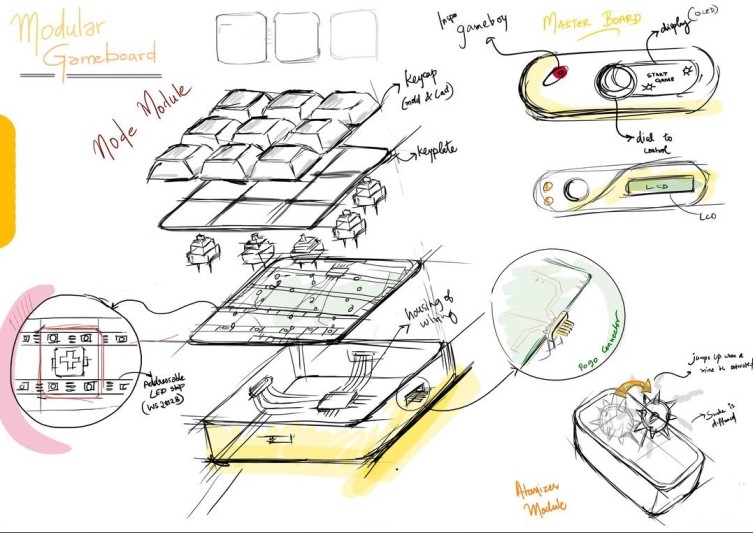
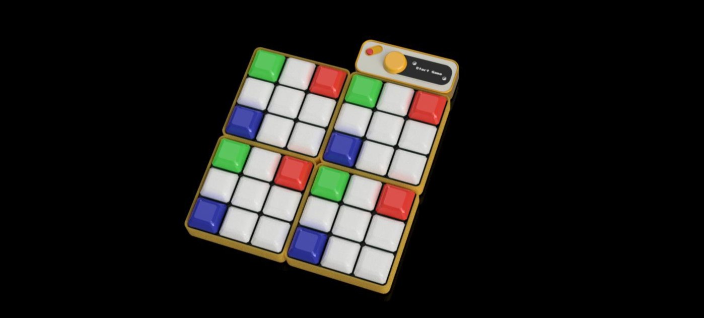
Modular GamePad
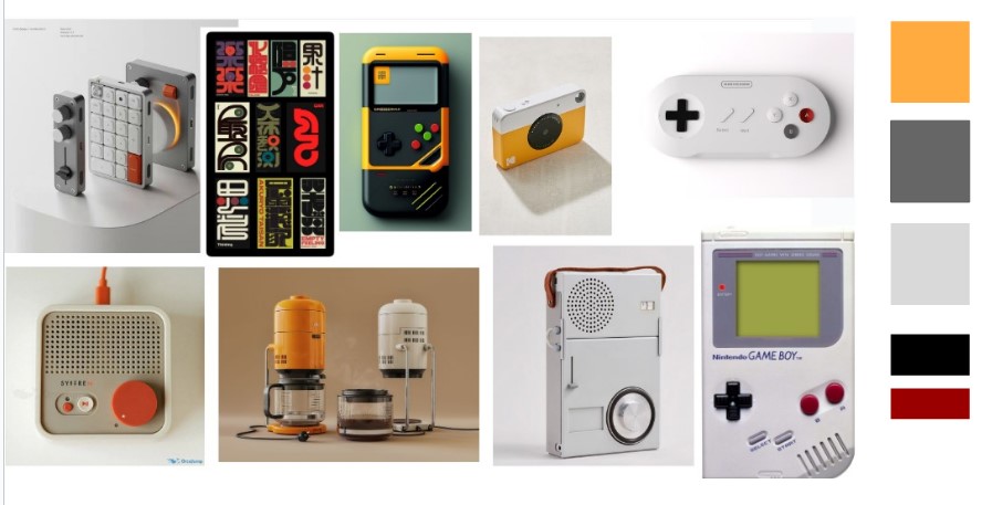
Inspo Board
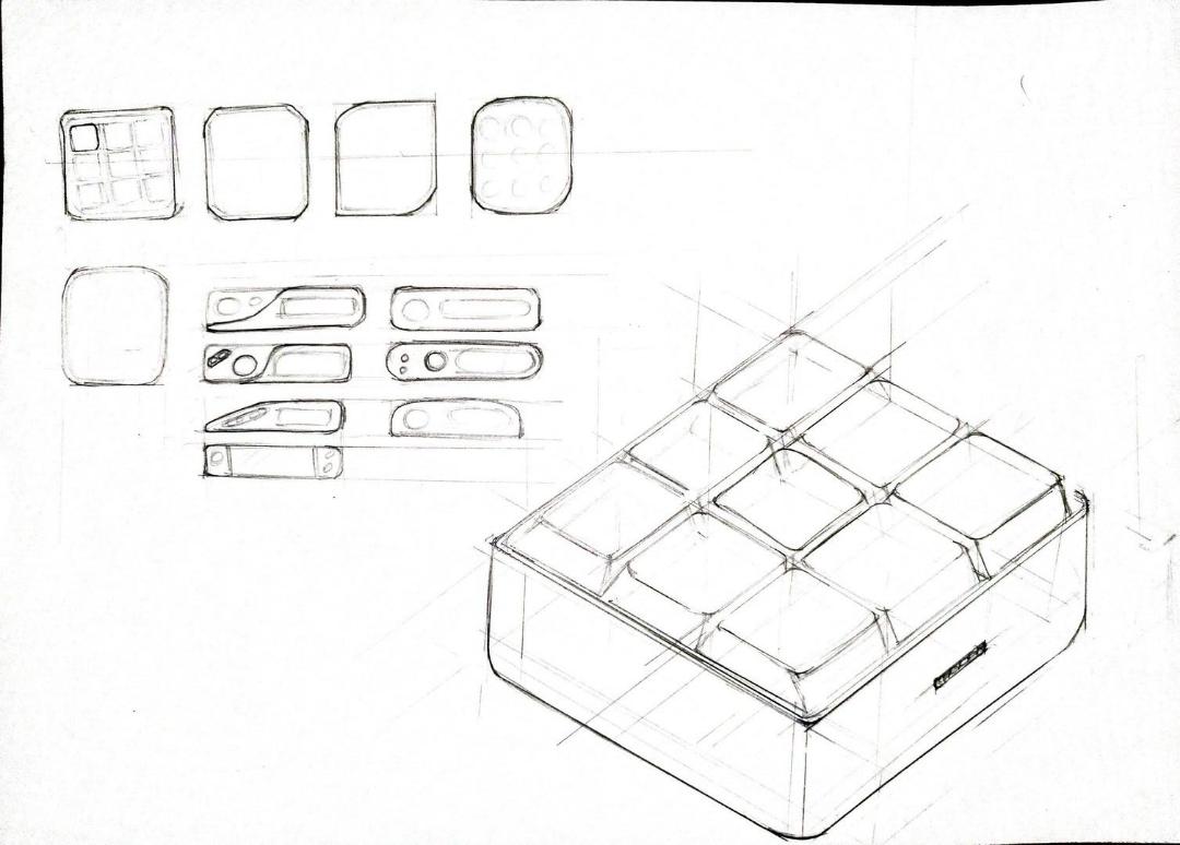
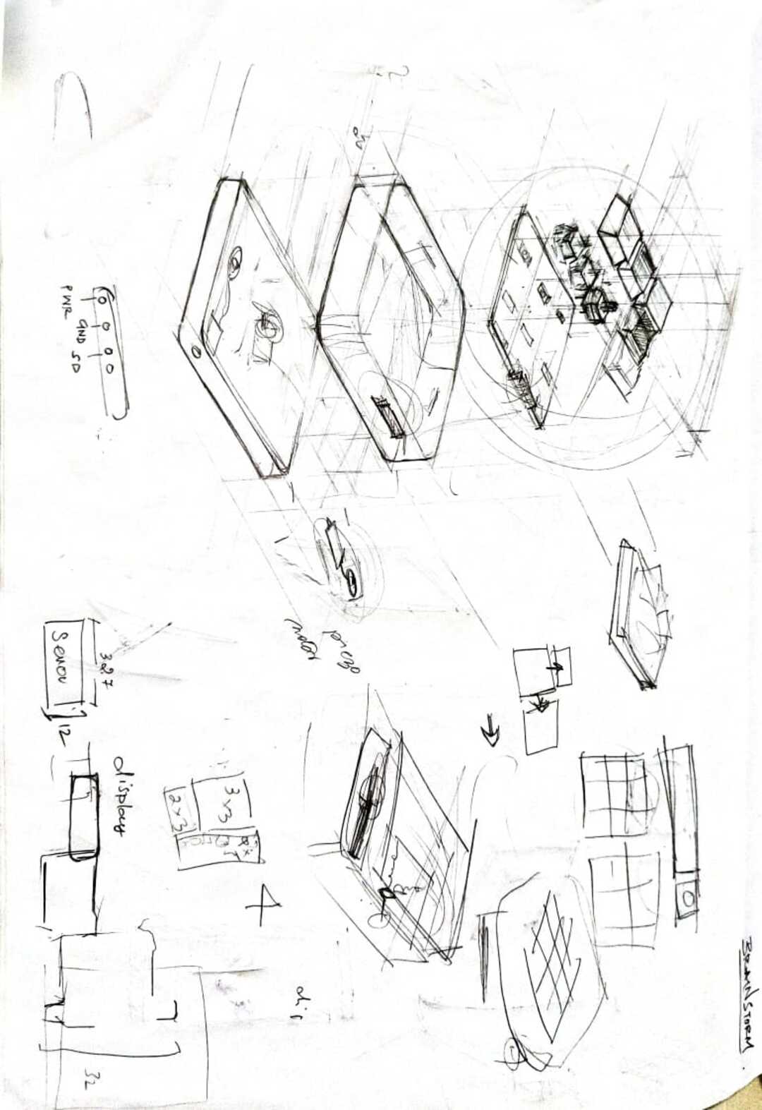
Exploration Sketches
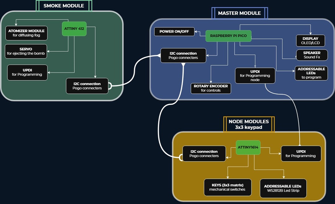
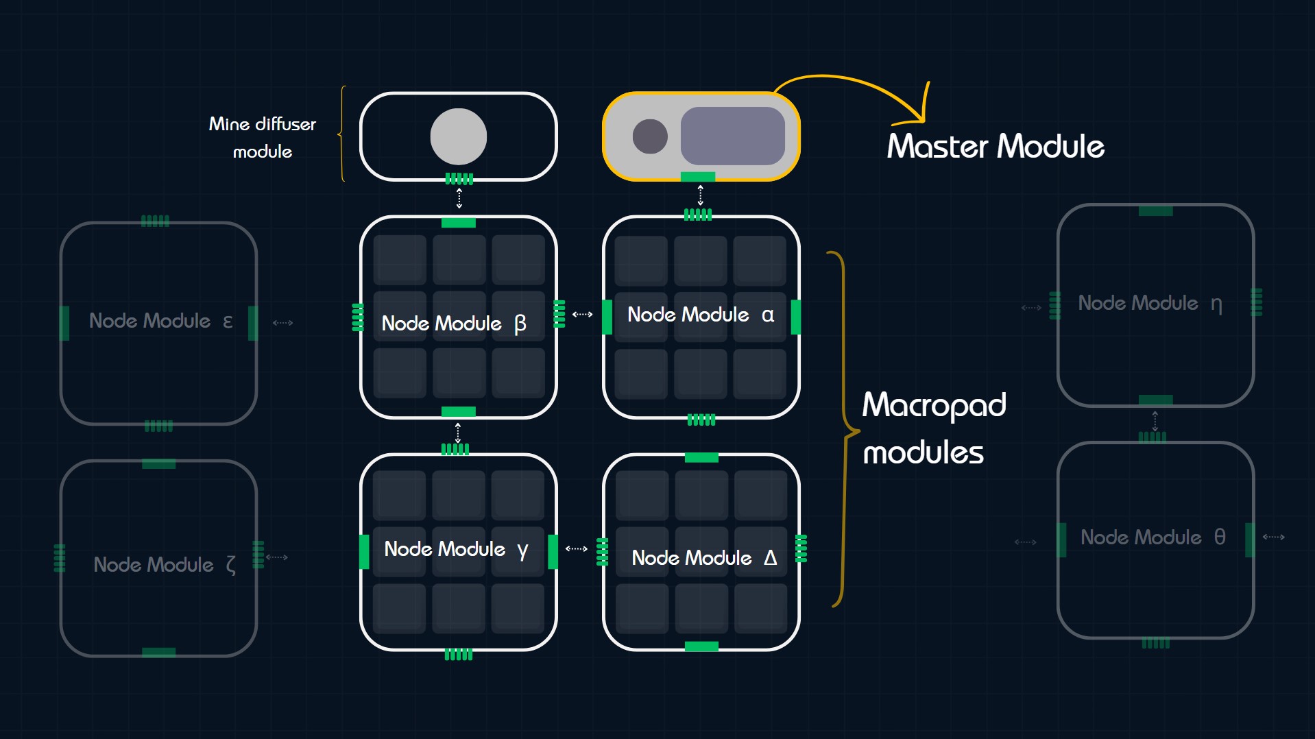
Block Diagram
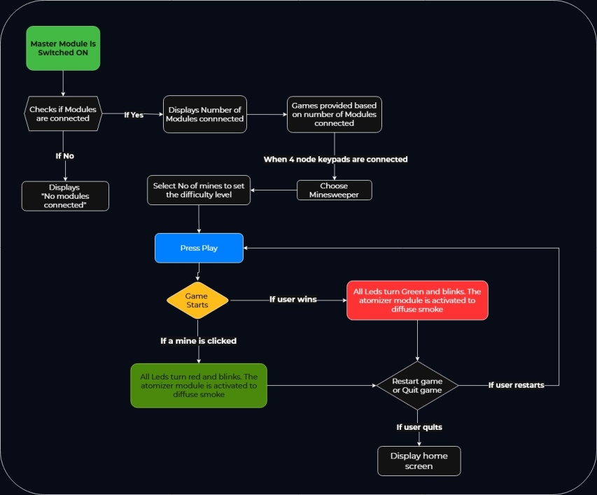
Userflow
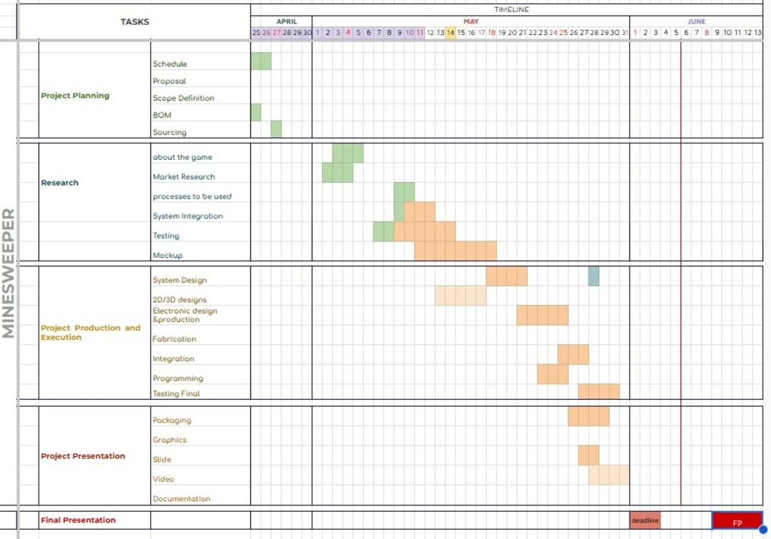
Schedule
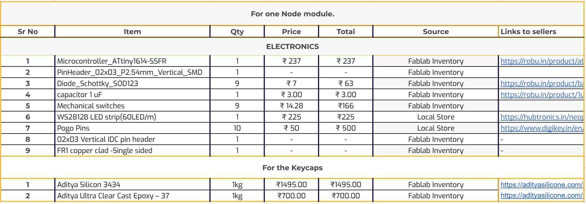
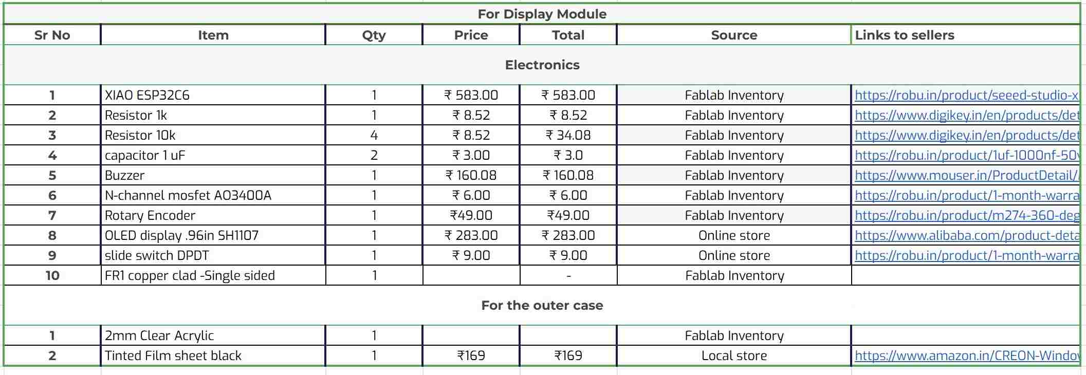
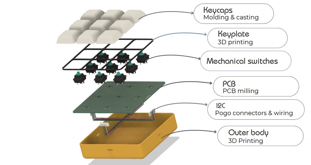
Bill of Materials
Modular Connections
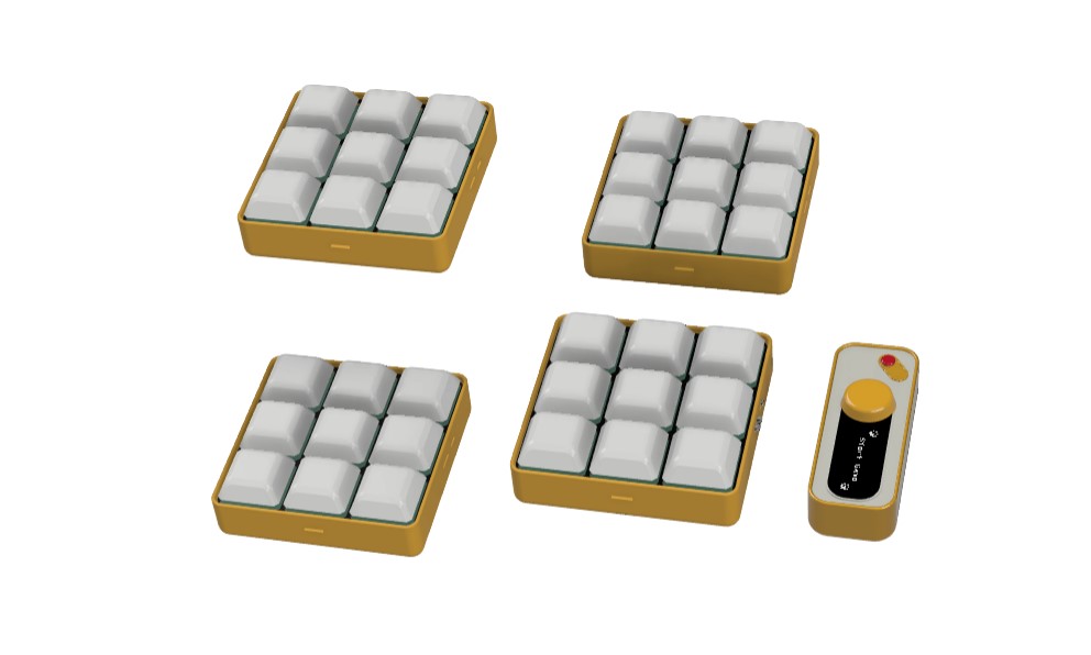
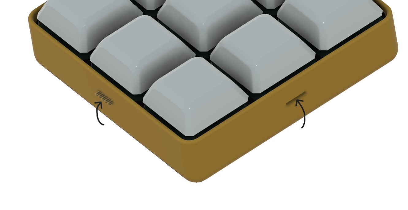
Design
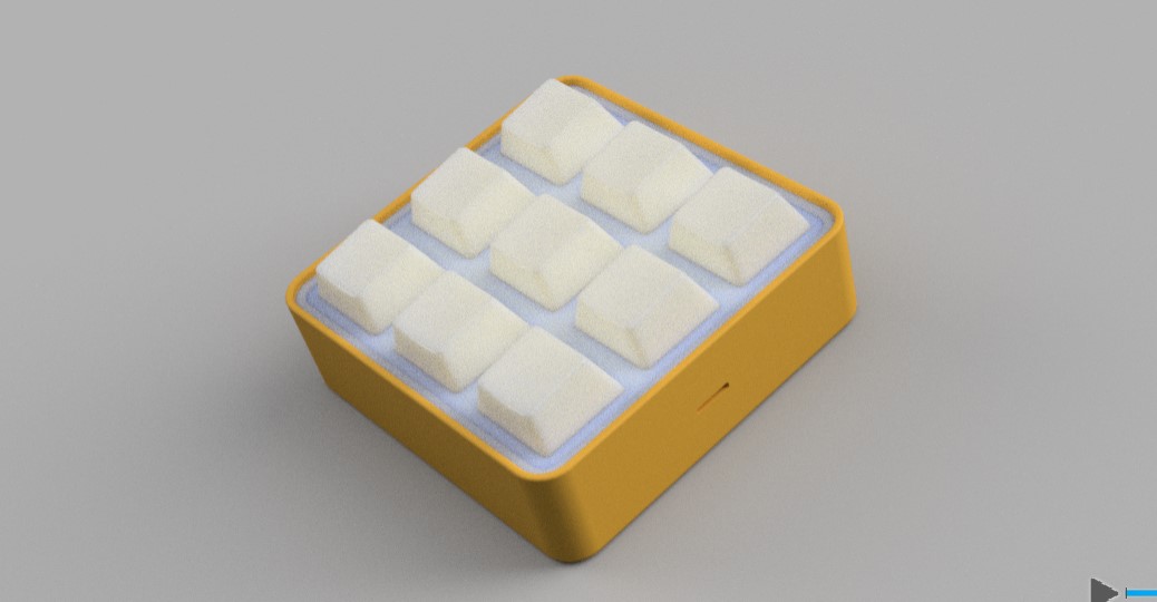
Iteration 2

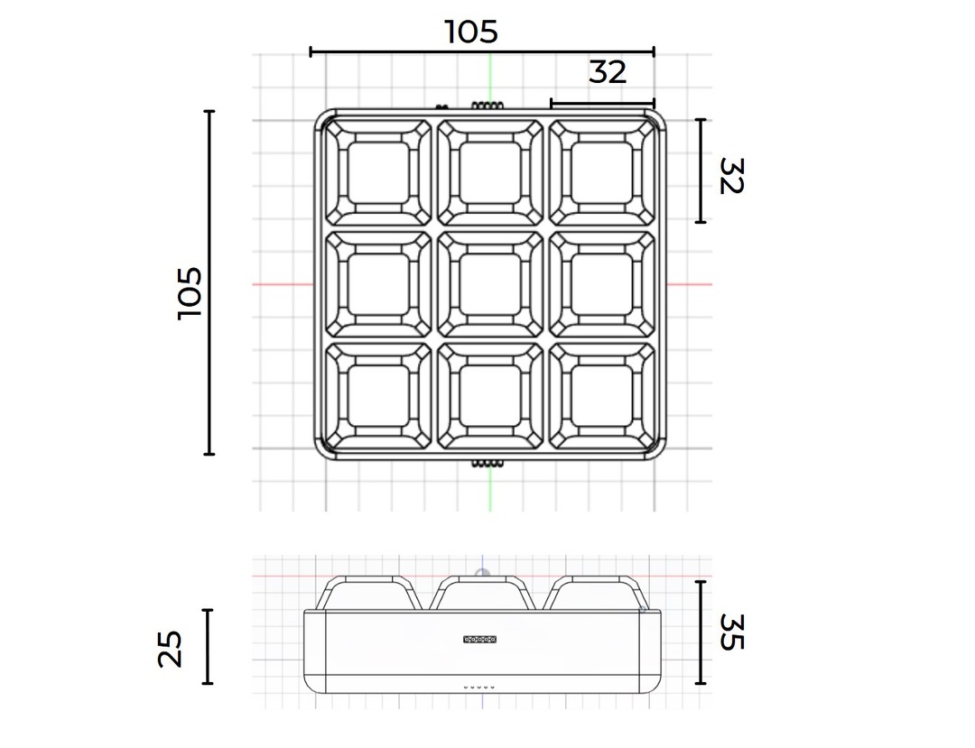

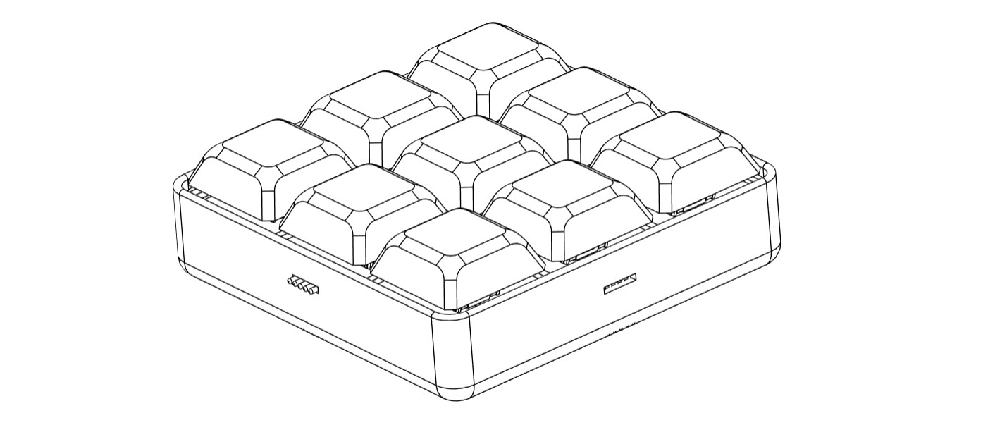
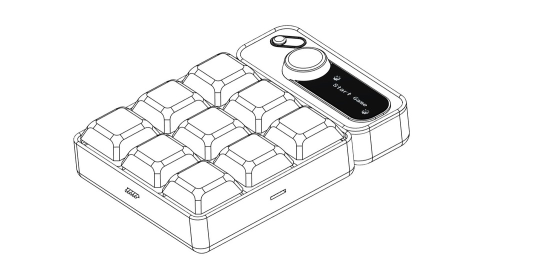
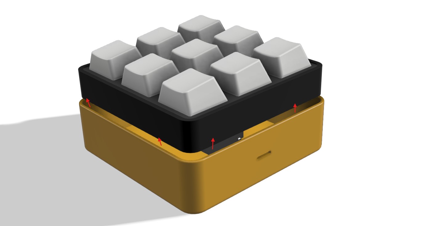
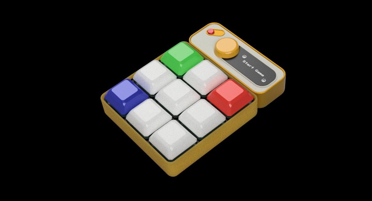
CAD models
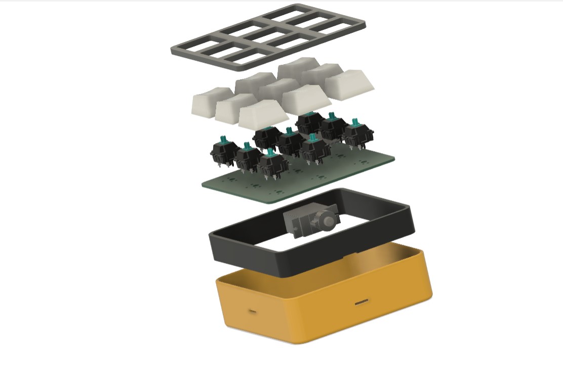
Exploded view
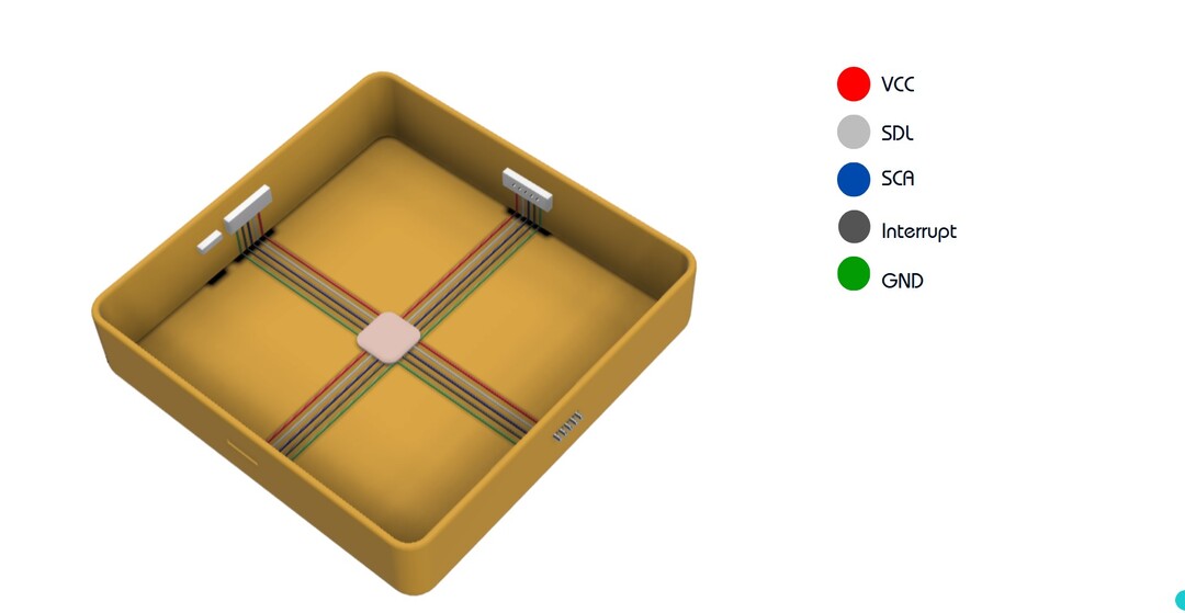
Connectors and Wiring
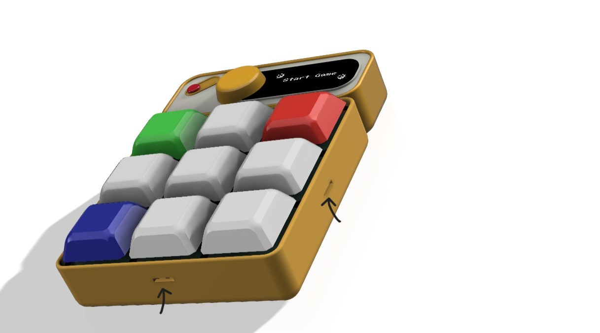
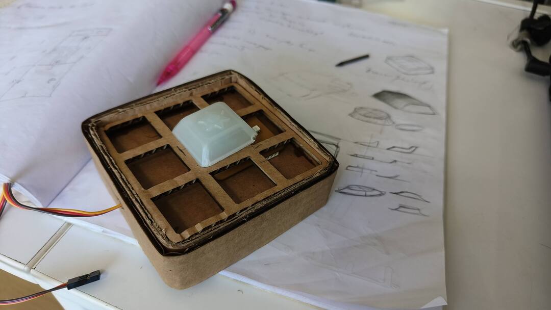
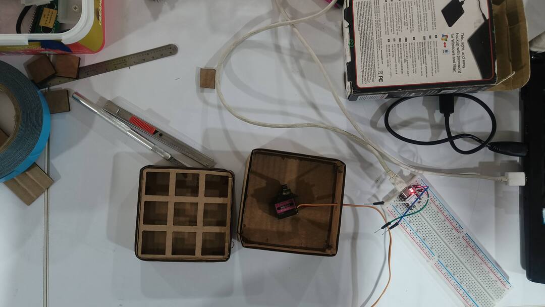
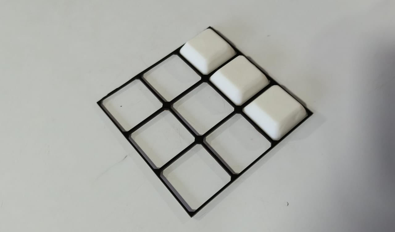
Mockup2
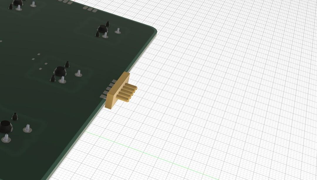
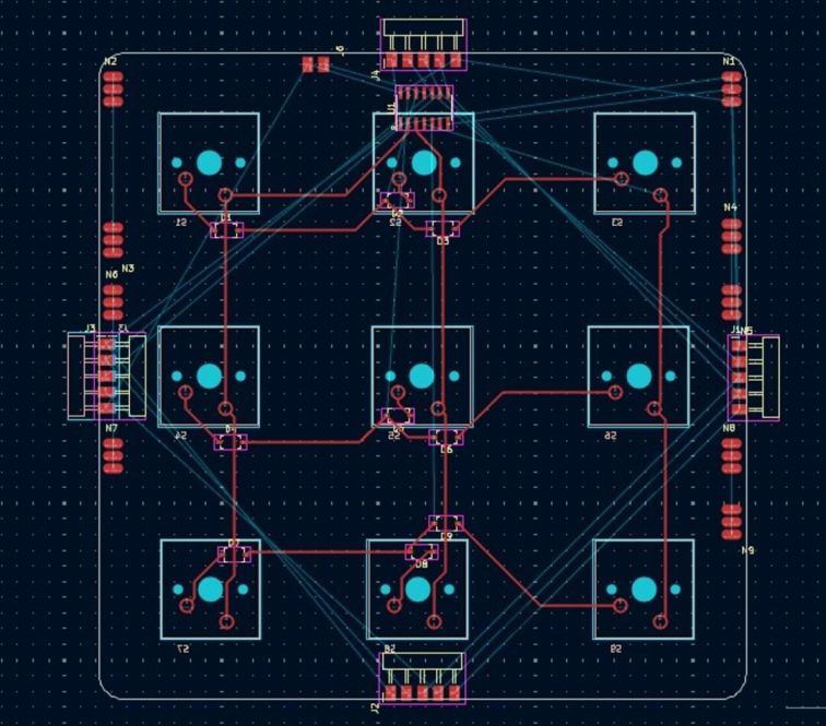
PCB for module
To do