11.Networking and Communication
This week's brief:
Group assignment:
GROUP ASSIGNMENT
You can view our group assignment here!
INDIVIDUAL ASSIGNMENT
Learning about I2C
I2C, short for Inter-Integrated Circuit, a serial communication protocol that uses two wires to connect devices It's commonly used for short-distance communication between microcontrollers and peripheral devices like sensors and displays. The I2C protocol involves using two lines to send and receive data: a serial clock pin (SCL) that the Arduino Controller board pulses at a regular interval, and a serial data pin (SDA) over which data is sent between the two devices. As the clock line changes from low to high (known as the rising edge of the clock pulse), a single bit of information is transferred from the board to the I2C device over the SDA line.Design
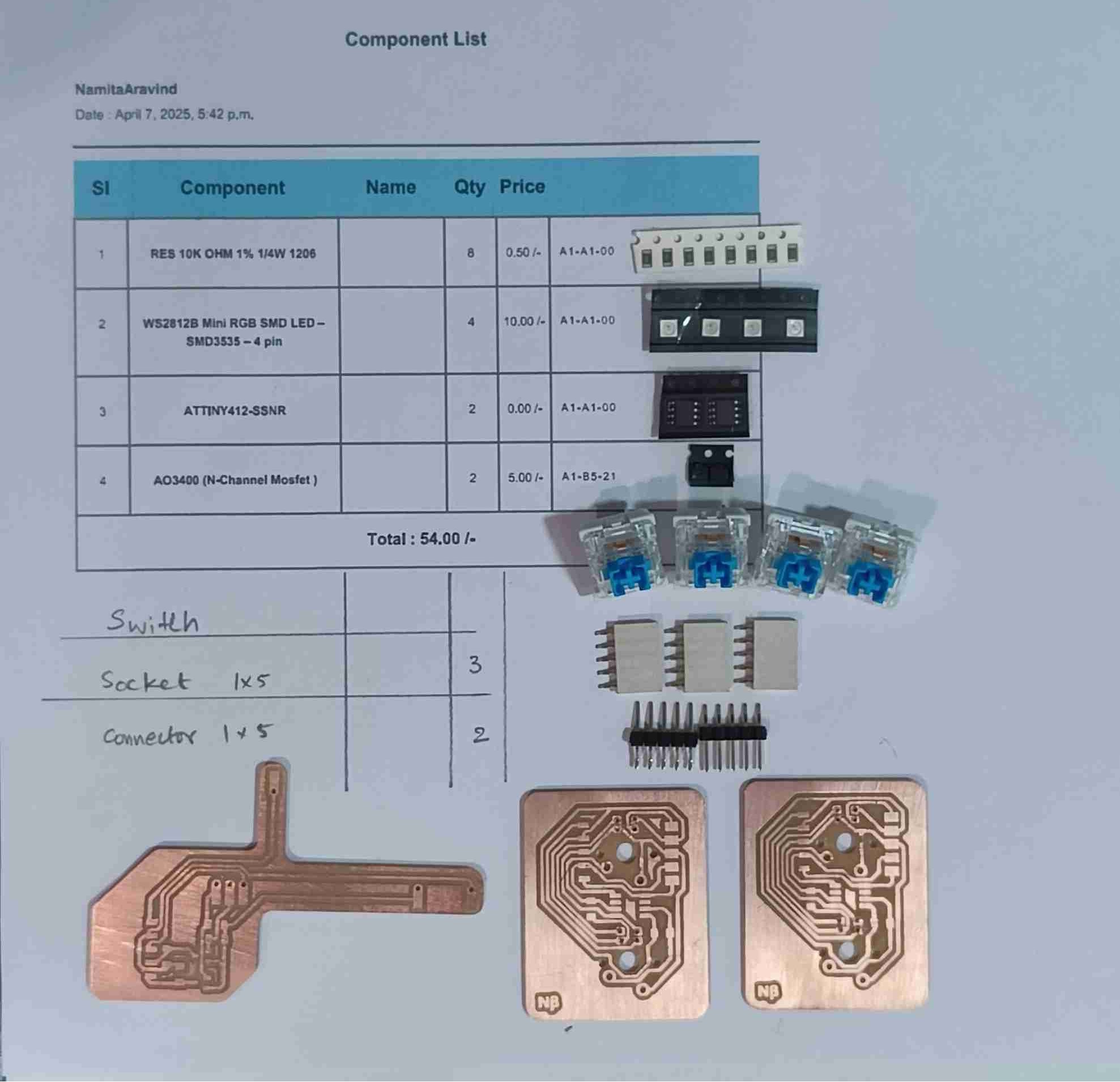
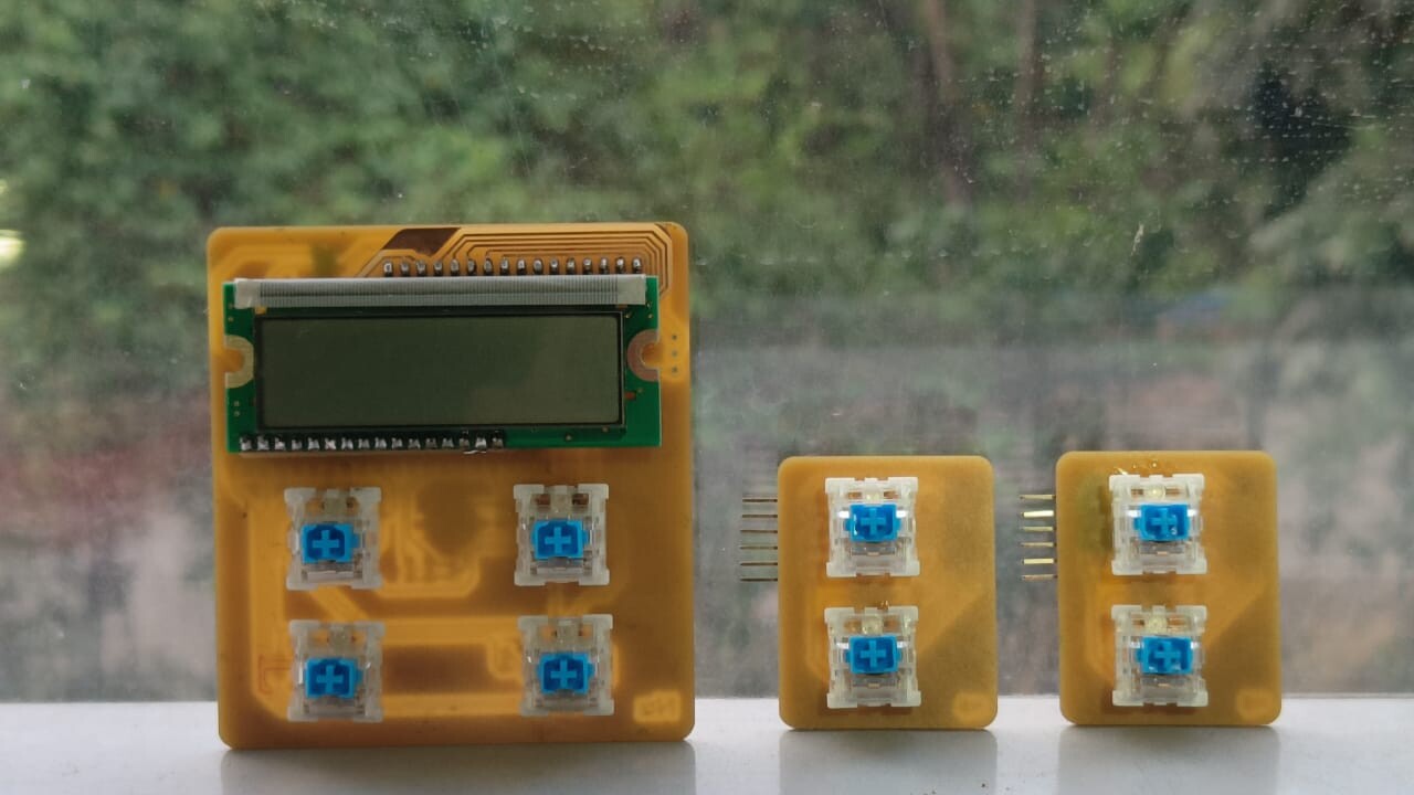
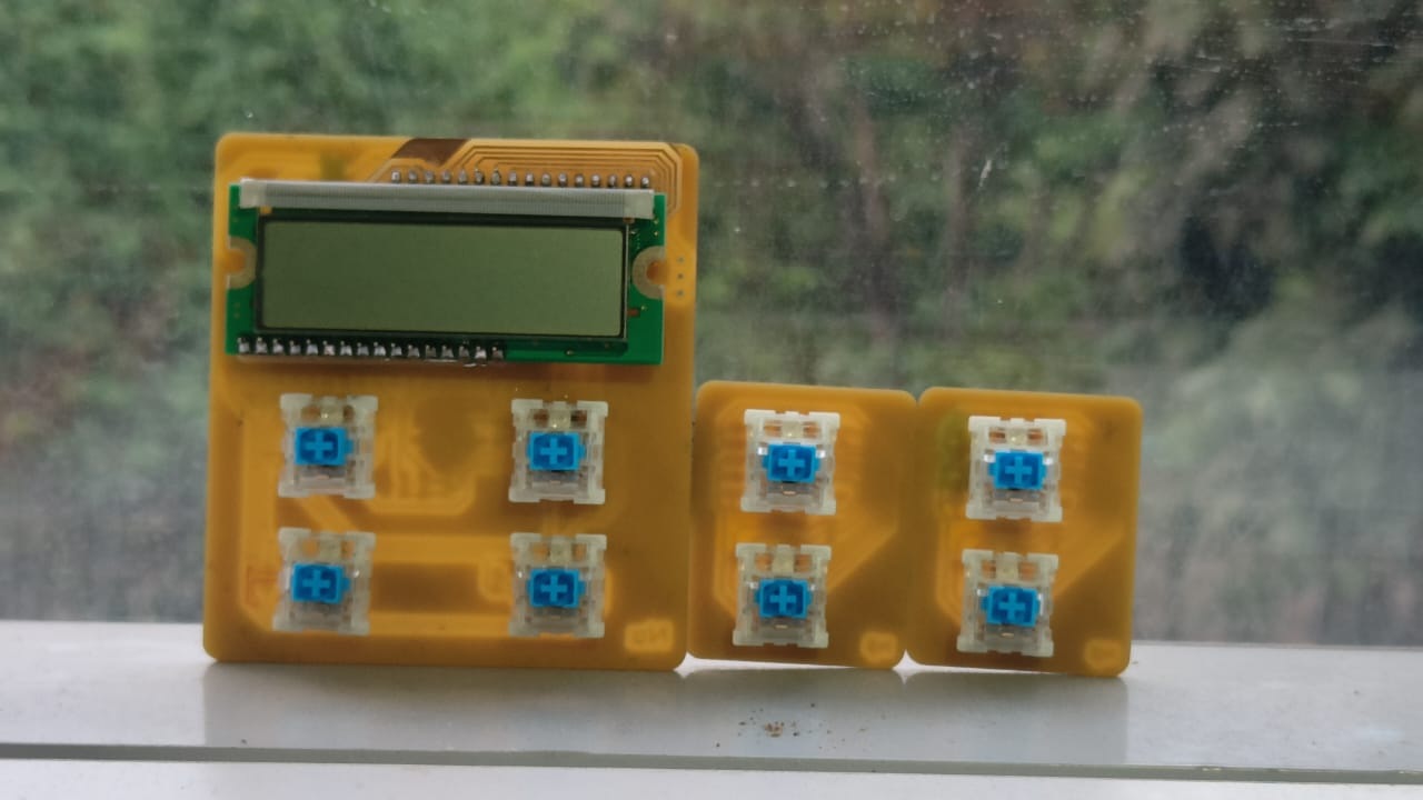
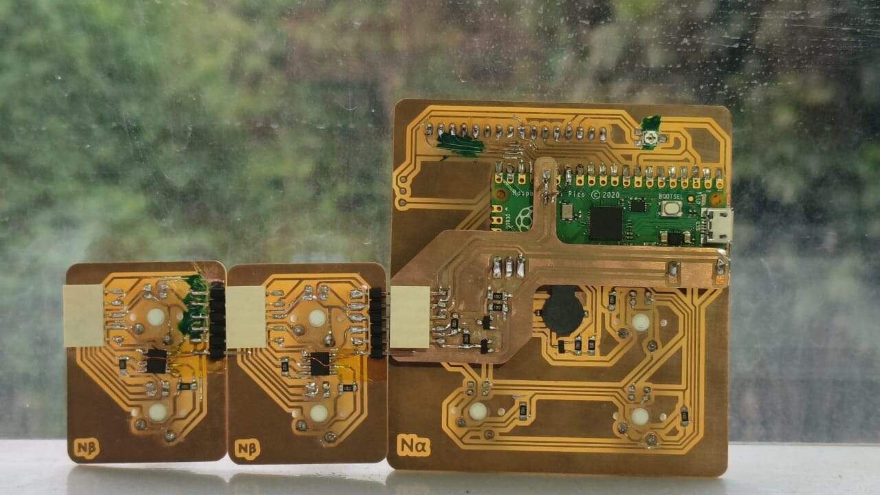
For this week I had an idea that i have been waiting on to explore so that I can see whether it could be implemented to my final project. My final project board has way too many switches as well as the LEDs attached to each of the switches. It would be quite impractical to fit it all into a single PCB with the amount of of connections it would require. I also had this idea of the board being expandable to increases the difficulty factor of the game too. This led me to think of ways that i could make the board modular and have the number of keys be added or decreased according to the user.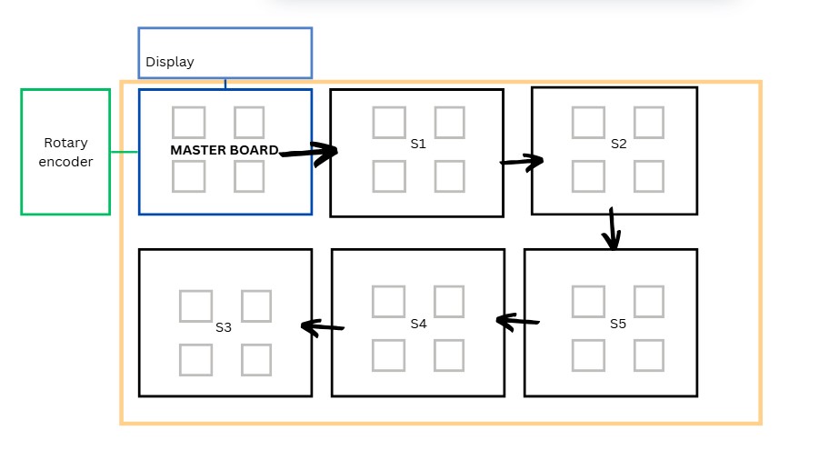 Learning about the I2C connections drove me to to think of making a grid of keys that could be attached
side by side to make the board bigger . As all the keys have the same functions it seemed like a good option to go
ahead with.
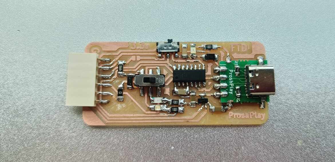
The prior week I had made a macro pad with all the elements necessary, i thought of making that my master board. I
also would like to
incorporate the PCB that I made during input week to make use of the functionality of the rotary encoder to control
the display of the macropad .
Learning about the I2C connections drove me to to think of making a grid of keys that could be attached
side by side to make the board bigger . As all the keys have the same functions it seemed like a good option to go
ahead with.
The prior week I had made a macro pad with all the elements necessary, i thought of making that my master board. I
also would like to
incorporate the PCB that I made during input week to make use of the functionality of the rotary encoder to control
the display of the macropad .
Making the PCB
Additions to the Master PCB
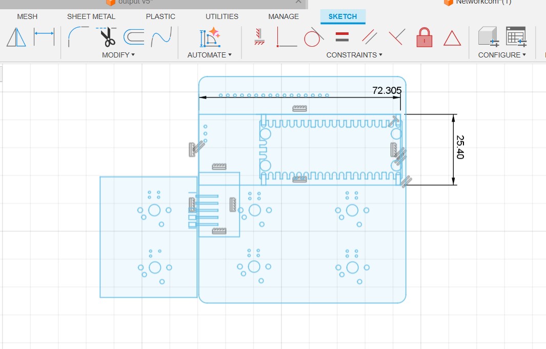
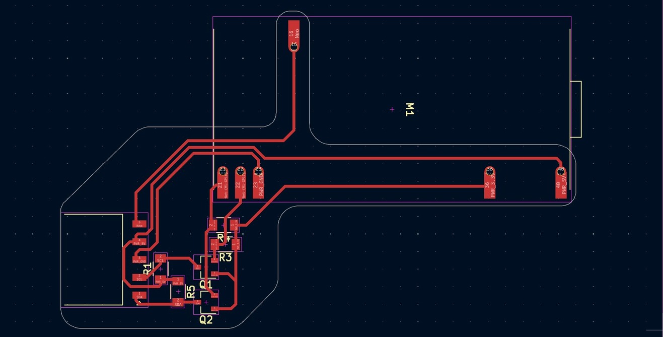
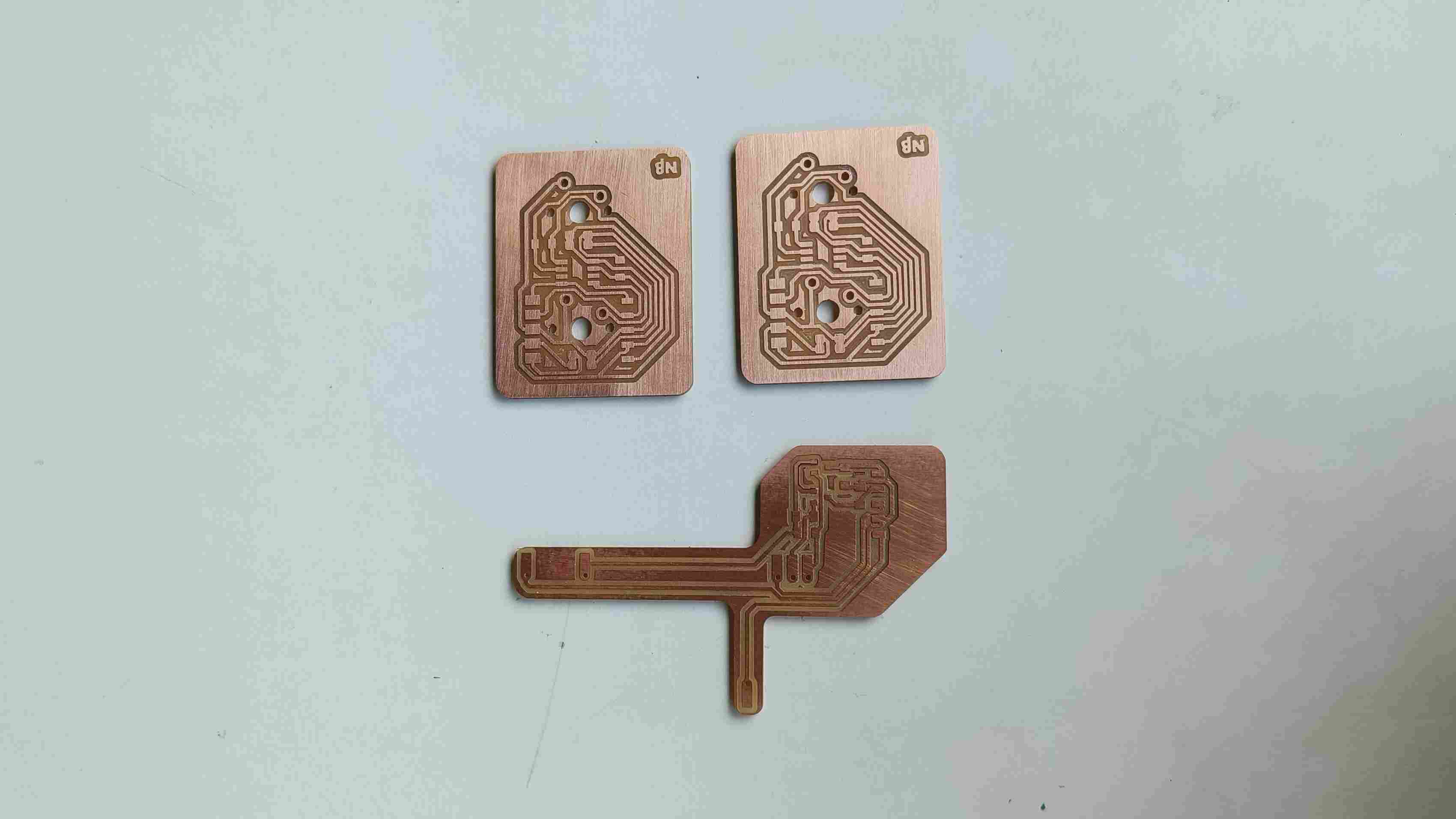
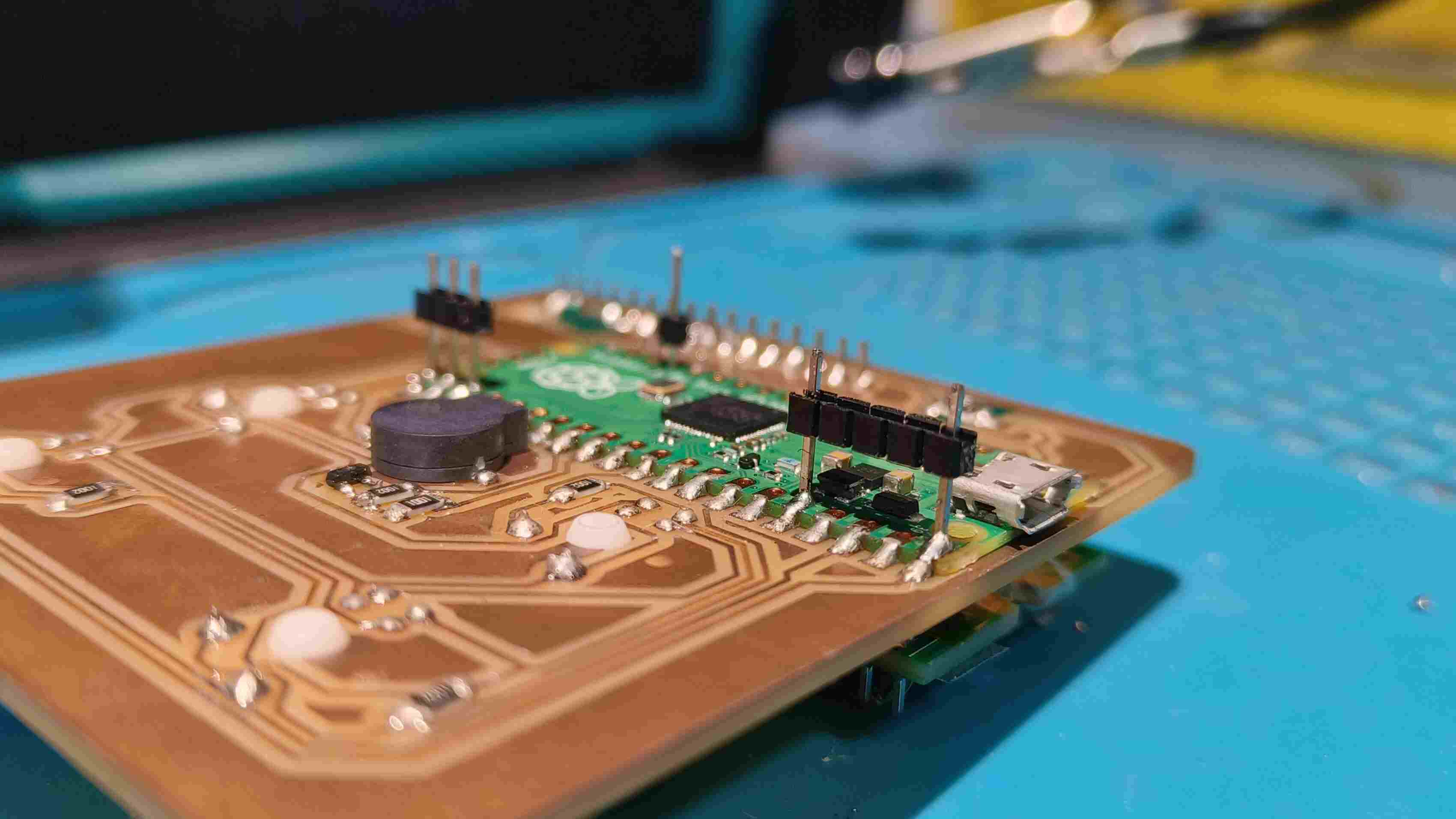
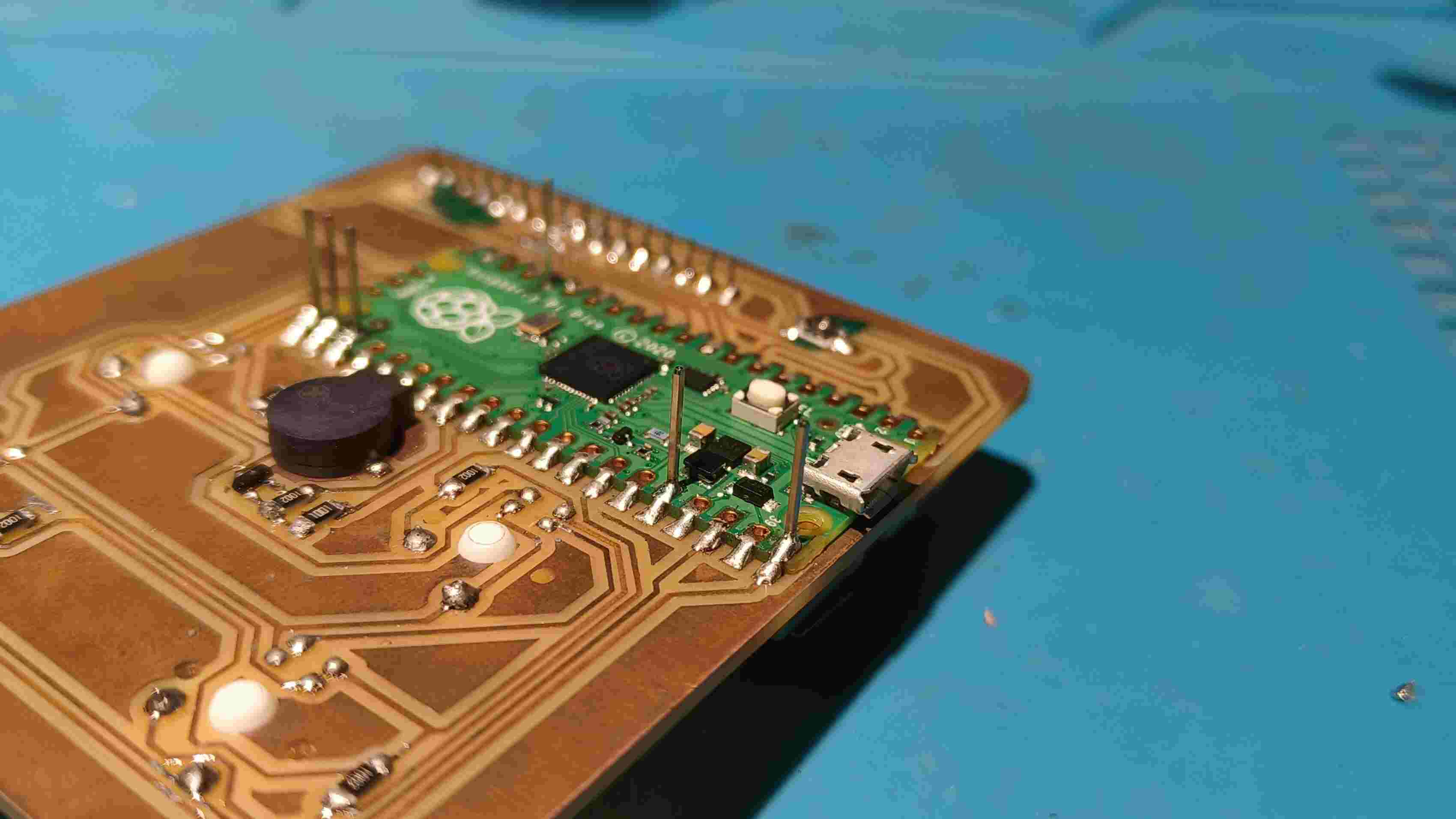
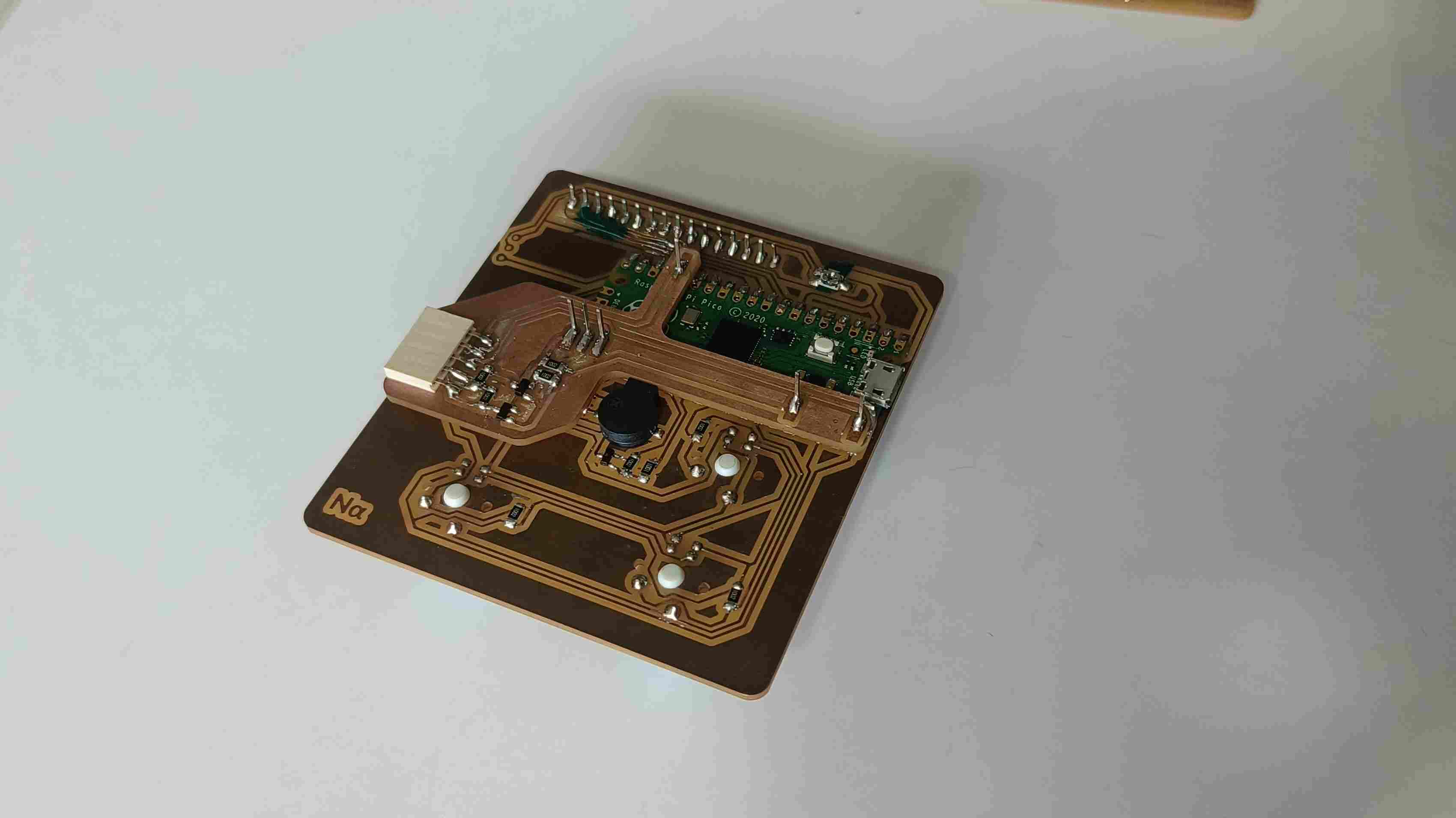
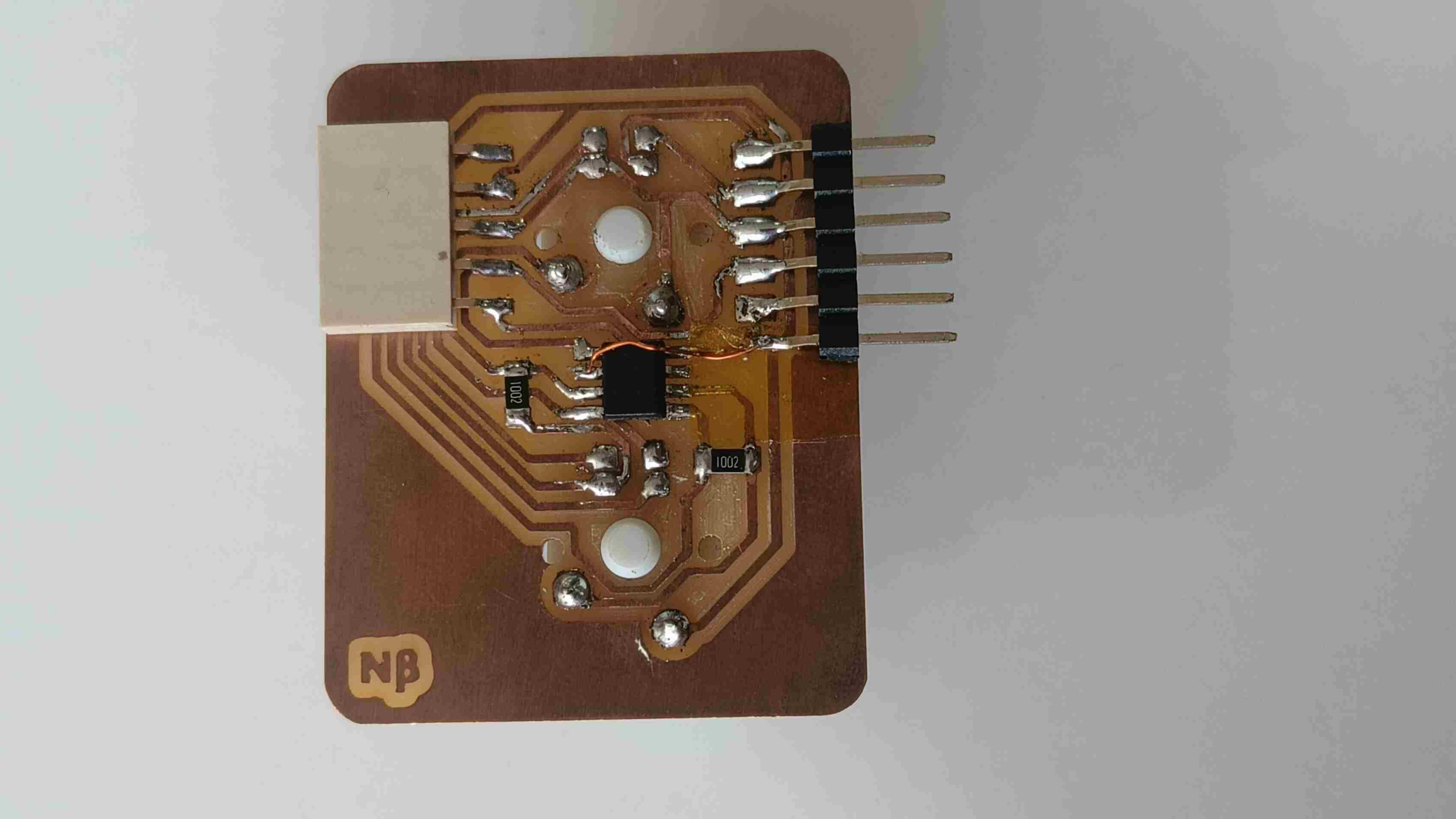
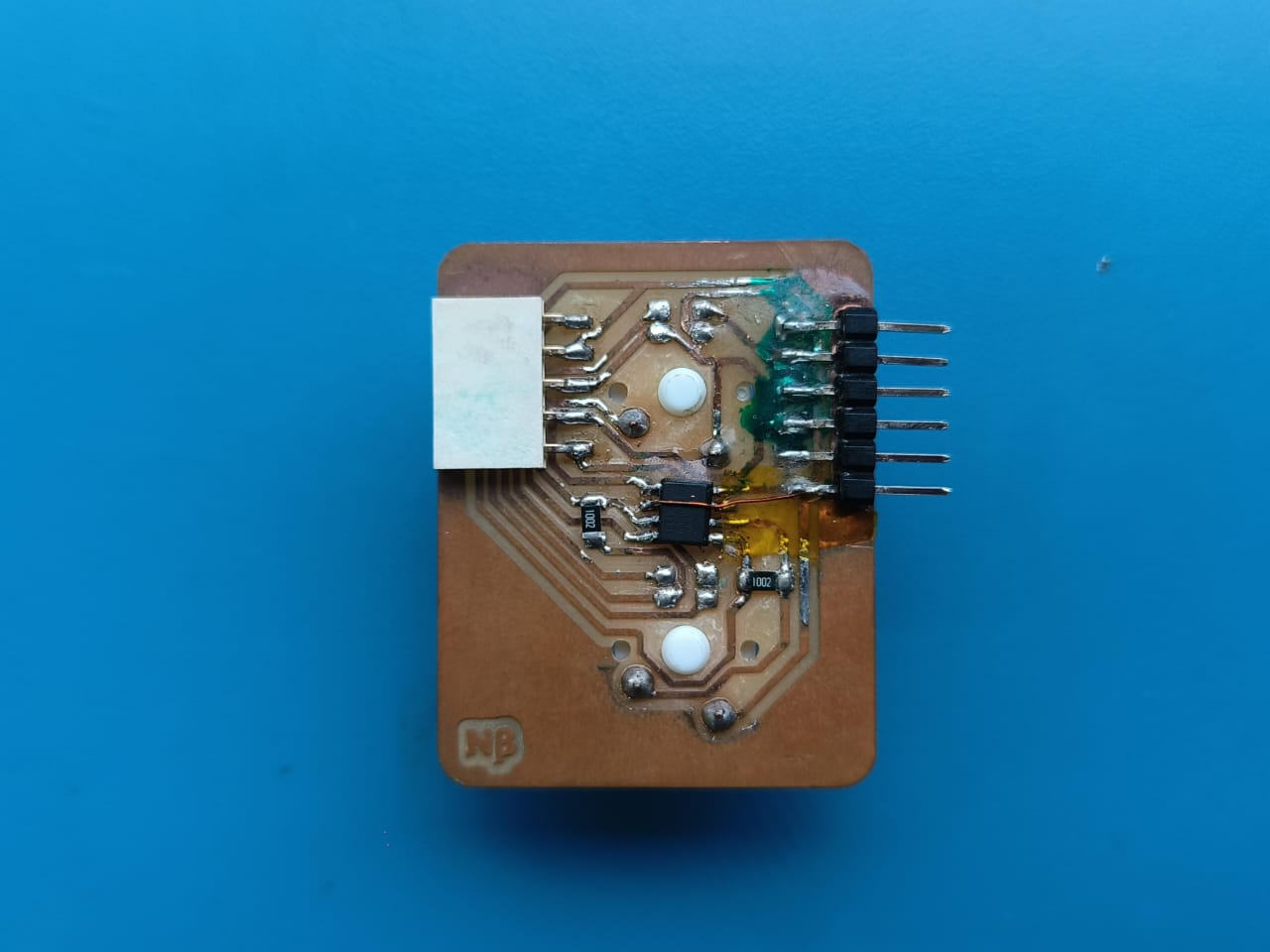
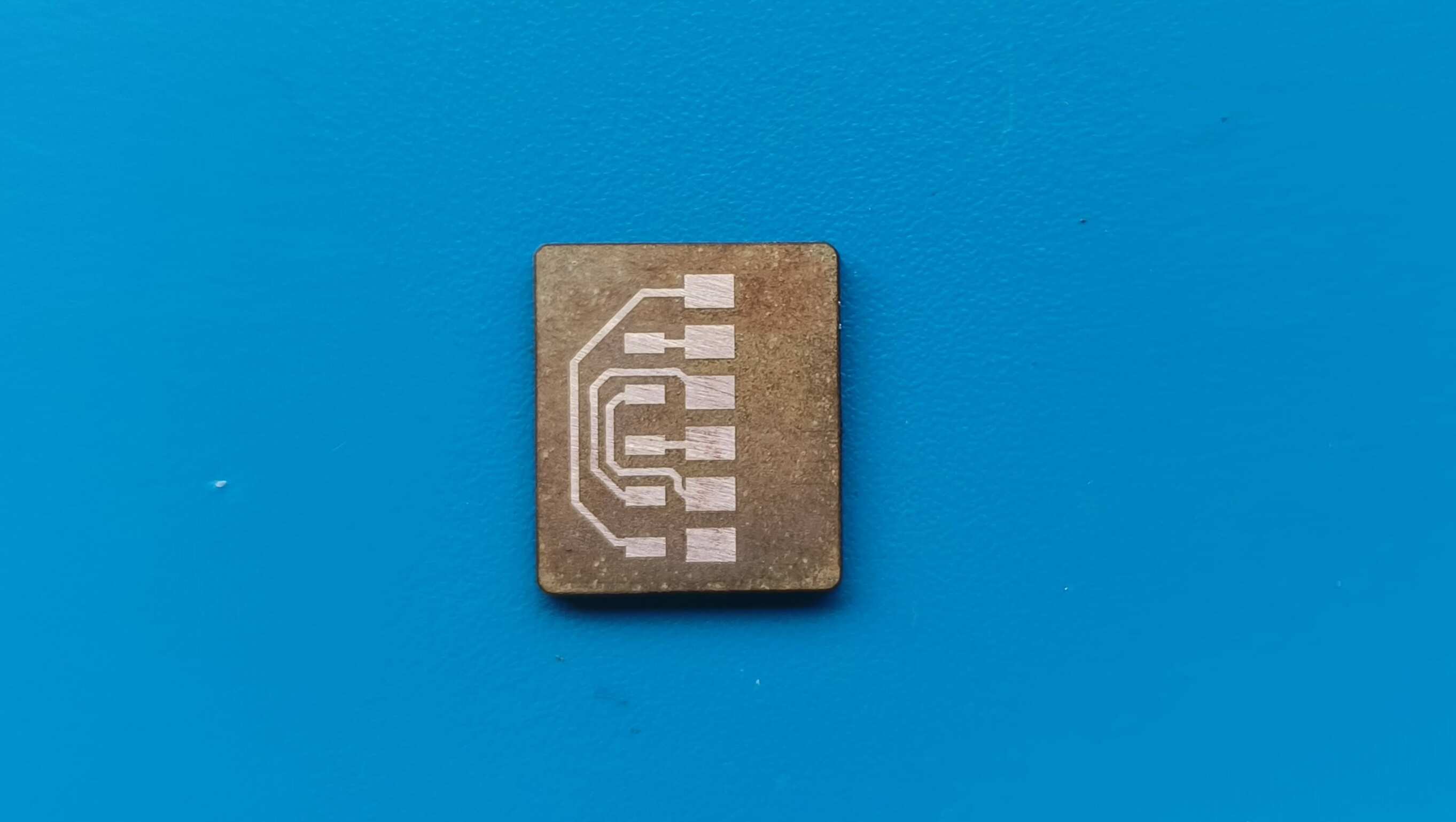
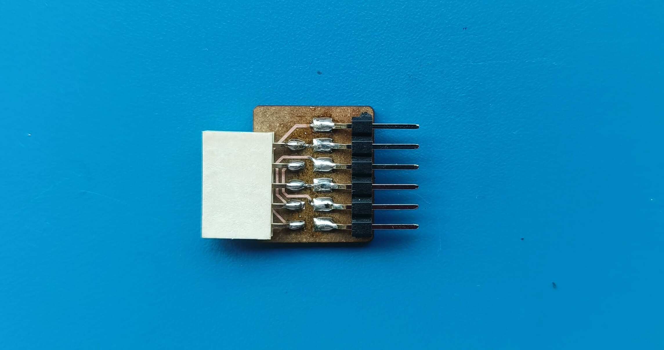
The master board was going to be my macropad made during output week, but i need to make some additional connections for I2C . To do so i had to make another smaller PCB ,with the traces according to the pins and connectors, to be mounted on the PCB.
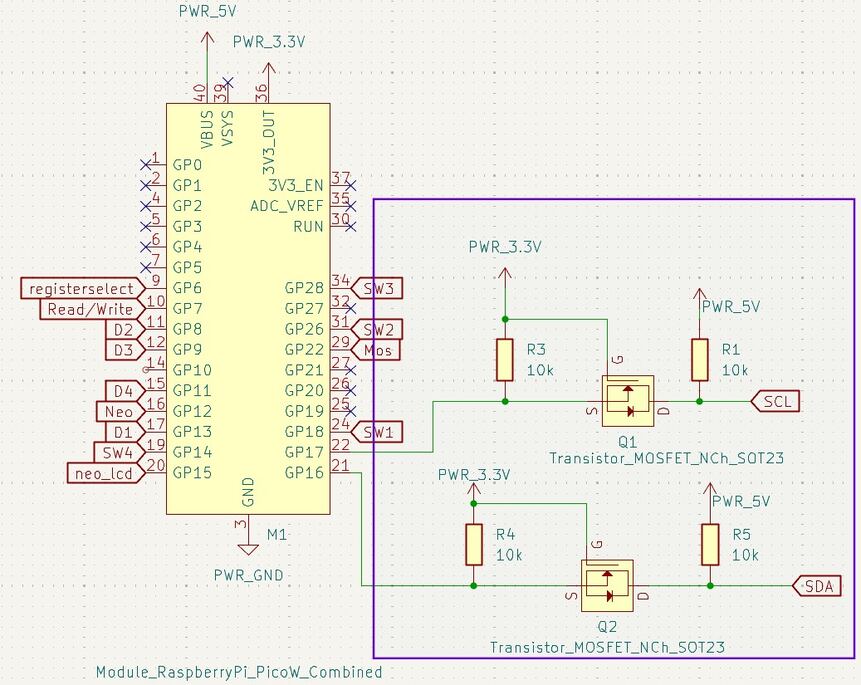
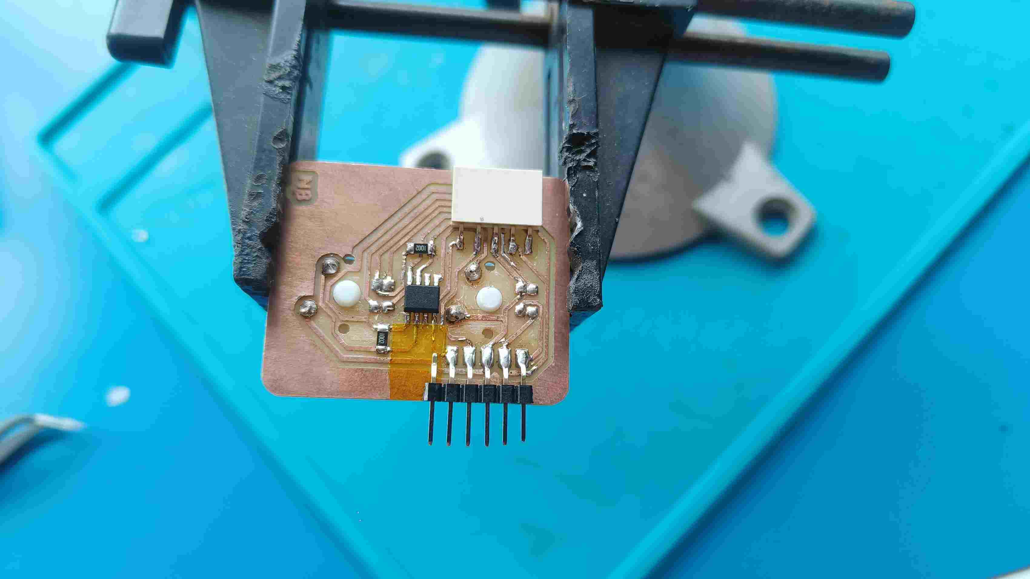
Logic level Shifter
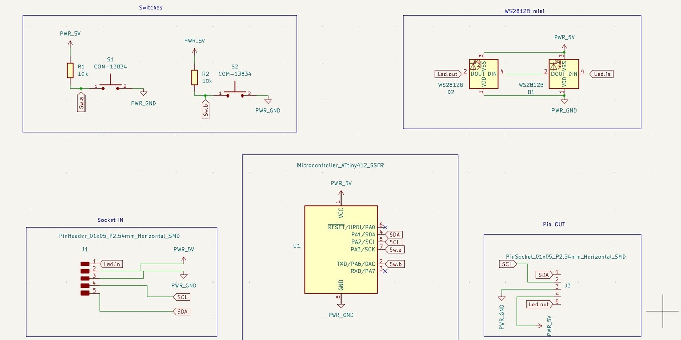
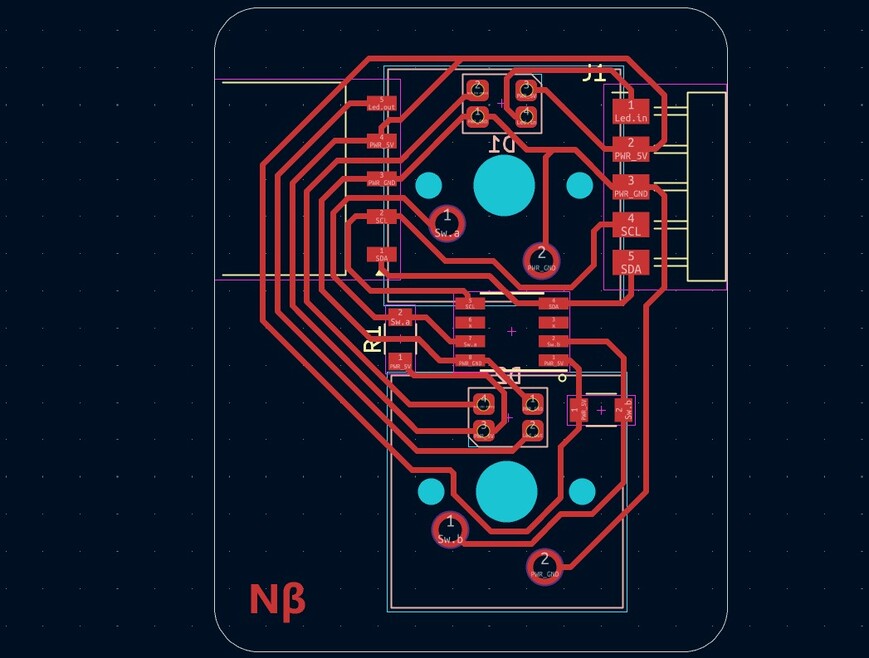
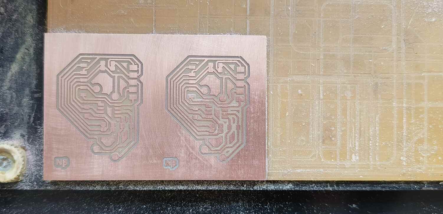
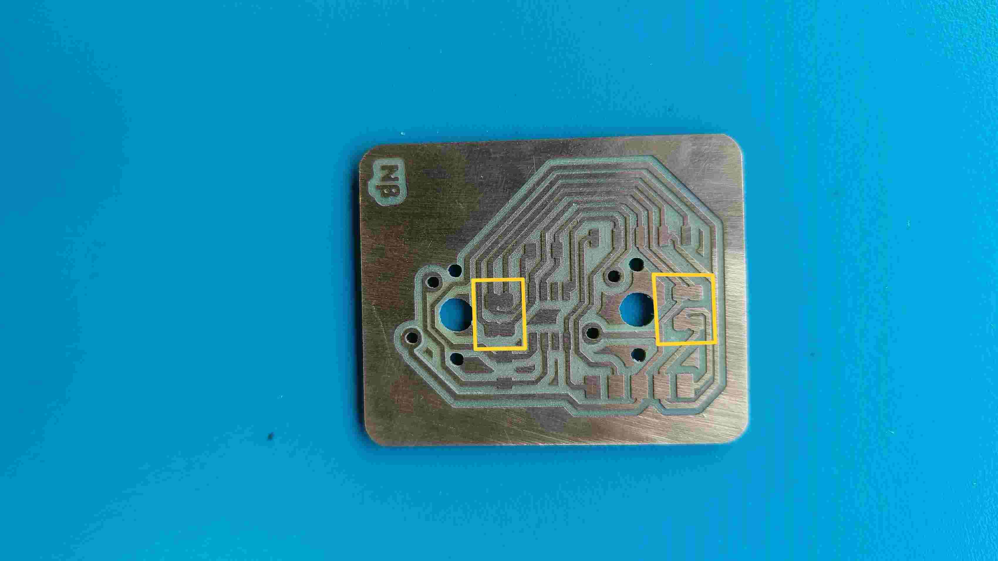
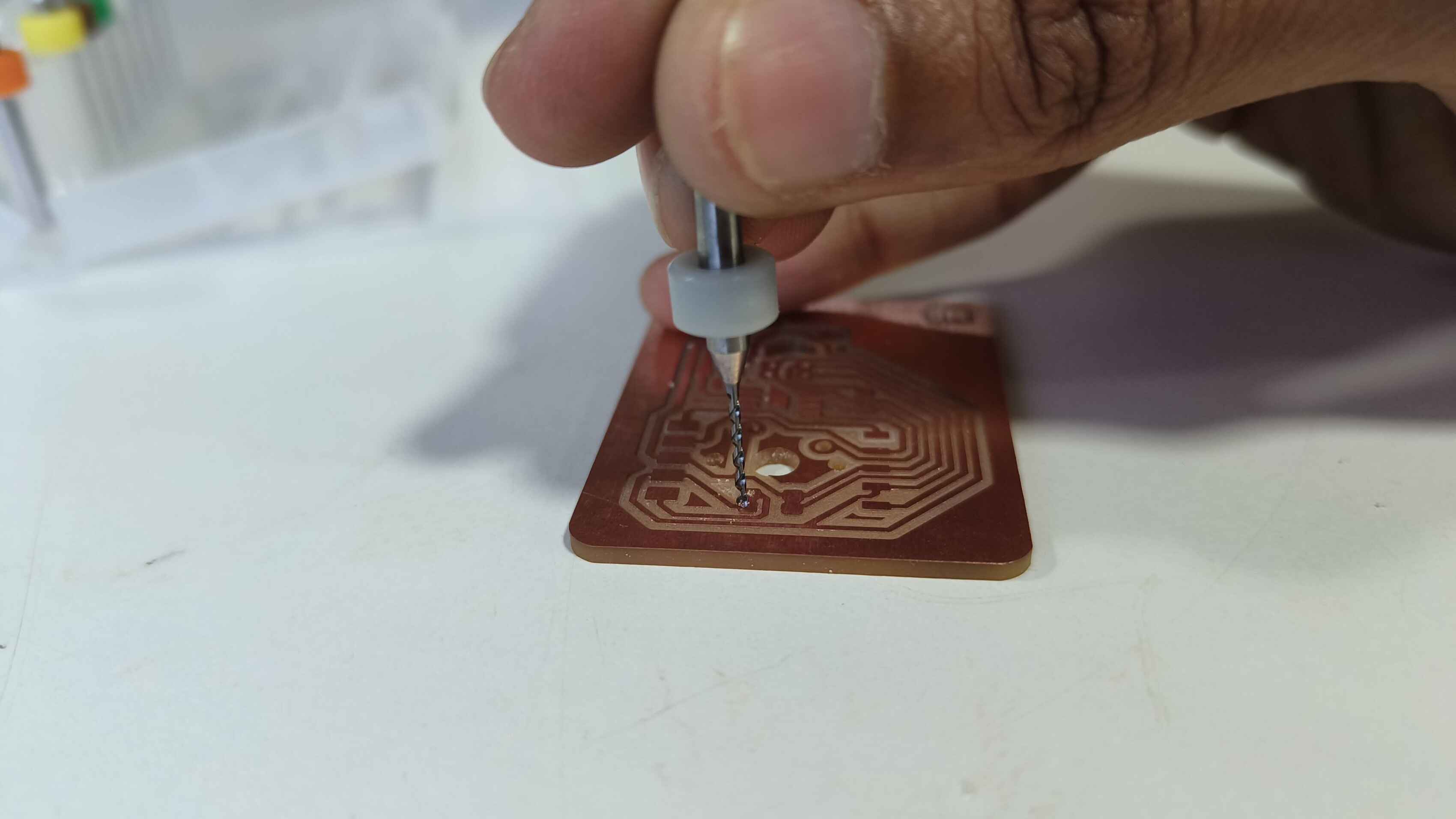
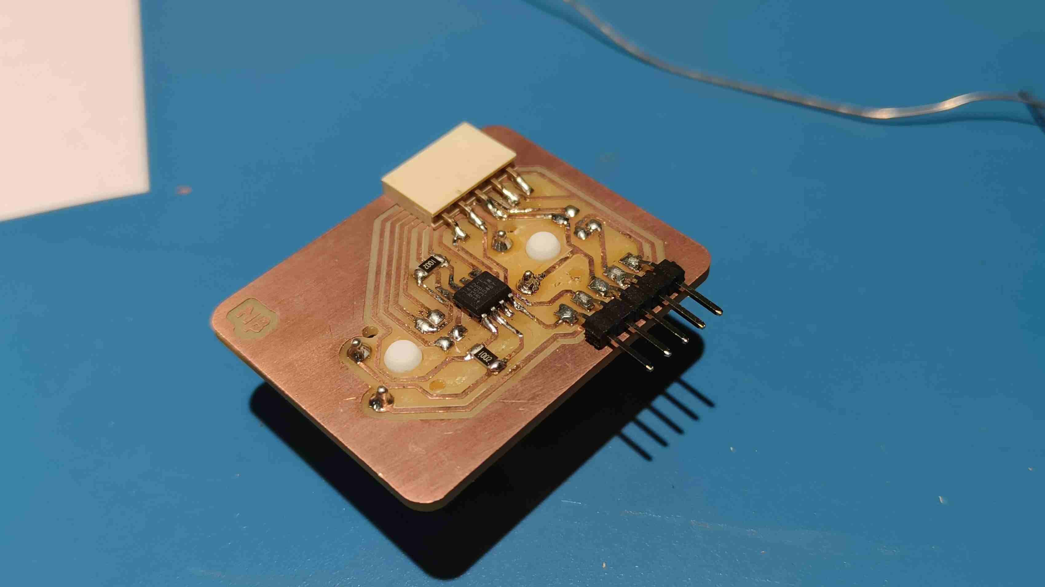
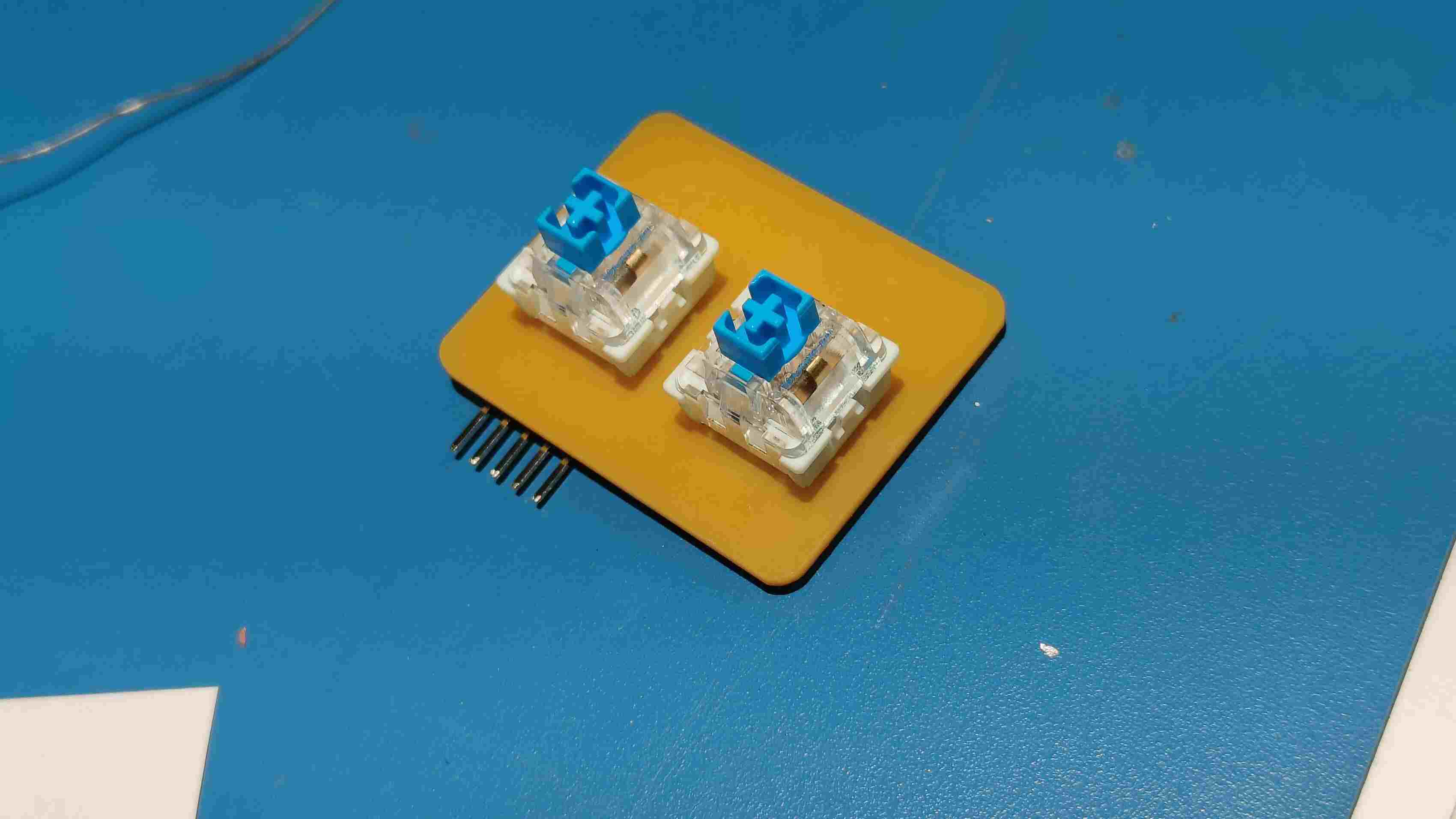
Making the Secondary PCB
Programming
Coming to programming i had to basically program my master board using a secondary code and Beta nodes using a master read write code. So esswntially i was working with mutiple nodes with a master code sending data to a single master borad but with a secondary code.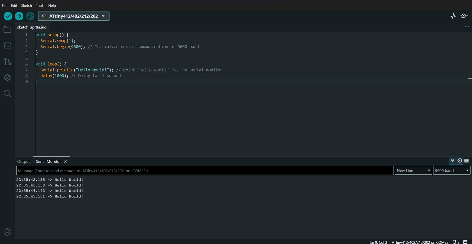
  void setup() {
    pinMode(0,INPUT);//pin no. of switch1
     pinMode(4,INPUT);//pin no. of switch2
    Serial.swap(1);
    Serial.begin(9600); // Initialize serial communication at 9600 baud
  }

  void loop() {

   if(digitalRead(0)==LOW){
    Serial.println("Hello World from switch1!"); // Print "Hello World!" to the serial monitor
    }
    delay(100);
   if(digitalRead(4)==LOW){
    Serial.println("Hello World from switch2!"); // Print "Hello World!" to the serial monitor
    }
      delay(100);
  }
Now i can start to give the Test codes for communication:
For Beta board 1
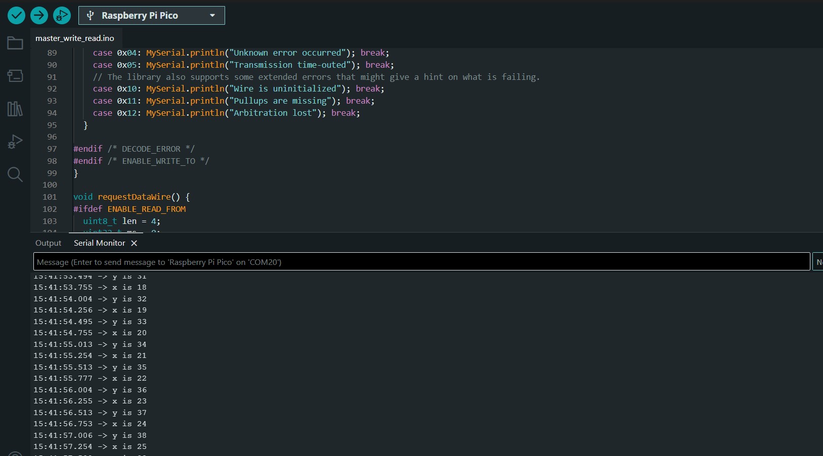
// Wire Master Writer // by Nicholas Zambetti < http://www.zambetti.com> // Demonstrates use of the Wire library // Writes data to an I2C/TWI slave device // Refer to the "Wire Slave Receiver" example for use with this // Created 29 March 2006 // This example code is in the public domain. #includeFor Beta board 2void setup() { Wire.begin(); // join i2c bus (address optional for master) } byte x = 0; void loop() { Wire.beginTransmission(8); // transmit to device #8 Wire.write("x is "); // sends five bytes Wire.write(x); // sends one byte Wire.endTransmission(); // stop transmitting x++; delay(500); }
// Wire Master Writer // by Nicholas Zambetti < http://www.zambetti.com> // Demonstrates use of the Wire library // Writes data to an I2C/TWI slave device // Refer to the "Wire Slave Receiver" example for use with this // Created 29 March 2006 // This example code is in the public domain. #includeThen i connected both nodes to the master board and used the Slave write code to program the master board to recive message from the nodes.void setup() { Wire.begin(); // join i2c bus (address optional for master) } byte y = 0; void loop() { Wire.beginTransmission(8); // transmit to device #8 Wire.write("y is "); // sends five bytes Wire.write(y); // sends one byte Wire.endTransmission(); // stop transmitting y++; delay(500); }
#includeThis was the output i got on the serial monitor.#define MySerial Serial // The serial port connected to the to the computer. // The complete example might not fit on some parts. In that case, you can easily // comment out some functionality. DECODE_ERROR bloats the code the most. #define ENABLE_WRITE_TO // Enables the master write functionality #define ENABLE_READ_FROM // Enables the master read functionality #define DECODE_ERROR // Prints status messages. char input[32]; int8_t len = 0; void setup() { Wire.setSDA(16); Wire.setSCL(17); Wire.begin(); // initialize master MySerial.begin(115200); // Use 115200 baud - this is the 2020's, and these are modern AVRs. } void loop() { if (MySerial.available() > 0) { // as soon as the first byte is received on Serial readFromSerial(); // read the data from the Serial interface if (len > 0) { // after the while-loop, if there was useful data, char c = input[0]; if (c == 'm' || c == 'M') { // If the first char is that sendDataWire(); // send the data over I2C to the slave } else { // otherwise requestDataWire(); // request data from I2C slave } } len = 0; // since the data was sent, the position is 0 again } } void readFromSerial() { while (true) { // in an endless while-loop while (MySerial.available() == 0) ; // means we've taken all the bytes in, and are still waiting for a cr/lf. char c = MySerial.read(); // read the next char, now that there's one available. if (c == '\n' || c == '\r') { // until a new line or carriage return is found break; // if so, break the endless while-loop } // otherwise input[len] = c; // save the char len++; // increment the position if (len > 30) { // if there was too much data break; // break the while-loop to avoid buffer overflow } } } void sendDataWire() { #ifdef ENABLE_WRITE_TO uint8_t err = 0; Wire.beginTransmission(0x54); // prepare transmission to slave with address 0x54 Wire.write(input, len); Wire.write("\r\n"); // add new line and carriage return for the Serial monitor err = Wire.endTransmission(); // finish transmission #ifdef DECODE_ERROR switch (err) { case 0x00: MySerial.println("Wire transmit was successful"); break; case 0x02: MySerial.println("Address was NACK'd"); break; case 0x03: MySerial.println("Data was NACK'd"); break; case 0x04: MySerial.println("Unknown error occurred"); break; case 0x05: MySerial.println("Transmission time-outed"); break; // The library also supports some extended errors that might give a hint on what is failing. case 0x10: MySerial.println("Wire is uninitialized"); break; case 0x11: MySerial.println("Pullups are missing"); break; case 0x12: MySerial.println("Arbitration lost"); break; } #endif /* DECODE_ERROR */ #endif /* ENABLE_WRITE_TO */ } void requestDataWire() { #ifdef ENABLE_READ_FROM uint8_t len = 4; uint32_t ms = 0; if (len == Wire.requestFrom(0x54, len, 0x01)) { // request from slave ms = (uint32_t)Wire.read(); // read out 32-bit wide data ms |= (uint32_t)Wire.read() << 8; ms |= (uint32_t)Wire.read() << 16; ms |= (uint32_t)Wire.read() << 24; MySerial.println(ms); // print the milliseconds from Slave } else { #ifdef DECODE_ERROR MySerial.println("Wire.requestFrom() failed"); #endif } #endif } }
// Wire Master Writer // by Nicholas Zambetti < http://www.zambetti.com> // Demonstrates use of the Wire library // Writes data to an I2C/TWI slave device // Refer to the "Wire Slave Receiver" example for use with this // Created 29 March 2006 // This example code is in the public domain. #includevoid setup() { Wire.begin(); // join i2c bus (address optional for master) } byte y = 0; void loop() { if(digitalRead(0)==LOW){ Wire.beginTransmission(8); // transmit to device #8 Wire.write("Hello World from switch4!"); // sends five bytes // Wire.write(y); // sends one byte Wire.endTransmission(); } delay(100); if(digitalRead(4)==LOW){ Wire.beginTransmission(8); // transmit to device #8 Wire.write("Hello World from switch5!"); // sends five bytes // Wire.write(y); // sends one byte Wire.endTransmission(); // stop transmitting } delay(100); }
//Added software serial for Attiny84 // #includeThe monitor successfully showed the messages in response to the keys pressed.#include // Software serial rx,tx pins of Attiny84 const byte rxPin = 0; const byte txPin = 1; // bool setSDA(pin_size_t sda); // bool setSCL(pin_size_t scl); //declaring mySerial as SoftwareSerial // SoftwareSerial mySerial(rxPin, txPin); void setup() { Wire.setSDA(16); Wire.setSCL(17); Wire.begin(8); // join i2c bus with address #8 Wire.onReceive(receiveEvent); // register event Serial.begin(9600); // start serial for output } void loop() { delay(100); } // function that executes whenever data is received from master // this function is registered as an event, see setup() void receiveEvent(int howMany) { while (1 < Wire.available()) { // loop through all but the last char c = Wire.read(); // receive byte as a character Serial.print(c); // print the character } // int x = Wire.read(); // receive byte as an integer Serial.println(""); // print the integer }
  // Simple demonstration on using an input device to trigger changes on your
  // NeoPixels. Wire a momentary push button to connect from ground to a
  // digital IO pin. When the button is pressed it will change to a new pixel
  // animation. Initial state has all pixels off -- press the button once to
  // start the first animation. As written, the button does not interrupt an
  // animation in-progress, it works only when idle.
  #include <LiquidCrystal.h>
  #include <Wire.h>
  #include <Adafruit_NeoPixel.h>
  #ifdef __AVR__
  #include <avr/power.h>  // Required for 16 MHz Adafruit Trinket
  #endif

  // Digital IO pin connected to the button. This will be driven with a
  // pull-up resistor so the switch pulls the pin to ground momentarily.
  // On a high -> low transition the button press logic will execute.
  #define switch1 26
  #define switch2 18
  #define switch3 28
  #define switch4 14
  #define PIXEL_PIN 12  // Digital IO pin connected to the NeoPixels.

  #define PIXEL_COUNT 4  // Number of NeoPixels

  const int rs = 6, en = 7, d4 = 13, d5 = 11, d6 = 9, d7 = 8;
  LiquidCrystal lcd(rs, en, d4, d5, d6, d7);
  const int buzzerPin = 22;
  // Declare our NeoPixel strip object:
  Adafruit_NeoPixel strip(PIXEL_COUNT, PIXEL_PIN, NEO_GRB + NEO_KHZ800);
  // Argument 1 = Number of pixels in NeoPixel strip
  // Argument 2 = Arduino pin number (most are valid)
  // Argument 3 = Pixel type flags, add together as needed:
  //   NEO_KHZ800  800 KHz bitstream (most NeoPixel products w/WS2812 LEDs)
  //   NEO_KHZ400  400 KHz (classic 'v1' (not v2) FLORA pixels, WS2811 drivers)
  //   NEO_GRB     Pixels are wired for GRB bitstream (most NeoPixel products)
  //   NEO_RGB     Pixels are wired for RGB bitstream (v1 FLORA pixels, not v2)
  //   NEO_RGBW    Pixels are wired for RGBW bitstream (NeoPixel RGBW products)

  boolean oldState = HIGH;
  int mode = 0;  // Currently-active animation mode, 0-9
  int switchState = 0;

  const byte rxPin = 0;
  const byte txPin = 1;


  void setup() {
    Wire.setSDA(16);
    Wire.setSCL(17);
    Wire.begin(8);                 // join i2c bus with address #8
    Wire.onReceive(receiveEvent);  // register event
    Serial.begin(9600);


    pinMode(switch1, INPUT_PULLUP);
    pinMode(switch2, INPUT_PULLUP);
    pinMode(switch3, INPUT_PULLUP);
    pinMode(switch4, INPUT_PULLUP);
    pinMode(buzzerPin, OUTPUT);
    digitalWrite(buzzerPin, LOW);
    lcd.begin(2, 16);
    // Print a message to the LCD.
    lcd.print("START GAME");
    strip.begin();  // Initialize NeoPixel strip object (REQUIRED)
    strip.show();   // Initialize all pixels to 'off'
  }

  void loop() {
    delay(100);
    // Get current button state.
    boolean newState = digitalRead(switch1);

    // Check if state changed from high to low (button press).
    if ((newState == LOW) && (oldState == HIGH)) {
      // Short delay to debounce button.
      delay(20);
      // Check if button is still low after debounce.
      newState = digitalRead(switch1);
      if (newState == LOW) {
        lcd.clear();
        lcd.print("Switch1");
        tone(buzzerPin, 2000, 20);
        // Yes, still low
        if (++mode > 4) mode = 0;  // Advance to next mode, wrap around after #8
        switch (mode) {            // Start the new animation...
          case 0:
            colorWipe(strip.Color(0, 0, 0), 50);  // Black/off
            break;
          case 1:
            colorWipe(strip.Color(255, 0, 0), 50);  // Red
            break;
          case 2:
            colorWipe(strip.Color(0, 255, 0), 50);  // Green
            break;
          case 3:
            colorWipe(strip.Color(0, 0, 255), 50);  // Blue
            break;

          case 4:
            colorWipe(strip.Color(0, 0, 0), 50);  // Black/off
            lcd.clear();
            break;
        }
      }
    }

    // Set the last-read button state to the old state.
    oldState = newState;


    boolean iState = digitalRead(switch2);

    // Check if state changed from high to low (button press).
    if ((iState == LOW) && (oldState == HIGH)) {
      // Short delay to debounce button.
      delay(20);
      // Check if button is still low after debounce.
      iState = digitalRead(switch2);

      if (iState == LOW) {
        lcd.clear();
        lcd.print("Switch2");
        tone(buzzerPin, 2000, 20);  // Yes, still low
        if (++mode > 4) mode = 0;   // Advance to next mode, wrap around after #8
        switch (mode) {             // Start the new animation...
          case 0:
            colorWipe(strip.Color(0, 0, 0), 50);  // Black/off
            break;
          case 1:
            colorWipe(strip.Color(255, 0, 0), 50);  // Red
            break;
          case 2:
            colorWipe(strip.Color(0, 255, 0), 50);  // Green
            break;
          case 3:
            colorWipe(strip.Color(0, 0, 255), 50);  // Blue
            break;

          case 4:
            colorWipe(strip.Color(0, 0, 0), 50);  // Black/off
            lcd.clear();
            break;
        }
      }


      // Set the last-read button state to the old state.
      oldState = newState;
    }


    boolean jState = digitalRead(switch3);

    // Check if state changed from high to low (button press).
    if ((jState == LOW) && (oldState == HIGH)) {
      // Short delay to debounce button.
      delay(20);
      // Check if button is still low after debounce.
      jState = digitalRead(switch3);
      if (jState == LOW) {
        lcd.clear();
        lcd.print("Switch3");
        tone(buzzerPin, 2000, 20);  // Yes, still low
        if (++mode > 4) mode = 0;   // Advance to next mode, wrap around after #8
        switch (mode) {             // Start the new animation...
          case 0:
            colorWipe(strip.Color(0, 0, 0), 50);  // Black/off
            break;
          case 1:
            colorWipe(strip.Color(255, 0, 0), 50);  // Red
            break;
          case 2:
            colorWipe(strip.Color(0, 255, 0), 50);  // Green
            break;
          case 3:
            colorWipe(strip.Color(0, 0, 255), 50);  // Blue
            break;

          case 4:
            colorWipe(strip.Color(0, 0, 0), 50);  // Black/off
            lcd.clear();
            break;
        }
      }


      // Set the last-read button state to the old state.
      oldState = jState;
    }


    boolean kState = digitalRead(switch4);

    // Check if state changed from high to low (button press).
    if ((kState == LOW) && (oldState == HIGH)) {
      // Short delay to debounce button.
      delay(20);
      // Check if button is still low after debounce.
      kState = digitalRead(switch4);
      if (kState == LOW) {
        lcd.clear();
        lcd.print("Switch4");
        tone(buzzerPin, 2000, 20);  // Yes, still low
        if (++mode > 4) mode = 0;   // Advance to next mode, wrap around after #8
        switch (mode) {             // Start the new animation...
          case 0:
            colorWipe(strip.Color(0, 0, 0), 50);  // Black/off
            break;
          case 1:
            colorWipe(strip.Color(255, 0, 0), 50);  // Red
            break;
          case 2:
            colorWipe(strip.Color(0, 255, 0), 50);  // Green
            break;
          case 3:
            colorWipe(strip.Color(0, 0, 255), 50);  // Blue
            break;

          case 4:
            colorWipe(strip.Color(0, 0, 0), 50);  // Black/off
            lcd.clear();
            break;
        }
      }


      // Set the last-read button state to the old state.
      oldState = kState;
    }
  }

  // Fill strip pixels one after another with a color. Strip is NOT cleared
  // first; anything there will be covered pixel by pixel. Pass in color
  // (as a single 'packed' 32-bit value, which you can get by calling
  // strip.Color(red, green, blue) as shown in the loop() function above),
  // and a delay time (in milliseconds) between pixels.
  void colorWipe(uint32_t color, int wait) {
    for (int i = 0; i < strip.numPixels(); i++) {  // For each pixel in strip...
      strip.setPixelColor(i, color);               //  Set pixel's color (in RAM)
      strip.show();                                //  Update strip to match
      delay(wait);                                 //  Pause for a moment
    }
  }

  void receiveEvent(int howMany) {

    lcd.clear();
    while (1 < Wire.available()) {  // loop through all but the last
      char c = Wire.read();         // receive byte as a character
      lcd.print(c);
      Serial.print(c);              // print the character
    }
    // int x = Wire.read();  // receive byte as an integer
    Serial.println("");
    lcd.print("") ; // print the integer
  }
Corrections
Master
  //Code for Masterr to recieve a hello message to serial monitor
  #include <Wire.h>

byte x = 0;

void setup() {
  Serial.begin(115200);
      Wire.setSDA(16);
      Wire.setSCL(17);
  Wire.begin();  // I2C Master
}

void loop() {

  delay(100);

  // Now request 1 byte from slave
  Wire.requestFrom(8, 1);

  if (Wire.available()) {
    byte received = Wire.read();
    Serial.print("Received from slave: ");
    Serial.println(received);

  }

  Wire.requestFrom(8, 1);

  if (Wire.available()) {
    byte received = Wire.read();
    Serial.print("Received from slave: ");
    Serial.println(received);

  }


  x++;
  delay(1000);
}
Node
//Code for node to send a hello message to serial monitor

volatile byte receivedData = 0;
volatile byte dataToSend = 100;
#define Button1 0  //switch A
#define Button2 4 //switch B


int a[2] = {0,0} ; //array to define state of button

void setup() {

 Serial.swap(1);
 Serial.begin(9600);
     // start serial for output
   pinMode(Button1, INPUT);
  pinMode(Button2, INPUT);
Serial.println("Hello World");
}

void loop() {
  delay(100);
 if (digitalRead(Button1)== LOW){

    a[0]= 4;
Serial.println("Hello SwitchA");

 }
  if (digitalRead(Button2)== LOW){
Serial.println("Hello SwitchB");
  a[1] = 5;
}
Serial.println(a[0]+a[1]);
}

void requestEvent() {
Serial.print("Sent: ");
Serial.println(dataToSend);
}
Master
  #include <Wire.h>

byte x = 0;

void setup() {
  Serial.begin(115200);
      Wire.setSDA(16);
      Wire.setSCL(17);
  Wire.begin();  // I2C Master
}

void loop() {

  delay(100);

  // Now request 1 byte from slave
  Wire.requestFrom(8, 1);

  if (Wire.available()) {
    byte received = Wire.read();
    Serial.print("Received from slave: ");
    Serial.println(received);

  }

  Wire.requestFrom(8, 1);

  if (Wire.available()) {
    byte received = Wire.read();
    Serial.print("Received from slave: ");
    Serial.println(received);

  }


  x++;
  delay(1000);
}
Node 1
  #include <Wire.h>

volatile byte receivedData = 0;
volatile byte dataToSend = 100;
#define Button1 0  //switch A
#define Button2 4 //switch B


int a[2] = {0,0} ; //array to define state of button

void setup() {


  Wire.begin(8);                 // join i2c bus with address #8
  Wire.onRequest(requestEvent);  // register request event
  //  Serial.swap(1);
  // Serial.begin(9600);
     // start serial for output
   pinMode(Button1, INPUT);
  pinMode(Button2, INPUT);
  // Serial.println("Hello World");
}

void loop() {
  delay(100);
 if (digitalRead(Button1)== LOW){

    a[0]= 4;
  // Serial.println("Hello SwitchA");

 }
  if (digitalRead(Button2)== LOW){
  // Serial.println("Hello SwitchB");
  a[1] = 5;
}
// Serial.println(a[0]+a[1]);
}

void requestEvent() {
  Wire.write(a[0]+a[1]);
  a[0]=0;
  a[1]=0;
  // Serial.print("Sent: ");
  // Serial.println(dataToSend);
}
Node 2
//Code for Node 2 with address as 9
  #include <Wire.h>

volatile byte receivedData = 0;
volatile byte dataToSend = 100;
#define Button1 0  // Example data to send
#define Button2 4

int state = 0 ;
int a[2] = {0,0} ;

void setup() {


  Wire.begin(9);                 // join i2c bus with address #9
  Wire.onRequest(requestEvent);  // register request event
  //  Serial.swap(1);
  // Serial.begin(9600);
     // start serial for output
   pinMode(Button1, INPUT);
  pinMode(Button2, INPUT);
  // Serial.println("Hello World");
}

void loop() {
  delay(100);
 if (digitalRead(Button1)== LOW){

    a[0]= 5;
  // Serial.println("Hello SwitchA");

 }
  if (digitalRead(Button2)== LOW){
  // Serial.println("Hello SwitchB");
  a[1] = 4;
}
// Serial.println(a[0]+a[1]);
}

void requestEvent() {
  Wire.write(a[0]+a[1]);
  a[0]=0;
  a[1]=0;
  // Serial.print("Sent: ");
  // Serial.println(dataToSend);
}
//Master code to read values from both nodes and show it in the serial monitor.
#include <Wire.h>

byte x = 0;

void setup() {
  Serial.begin(115200);
      Wire.setSDA(16);
      Wire.setSCL(17);
  Wire.begin();  // I2C Master
}

void loop() {

  delay(100);

  // Now request 1 byte from NODE
  Wire.requestFrom(8, 1);

  if (Wire.available()) {
    byte received = Wire.read();
    Serial.print("Received from NODE1: ");
    Serial.println(received);

  }

  Wire.requestFrom(9, 1);

  if (Wire.available()) {
    byte received = Wire.read();
    Serial.print("Received from NODE2: ");
    Serial.println(received);

  }


  x++;
  delay(3000);
}
Master Code
#include <LiquidCrystal.h>
#include <Wire.h>
#include <Adafruit_NeoPixel.h>
#ifdef __AVR__
#include <avr/power.h>  // Required for 16 MHz Adafruit Trinket
#endif
#include <Wire.h>
#include "OneButton.h"
OneButton button1;
OneButton button2;
OneButton button3;
OneButton button4;
// On a high -> low transition the button press logic will execute.
#define switch1 26
#define switch2 18
#define switch3 28
#define switch4 14

boolean oldState = HIGH;
int mode = 0;  // Currently-active animation mode, 0-9
int switchState = 0;

const byte rxPin = 0;
const byte txPin = 1;

const int rs = 6, en = 7, d4 = 13, d5 = 11, d6 = 9, d7 = 8;
LiquidCrystal lcd(rs, en, d4, d5, d6, d7);


byte x = 0;

void displayPrint(char variable) {
  lcd.setCursor(0, 0);
  lcd.print(variable);
}

void setup() {
  Serial.begin(115200);
  Wire.setSDA(16);
  Wire.setSCL(17);
  Wire.begin();  // I2C Master

  button1.setup(switch1, INPUT, true);
  button2.setup(switch2, INPUT, true);
  button3.setup(switch3, INPUT, true);
  button4.setup(switch4, INPUT, true);

  lcd.begin(2, 16);
  lcd.print("START GAME");
  lcd.clear();
  button1.attachClick(Click1);
  button2.attachClick(Click2);
  button3.attachClick(Click3);
  button4.attachClick(Click4);
}


void loop() {
  button1.tick();
  button2.tick();
  button3.tick();
  button4.tick();


  // Now request 1 byte from slave
  Wire.requestFrom(8, 1);

  if (Wire.available()) {
    byte received = Wire.read();
    // Serial.print("Received from NODE: ");
    // Serial.println(received);

    if (received == 1) {
      displayPrint('1');
    }

    if (received == 2) {
      displayPrint('2');
    }
  }

  Wire.requestFrom(9, 1);

  if (Wire.available()) {
    byte received = Wire.read();
    // Serial.print("Received from NODE: ");
    // Serial.println(received);

    if (received == 4) {
      displayPrint('4');
    }

    if (received == 5) {
      displayPrint('5');
    }
  }
  x++;


  // delay(1000);
}


void Click1() {
  Serial.println("A");
  lcd.clear();
  lcd.print("A");
}


void Click2() {
  Serial.println("B");
  lcd.clear();
  lcd.print("B");
}


void Click3() {
  Serial.println("C");
  lcd.clear();
  lcd.print("C");
}


void Click4() {
  Serial.println("D");
  lcd.clear();
  lcd.print("D");
}
Download files
References
About I2C
Codes