Blender > Parametric Press Fit Kit
Tutorial by Rico Kanthathamd, Skylabworkshop, 2024
The model originally created by Fab Guru Santi (Barcelona), this amazing Blender File utilizes Geometric Nodes to create 2D shapes for Week 2 Press-Fit Kits with adjustable parameters. Parameters allows the adjustments of key dimensions such as slot width and depth…and also allows the specification of the number of sides for the geometry and the number of attachment slots per side. It is an elegant demonstration of Blender as a Parametric modeling tool for Fab Academy.
Building Santi’s Geometric Nodes
Getting Started with Blender Geometry Node
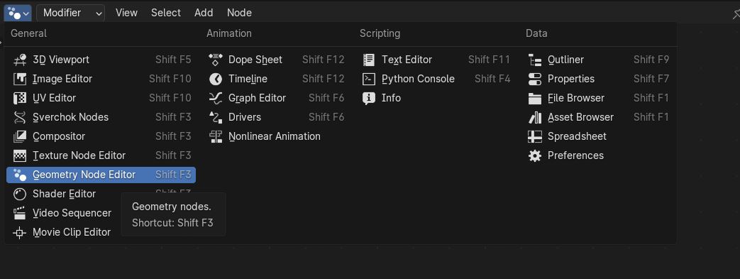
- Change a window to become a Geometry Node editor window…by clicking the icon on the upper left corner of a window…
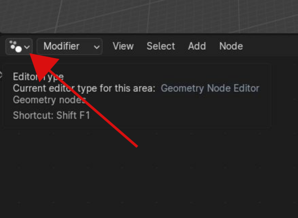
…then choosing Geometry Node Editor
- Select the default cube (yellow outline) in the 3D Viewport window…click ”+ New” in the Geometry Node Editor window
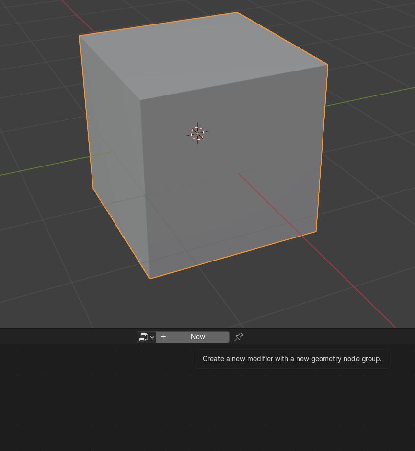
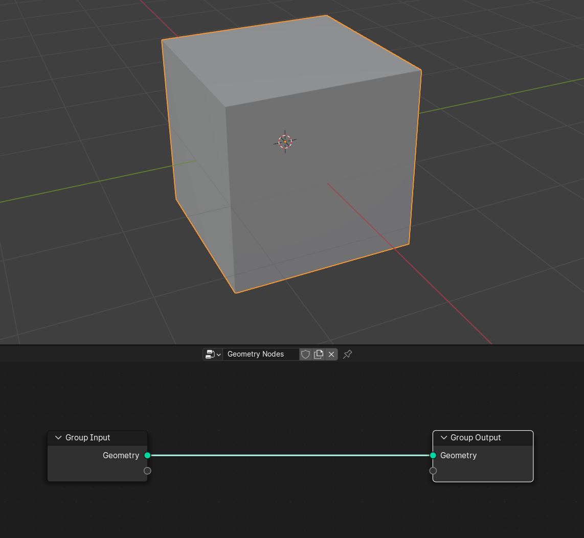
OK! Now we are ready to build a new Geometry Node Tree!!
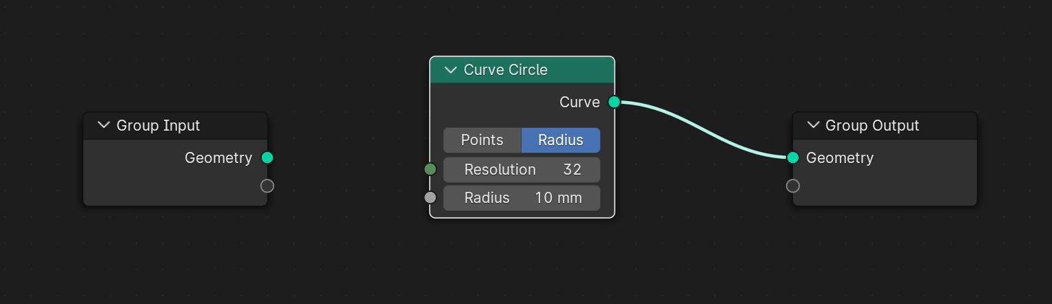
Step 1 > Adding a Curve Circle
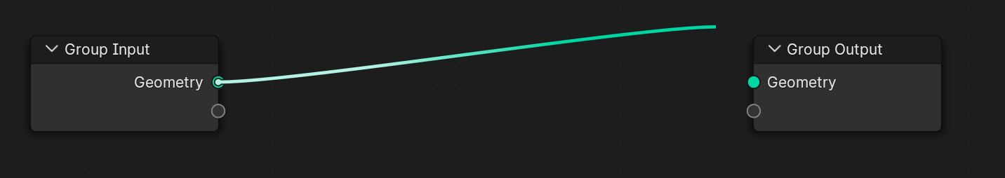
- In the Geometry Node window…
- Disconnect the Group Input node from the Group Output node (left click on one of the connection socket and disconnect the green line).
- SHIFT + A…to add nodes
- …add a Curve Circle node
This will be our Base Geometry to be modified by parameters and slot cuts
Creating Parameters
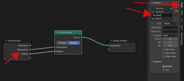
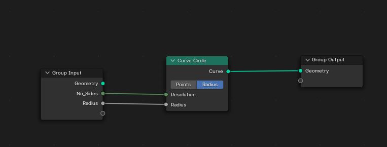
- …connect the Curve Circle’s Resolution and Radius input nodes to empty connection sockets (below the “Geometry” socket) in the Group Input node.
- …rename the connection sockets in the Group Input node from “Resolution” to “No_Sides” by typing N in the Geometry Node window to open the pop-up menu on the right side. Click the Group tab and type “No_sides” in the ” ” input window.
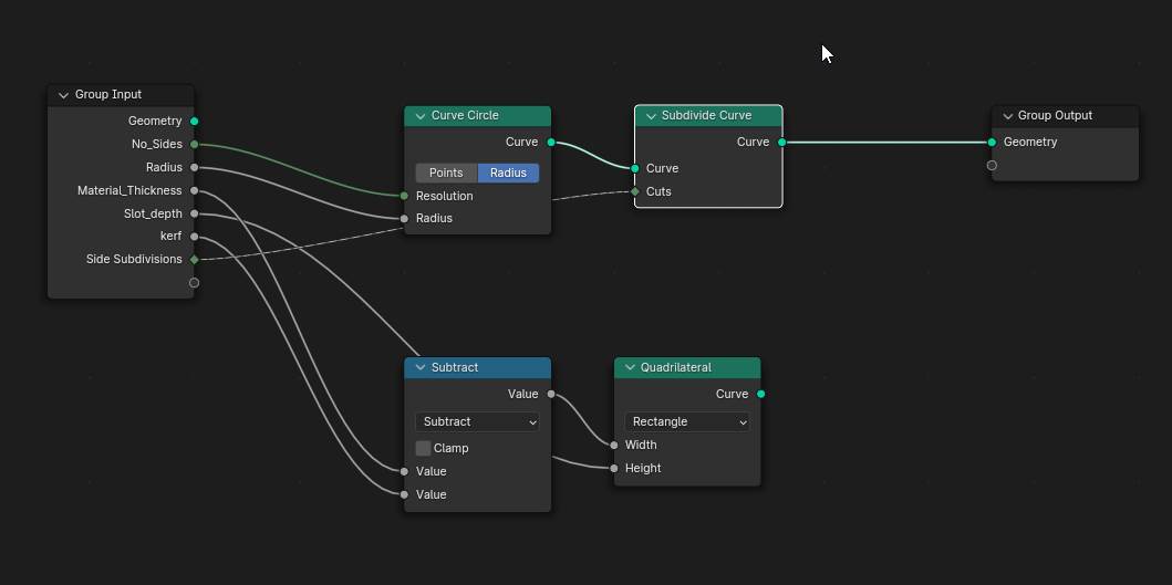
Step 2 > Creating the Press-Fit Slot Geometry
We will add a Quadrilateral (basically a rectangle) which will be used to cut Press-Fit Slots into the Base Geometry.
- Add a Quadrilateral node and a Math node.
- Select Subtract as the math operation from the drop-down menu in the Math node.
- Connect the Value output socket of the Subtract/Math node to the Width input socket of the Quadrilateral node.
- Connect the Height input socket of the Quadrilateral node to an empty socket of the Group Input node…rename it Slot_Depth.
- Connect the topmost input value socket of the Subtract/Math node to an empty socket of the Group Input node to make it a parameter…rename it Material_Thickness
- Connect the bottommost input value of the Subtract/Math node to an empty socket of the Group Input node…rename it Kerf.
- Add a Subdivide Curve node and attach its curve input socket to the curve output socket of the Curve Circle node.
- Connect the input Cuts socket of the Subdivide Curve node to an empty socket of the Group Input node…rename it side Subdivisions.
The subdivision location of the Base Geometery will become the locations of the Press-fit Slots.
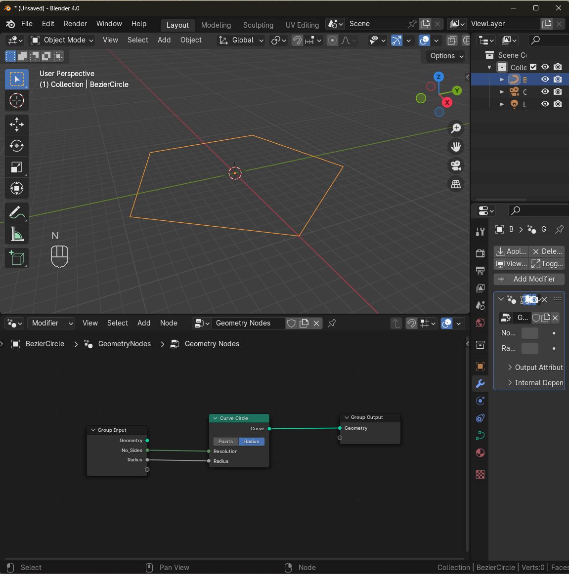
Set the Primary Parameters
By connecting node sockets to the Group Input nodes, we create adjustable parameters in the Geometry Node Modifier properties (lower right side of the screen…the blue wrench icon).

Parameters that can be adjusted include…
- Number of Sides for the Base Geometry
- The Radius width of the Base Geometry
- The Material Thickness dimension that will define the slot width
- The Slot Depth
- The lasercutter’s Kerf
- The Side Subdivisions
Set these parameters to your liking.
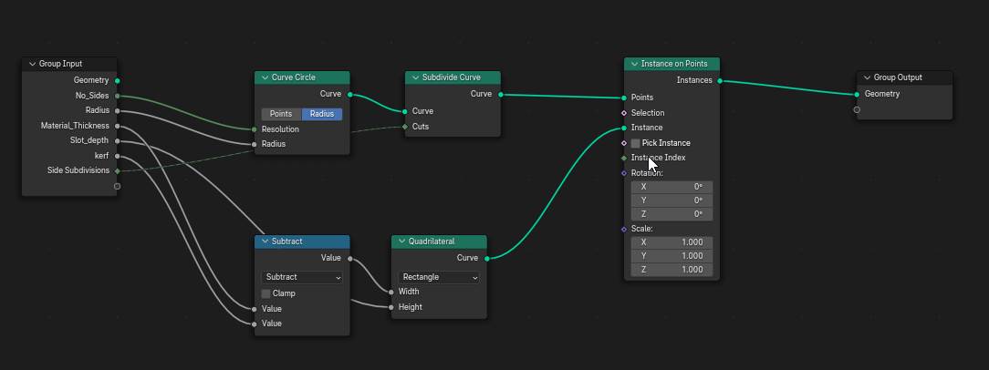
Instancing the Slot Geometry to the Base Geometry
Now that we have the Base Geometry with subdivided sides, it is time to instance (duplicate and place) the Slot Geometry onto the sides of the Base Geometry at the subdivision locations.
- Add an Instance on Points node
- Connect the Curve output socket of the Subdivide Curve node to the Points input node of Instance on Points node
- Connect the Curve output socket of the Quadrilateral node to the Instance input node of Instance on Points node
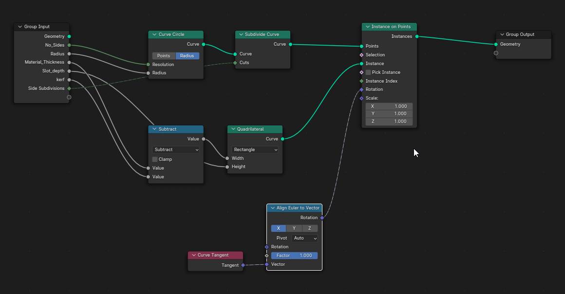
- Add an Align Euler to Vector node and a Curve Tangent node. These nodes will allow us to rotate the Slot Geometry to its correct perpendicular position on the sides of the Base Geometry
- Connect the Rotation output socket to the Rotation input socket of the Instance on Points node
To see what we have made so far, we will temporary…
- Add a Join Geometry node…place it after the Instance on Points node
- Connect the Instances output socket of the Instance on Points node to the Geometry input socket of the Join Geometry node
- Connect the Curve output socket of the Curve Circle node to the Geometry input socket of the Join Geometry node
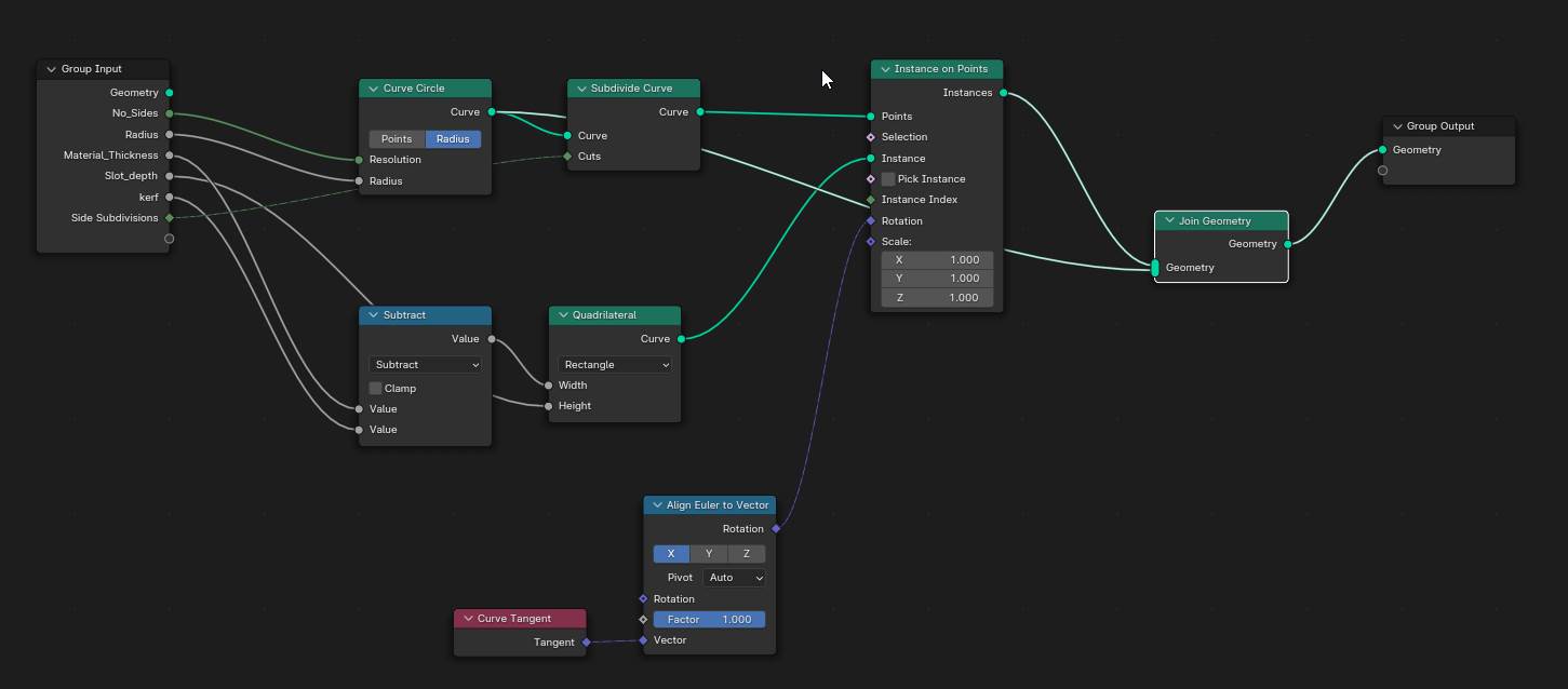
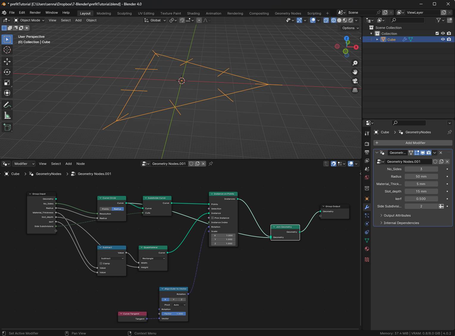
…and you should see a skeletal preview of what we have made so far. Play with parameters and see how things change. Don’t mind that it looks a little weird at this point…we skill have more nodes to add!
Tip: If you want to see what a node does…select it and press M to mute and unmute its effect!
Refining the Press-Fit Part Base Geometry
Now that we had a preview of the geometry, let’s…
- Delete the Join Geometry node (select it and click X).
- Add the Fillet Curve, Fill Curve and Mesh Boolean nodes
- Connect the Curve output socket of the Curve Circle node to the Curve input socket of the Fillet Curve node
- Toggle the Poly option for the Fillet Curve node…and set the Count to about 5
- Connect the Radius input socket of the Fillet Curve node to an empty socket of the Group Input node to make it a parameter…rename it Corner Radius. Set the Corner Radius to something you like.
- Connect the Curve output socket of the Fillet Curve node and connect it to the Curve input socket of the Fill Curve node
- Toggle the N-gon option of the Fill Curve node
- Connect the Curve output socket of the Fill Curve node and connect it to the Mesh 1 input socket of the Mesh Boolean node
- Set the Mesh Boolean operation to Difference (since we want to cut holes in the Base Geometry with our Slot Geometry)
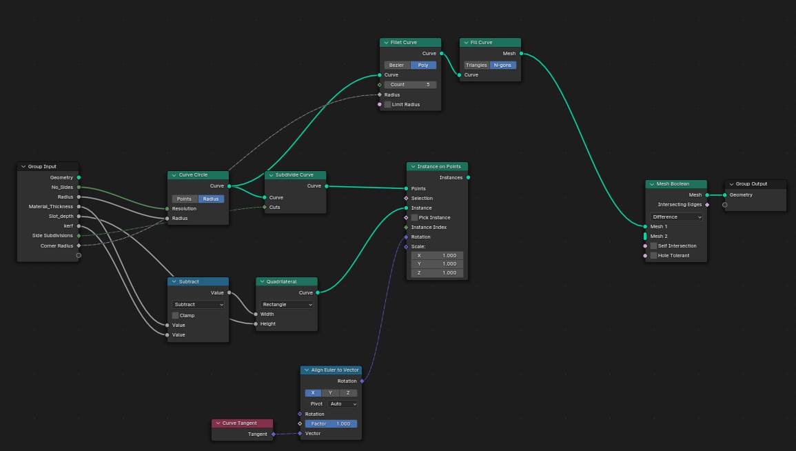
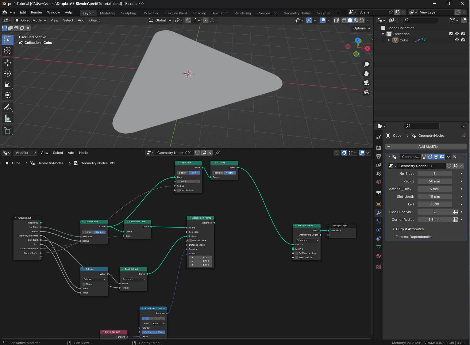
Our Base Geometry now has a nice shape with round corners!
Organizing the Node Tree with Frames
The node tree can get a bit confusing after many nodes have been added. It is helpful when related nodes are grouped together to make later modifications a bit easier.
- Add Frames and you will see a small black rectangle
- By selecting a number of related nodes (hold down the SHIFT key as you select them) and then dragging them into the empty black Frame rectangle…you will create a moveable group of nodes within the node tree
- The Frames can be given labels by typing N in the Geometry Node Editor window to toggle open the side menu…then in the Node tab you can enter a name in the Label text input cell
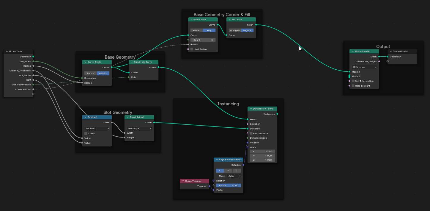
Here are my framed groupings…
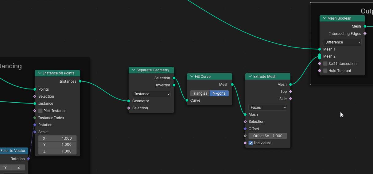
Adjusting the Instanced Slot Geometry
The next few nodes added will adjust the appearance of the Slot Geometry which will then be added into the Mesh Boolean node as the cutting or Difference geometry at the Mesh 2 input socket
- Add the Separate Geometry, Fill Curve, Extrude Mesh nodes
- Set the type option of the Separate Geometry to Instance
- Connect the Geometry input socket of the Separate Geometry node to the Instances output socket of the Instance on Points node
- Connect the Selection output socket of the Separate Geometry node to the Curve input socket of the Fill Curve node
- Toggle the N-gons node of the Fill Curve node
- Connect the Mesh output socket of the Fill Curve node to the Mesh input socket of the Extrude Mesh node
- Set the mesh selection type to Faces
- Connect the Mesh output socket of the Extrude Mesh node to the Mesh 2 input socket of the Mesh Boolean node
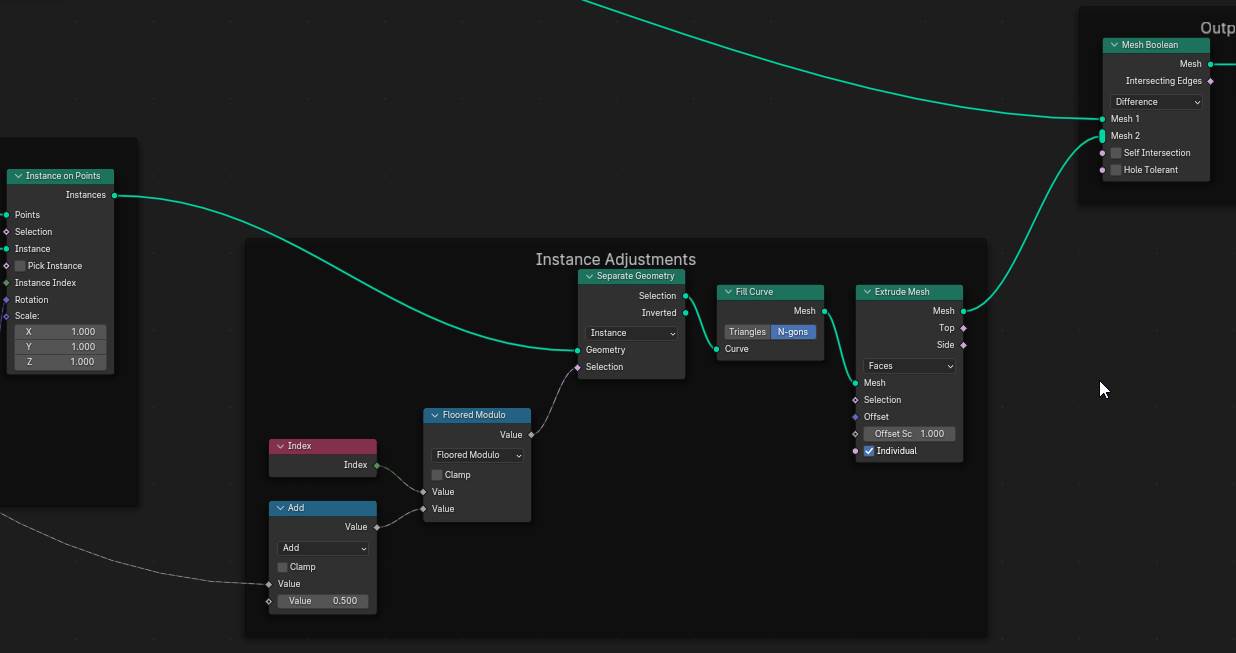
Not done yet! A couple more nodes to add…
- Add 2 Math and an Index node
- Set the operation for one Math node to Add
- Set the operation for the other Math node to Floored Modulo (Returns the positive remainder of a division operation)
- Connect the Index output socket of the Index node to the top Value input socket of the Floored Modulo node
The Index node provides the sequential number associated with each of the Slot Geometry instance
- Connect the bottom Value input socket node of the Floored Modulo node to the Value output socket of the Add node
- Connect the Value output socket of the Floored Modulo node to the Selection input socket of the Separate Geometry node
- Connect the top Value input socket node of the Add node to the Side Subdivisions socket of the Group Input node
- Input the number 1 into the bottom Value cell of the Add node
I will drop a frame to group all these new nodes…
Oops!! I made a mistake!!
Early on, from the Quadrilateral node I connected the Width input socket to the Material Thickness socket…and the Height input socket to the Slot Depth socket…of the Group Input node. It should be the opposite.
Width is the Slot Depth of the Slot Geometry while Height is the Material Thickness (I renamed the parameter to “Slot Wide”).
Here is an image of the corrected connections…
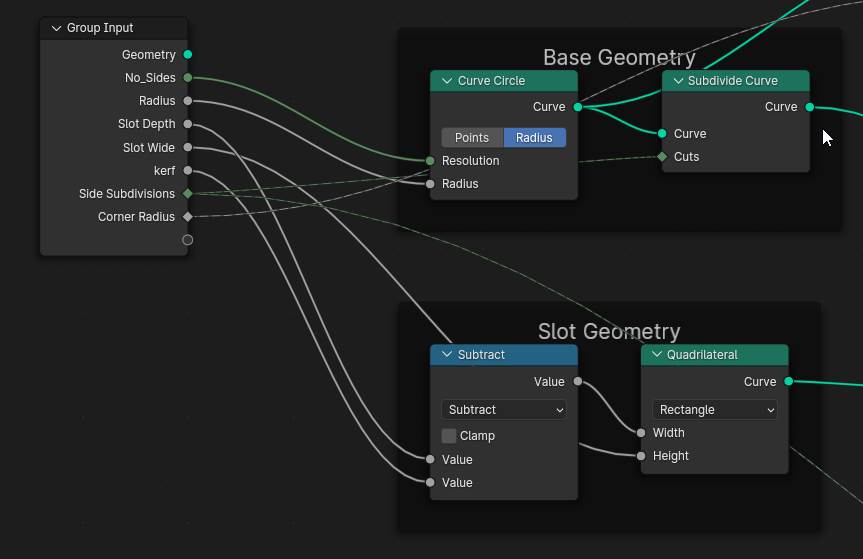
After making this correction, we can see a great preview of our Press-Fit Part with the Slot Geometry carving slots out of it at the subdivision points specified at the beginning. Hooray!!
The Final Touches > Add Fillets
Now we will add a few final nodes into the Output group of nodes…in between the Mesh Boolean node and the Group Output node. These last nodes will add fillets to our geometry.
- Add the Mesh to Curve, Fillet Curve and Fill Curve nodes
I won’t even bother to describe the process this time…the connections are so easy. Here is an image to refer to…
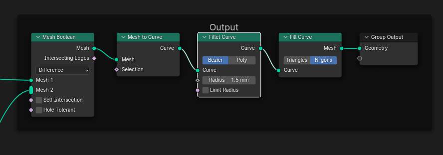
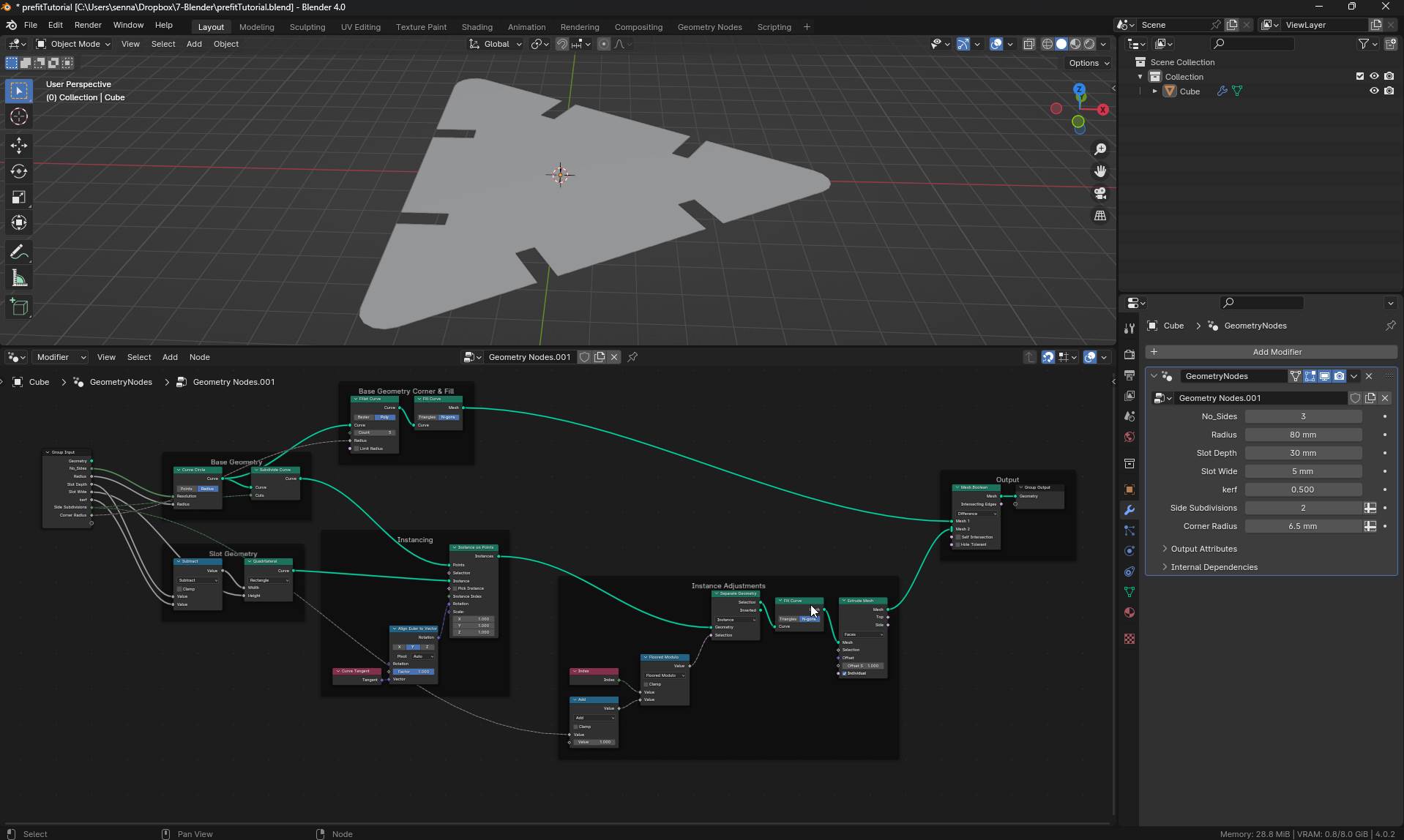
That’s it!!! All done
The Parametric Press-Fit Part in Blender
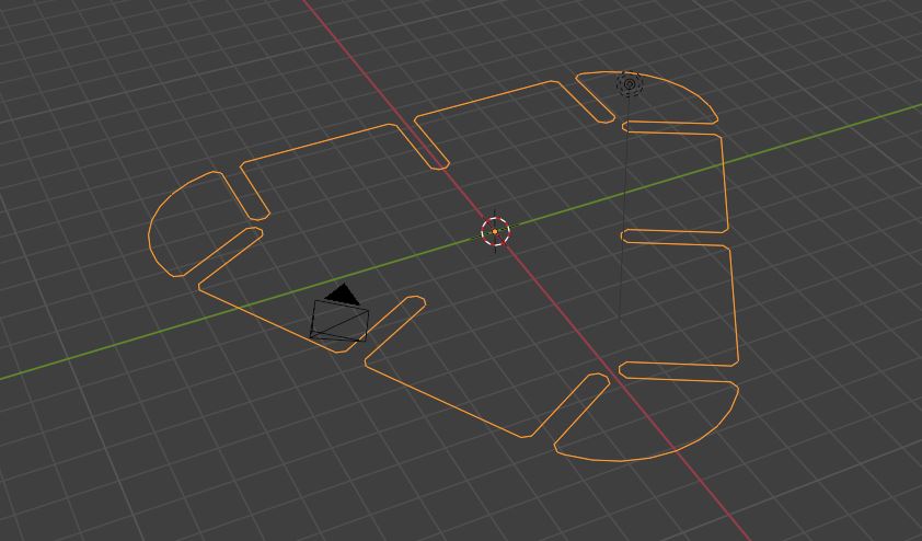
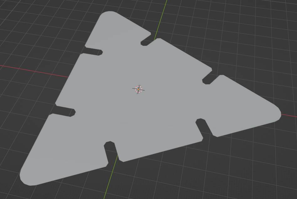
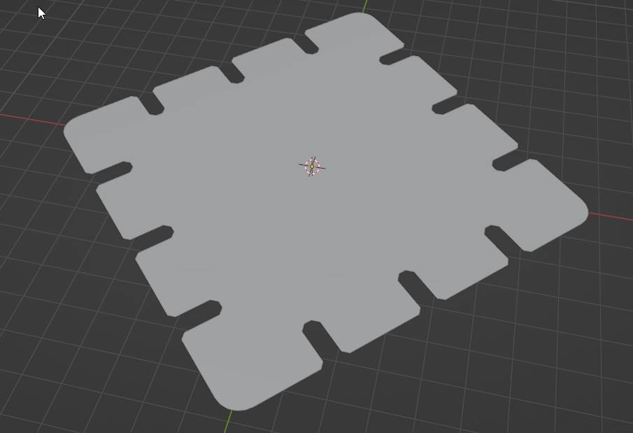
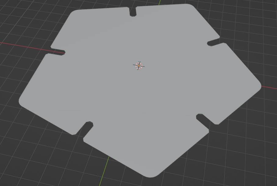
Here are some sample images of parts created with the model…
3-Sided with 2 Slots per side
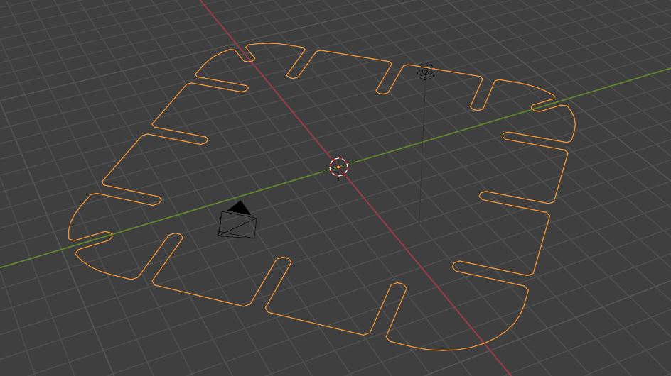
4-Sided with 2 Slots per side
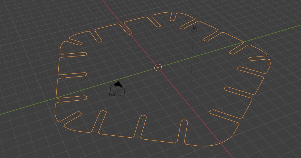
5-Sided with 1 Slots per side
And here is the Blender File for you to play with!
And here is a link to Luis Pancheco page where he shows how to use a script to generate gcode from the Geometry Node shapes