Week 04: Electronic Production
This Week’s Task
Group Assignment:
- characterize the design rules for your in-house PCB production process
- send a PCB out to a board house
Fab Lab Bali’s PCB Production Process
This week’s group assignment is to characterise the design rules for Fab Lab Bali’s in-house PCB production. In Fab Lab Bali, we have 3 PCB Milling Machine.
- Sainsmart Genmitsu 3018-PRO CNC Router DIY Kit
- Sainsmart Genmitsu 3018-PROVer V2
- Modela MDX20
For this documentation We will be focusing on the PCB design rules for the Sainsmart Genmitsu 3018 machines.
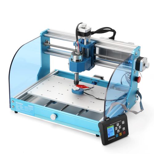
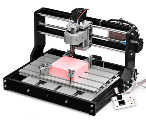
Setting Up the 3018 CNC Router Machine
–
Bed Leveling
Ideally you would want to level your PCB board by having a sacrificial board underneath it because when milling a PCB, the slightest variation in height across your copper board can affect your isolation milling traces. Having a flat sacrificial board will insure your PCB board is level and flat relative to the spindle. Moreover, the sacrificial board will become a protective layer so that you don’t ruin the alumimium board of the machine.
You would want to level your flat sacrificial board with a Spoilboard Surfacing end-mill.It looks like this.
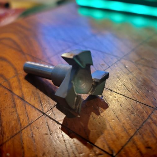
Unfortunately, that particular bit is not on sale in Bali. So we decided to 3D-Print the following jigs to hold the PCB board.
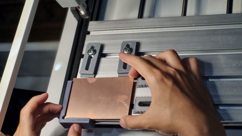
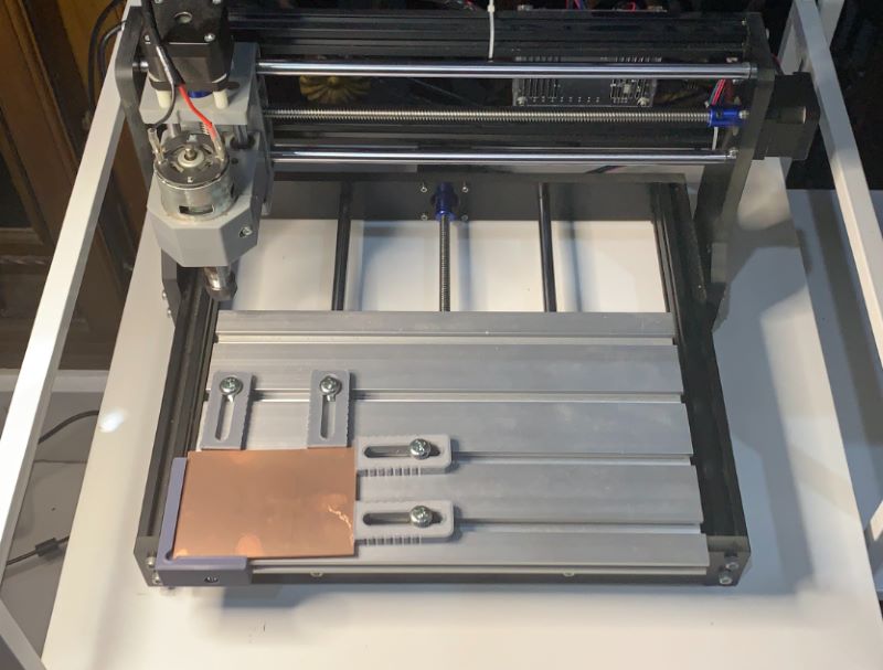
You can find the the OpenSource STL file here
Set Endmill into Spindle
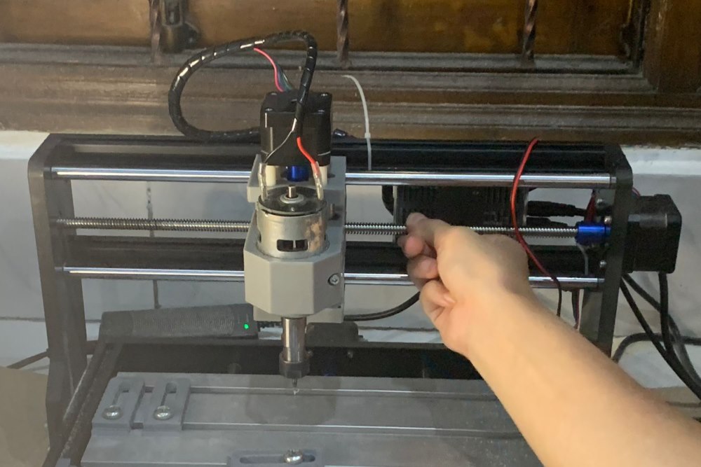
First you want to make sure that the spindle is straight. So that when you insert the endmill, it is calibrated straight. Insert the Endmill bit, make sure that it’s inserted halfway through the length of the bit. Tighten the spindle to hold the endmill in place.
Setting X,Y
The machine comes installed with a GRBL Firmware for control. There are multiple softwares that can channel GRBL to control the 3018 machine but for this week, we used Candle.
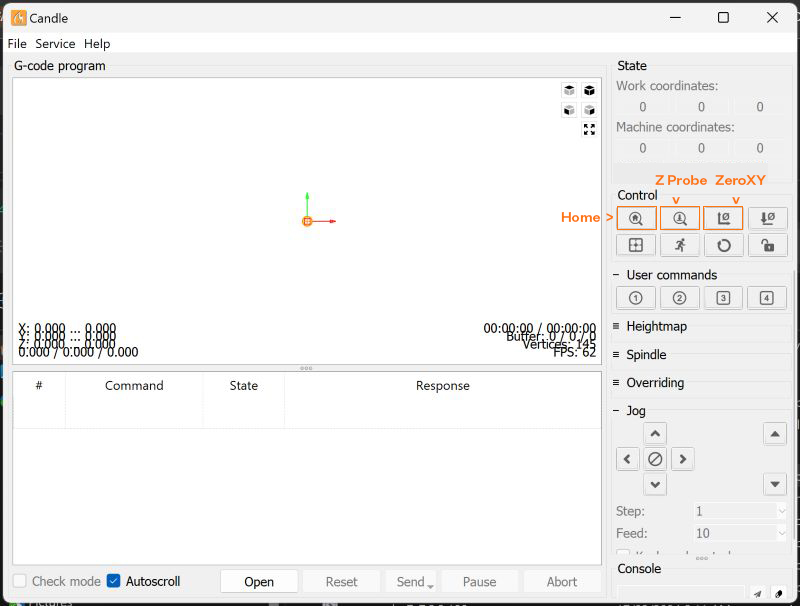
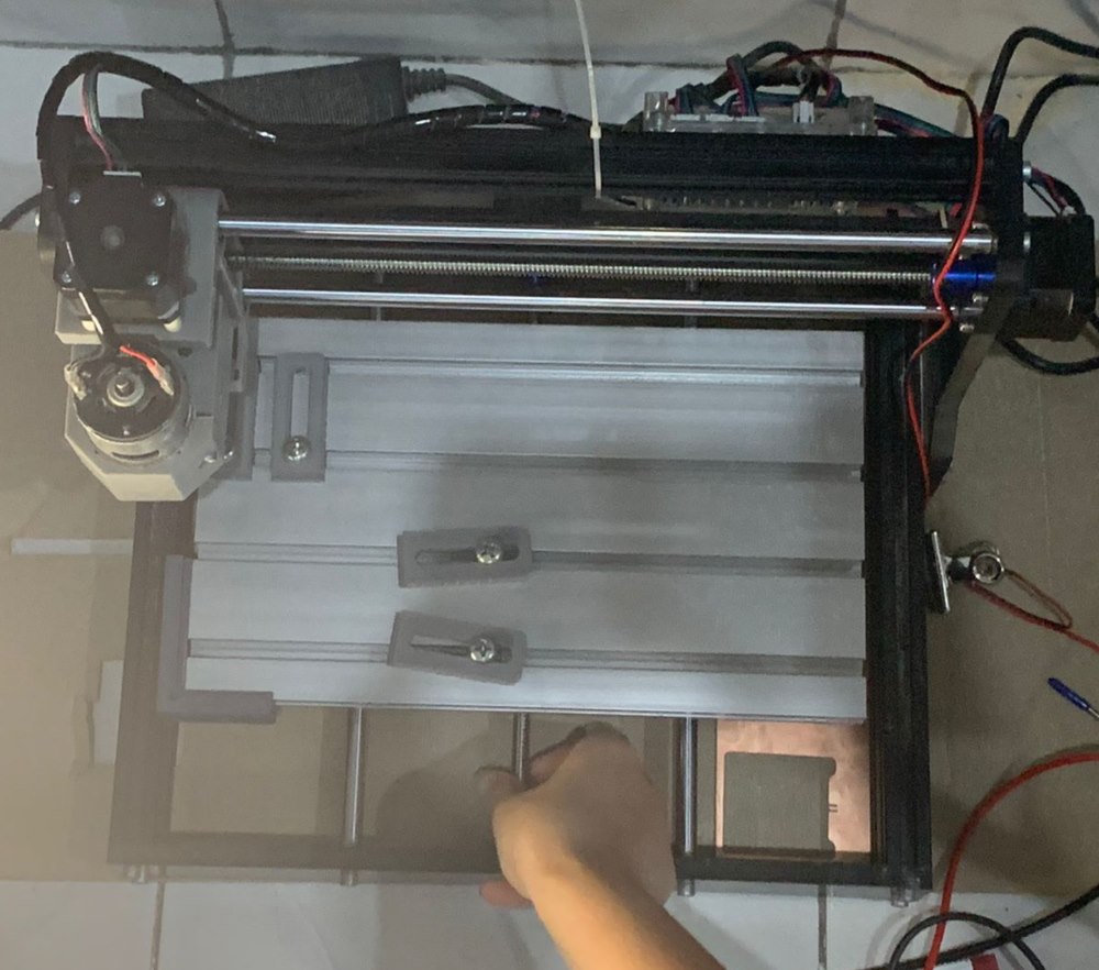
The PROVer V2 has a limit switch so in Candle you can press the Home Button. The DIY machine on the other hand does not so to get to home you will have to manually twist the lead screws (x,y) axis till you no longer can to get for (0,0).
In Candle press ZeroXY to ensure the firmare of your (0,0) coordinate.
Height Probing
With the CNC 3018 you can probe your height with the given prober. More information you can check here
 .
.
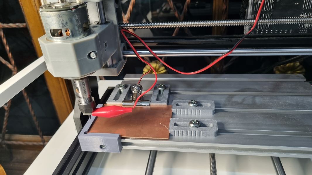
When you Z-Probe, the height will go down and once it hits the probe, it will go up. Before running the job, it’s advisable to check for Z-Probe. You can also utilise Z-Probe to do height-mapping. Since the copperboard may not exactly be ‘completely’ level, height-mapping is important so that the machine can run the job precisely. Follow the tutorial here
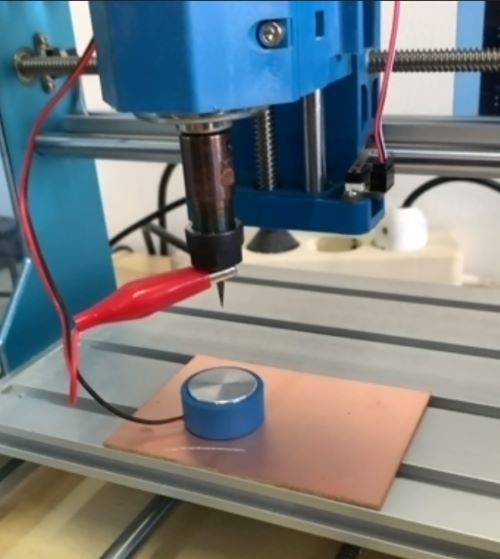
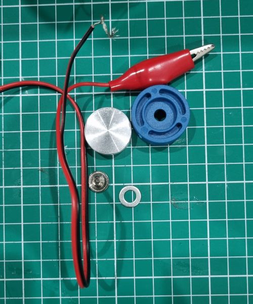
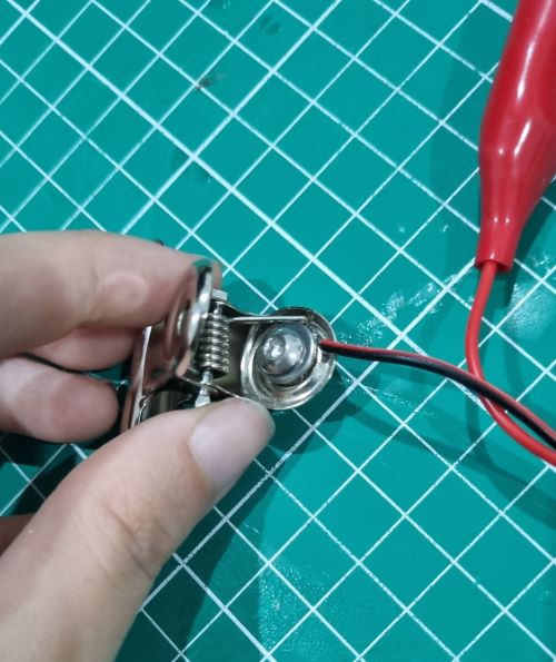
To customise your probe, unscrew the probe, and coil the black wire onto an paper clip (we suggest using a bolt and screw to tighten it). Check for continuity with the multimeter. Then clip the alligator clip onto the endmill and the paper clip onto the copperboard
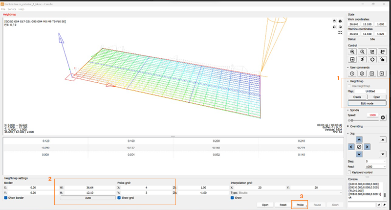
Insert your file to be traced/cut and run the heightmapping function (1). Set the job size and the grid for your heightmapping (2) and hit the probe button (3). Watch the magic happen.
Design Parameter
–
-
Tool diameter (in)
-
Cut Depth (in): How deep the milling tool should cut in a single pass. General Rule of Thumb for Depth of Cut = 1/2 Diameter of your Endmill.
📝 E.g if your bit is 1/64”, you shouldn’t be cutting deeper than ~0.07mm.
But the idea is to find a sweet spot where the tool would not have to go too deep that it would degrade, or worse, break, the endmill easily, but not too shallow that it would take forever to cut.
-
Max Depth (in): The total maximum depth of cut you want to do in a single milling operation. This setting will result in how much vertical passes needed to be performed by the milling tool.
📝 Example: You have 1mm thick material and you plan to cut it all the way through. If you set your depth per pass to 1mm it will take one pass to cut it out. That is not advisable for most ‘hard’ material as it produces too much strain on the end-mill bit. If you set your depth per pass to 0.5mm then it would take 2 passes to make the cut all the way through but you can get better results.
It is advisable to be conservative with your setting but your production process will be slower.
-
Offset Number: This refers to the number of passes that the milling tool makes over the PCB surface (horizontally) to complete the milling process. After several trials and errors, we understand that higher offset number can significantly increase the milling time, and excessive tool wear may occur if too many passes are made.
-
Offset Stepover: We didn’t really explore this one at first, but towards the end, we found out that this refers to the distance between each pass of the milling tool as it moves across the surface of the PCB. It will determine how much material is removed with each pass, and typically specified as a percentage of the tool diameter. This basically serves like the kerf rate in laser cutting
-
tab width (in) and tab length (in): these two features are used to set dimension if you want to add tabs to your PCB so that it stays afloat at the jig.
-
Feed Rate: refers to the lateral motion (xy axis) speed, the rate at which your end-mill advances along carve your project. The lower the speed the finer the cut result, in the expense of longer the duration.
-
Plunge rate vertical motion speed - the feed rate but applied to your Z axis. How fast your bit lowers down into your material before beginning X and Y movement to cut
-
(Spindle) Speed controls the rotational speed of the spindle that holds the milling tool. Higher spindle speeds are typically used for cutting softer materials or achieving finer surface finishes, while lower spindle speeds are used for harder materials or heavier cutting operations.
PCB Milling Workflow
Here is the general workflow if you want to mill your own PCB:
- Prepare PCB design files (in vector)
- Transfer vector image into GCODE file to be sent to the machine. Here we’re using MODS
- Load GCODE into machine control software (GRBL). Here’ we’re using Candle
- Perform
- Mill
Transfering PCB vector image into GCODE file using MODS
Mods is a modular cross platform tool intended for use with commonly found machinery in fab labs. It is based on independent but interrelated modules and can be used in various tasks, including CAD, CAM, machine control, automation, UI development, input device integration, and responsiveness to physical models.
Here’s the step by step tutorial of how to generate GCODE file for PCB milling with MODS
🖍️Note: the following workflow is for the context of using Sainsmart milling machine, which currently does not have a dedicated program in mods, unlike the Roland Modella machine.
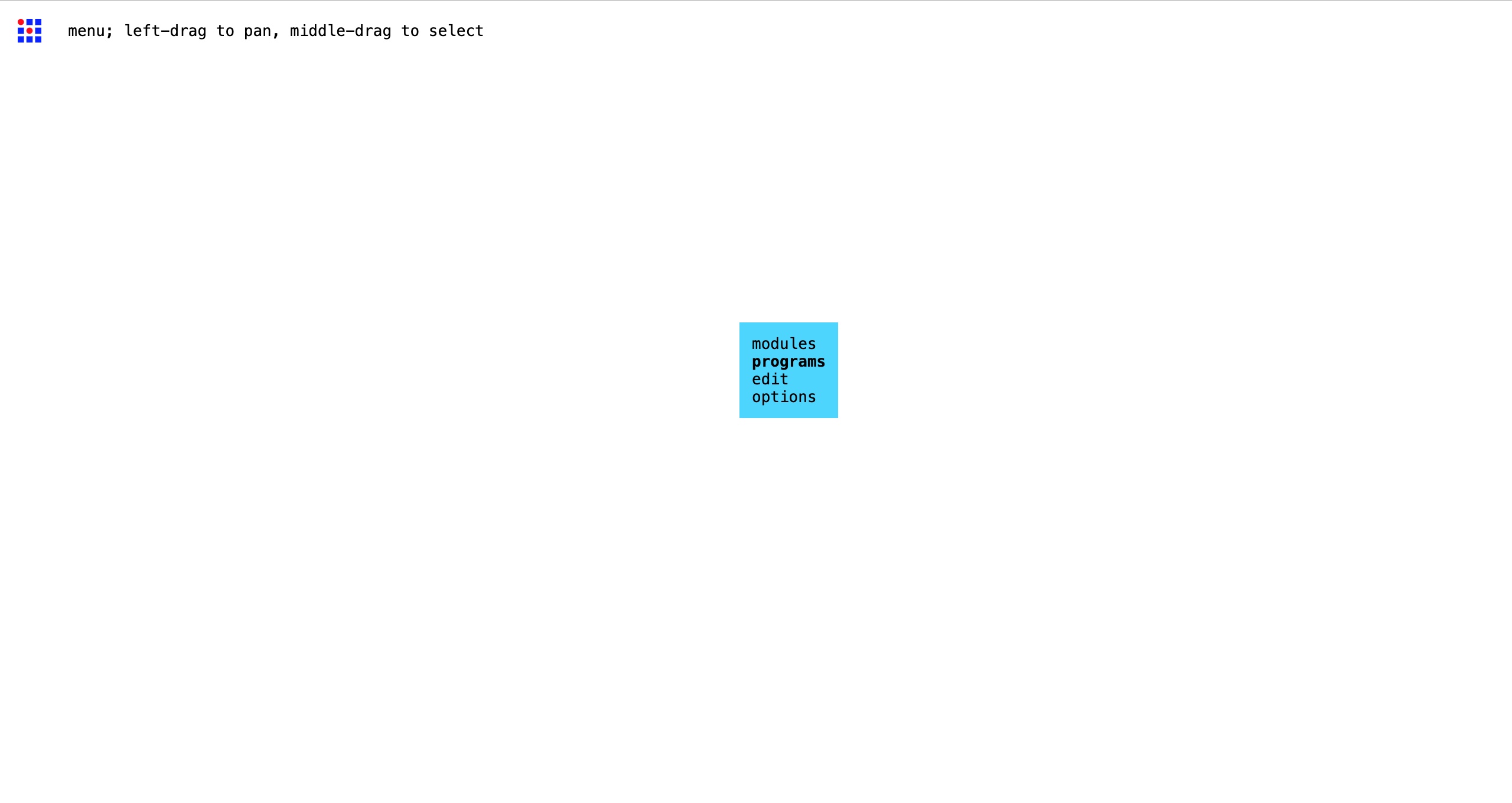
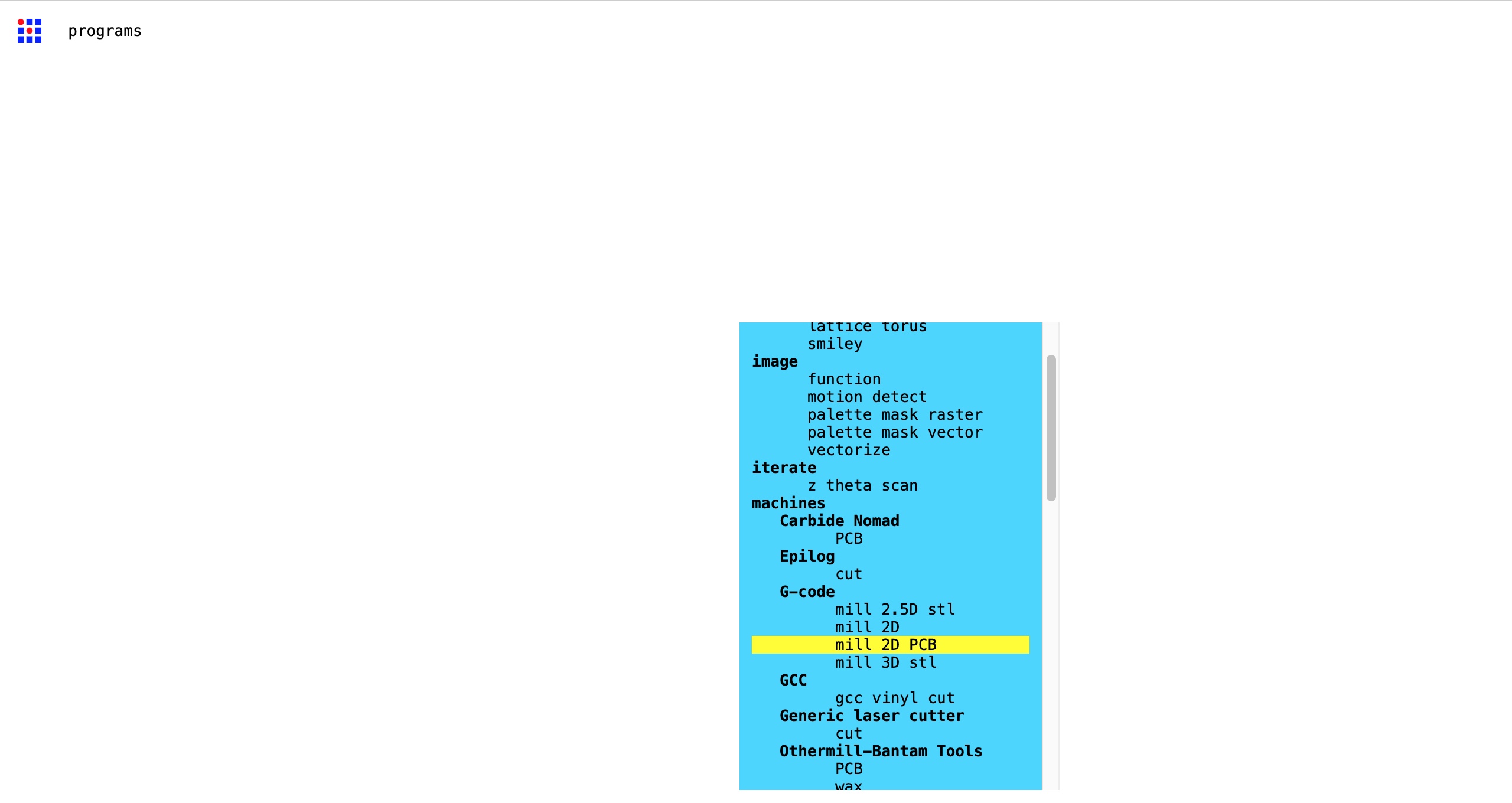
- Go to Mods: modsproject.org
-
Right click anywhere on the screen. Choose Programs > Open Program > G-code > ‘mill 2D PCB’
-
You will be directed to this node tree. Here, there are 4 nodes that you will use a lot and hence should be focusing on.
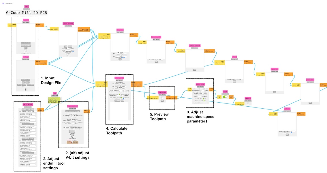
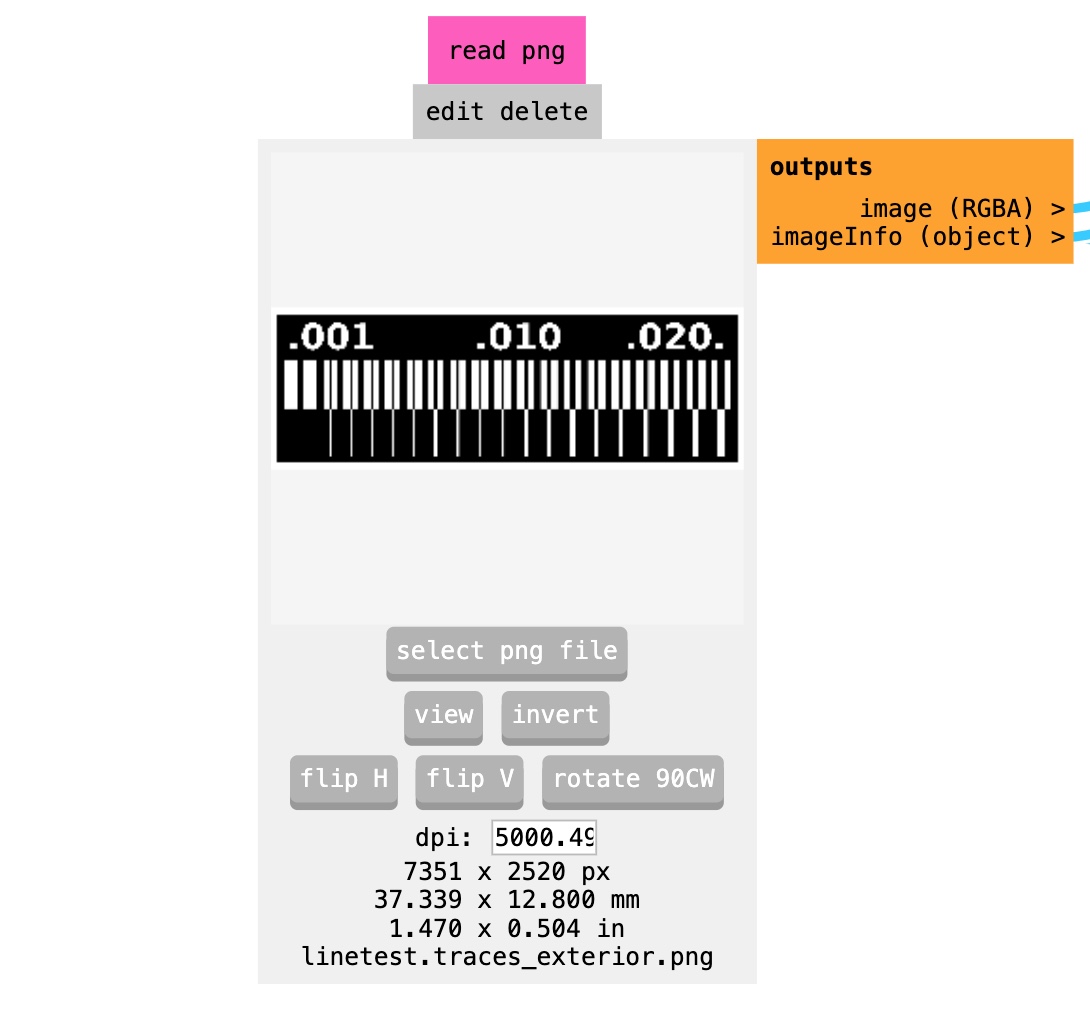
-
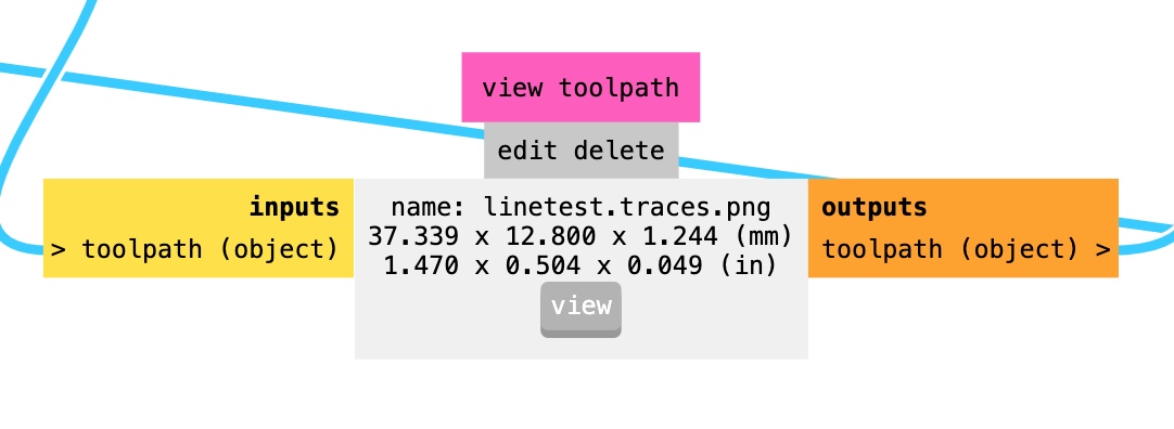
First, direct to ‘Read SVG’/’Read PNG’ node to input your file
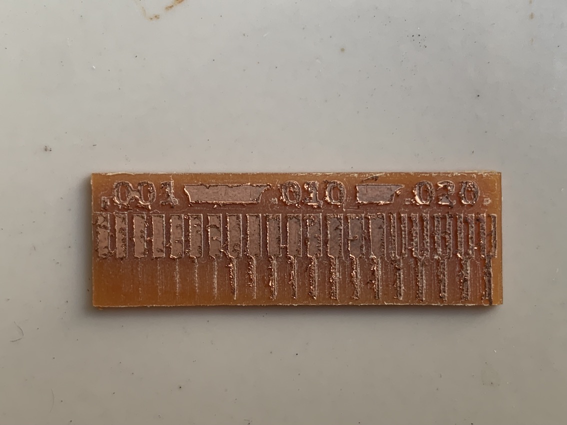
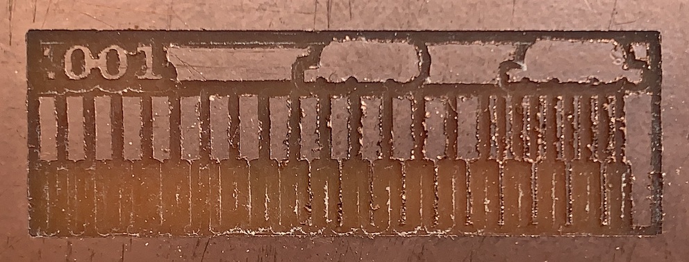
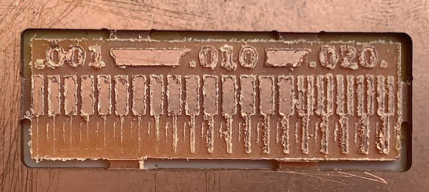
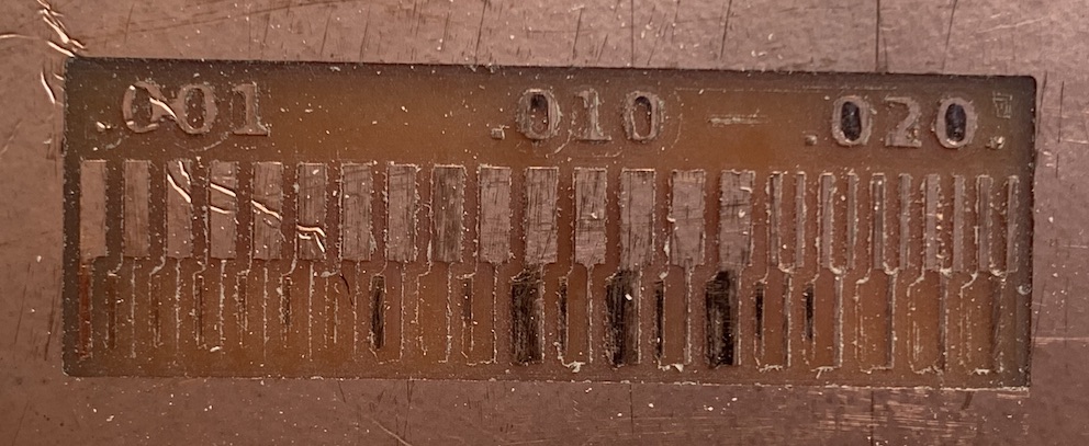
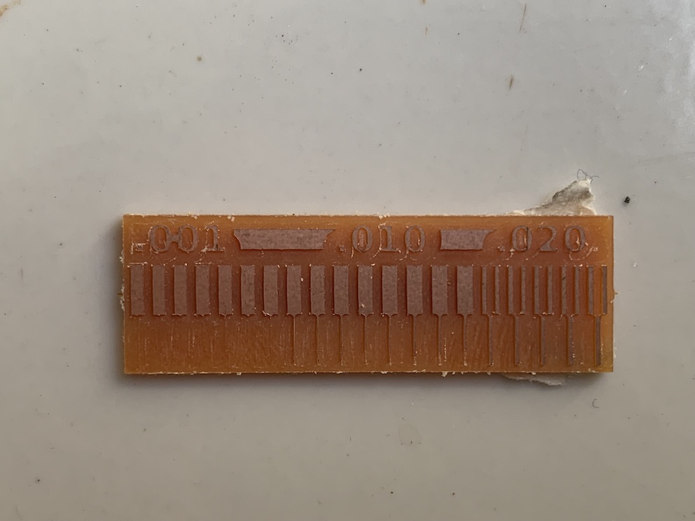
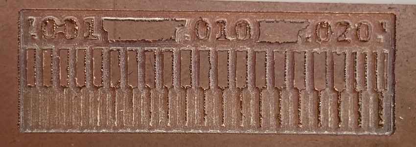
To upload your file, just click ‘Select PNG File’ and choose your image file. Once loaded, the node will show you the file information, like resolution, dimension, etc, and the overall tree will start processing your image. For the characterization we use the provided png file here: Trace only, Trace with Exterior, Outline Cut
-
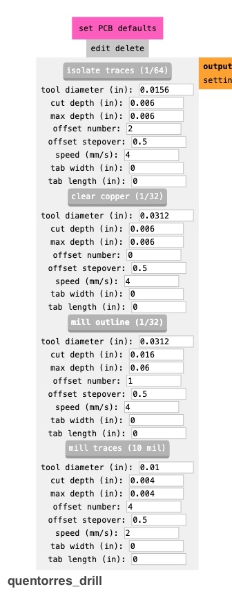
Second, ‘Set PCB Defaults’ node or ‘V-bit Calculator’ to adjust your milling tool settings
This node is where you will input the information of your milling tool (endmill) and regulate how it should behave in milling operation. Generally, there are two types of milling operation to produce your PCB: Trace and Outline cut. For each of the milling type, you might need different milling tool, hence different settings.
By default, mods has provided us with 4 default presets for 4 different typical endmill sizes. Typically, people use the 1/64 inch (0.4 mm) endmill for tracing and 1/32 inch (0.8 mm) endmill for outline cutting. But in the end, we decided to go with the V-bit for tracing. In terms of the settings, this is what works best for us by far.
Context: Our PCB board thickness is around 1,3 - 1,4 mm
-
Tracing with 1/64 endmill
Choose the ‘Isolate Traces (1/64)’ label and input these settings:
💡 Since in tracing we just need to remove the copper layer of the PCB, which is around 0.1 mm thickness, that’s why we set the cut and max depth to 0.1 mm.
💡 In order to accelerate the milling process, we lower our offset number to 2, so it will mill the line with only 2 passes (previously we always set 4). This cut the job duration by at least half.
💡 We set the speed to 4 based on our desk research. Here, it’s mentioned that the recommended speed is 3 or 4 for new endmills. We assumed our endmill is new and we strive for a faster milling process. Besides, we will determine the speed again in the next node and also later can be adjusted again in the candle controlling software.
-
Tracing with V-bit
We prefer V-bit because it’s widely available and easier to access here in Indonesia and much cheaper price-wise. But since V-bit shape is different than endmill, V-bit has a V-shaped end tip meanwhile endmill has a straight shaped end tip, we need to calculate the tool diameter or cut width relative to the cut depth of the V-bit.
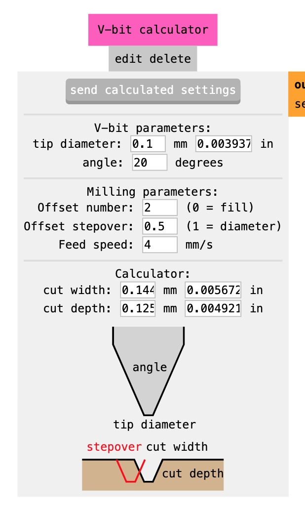
Apparently, Mods has provided us with an alternative node to use V-bit. To do that,
Context: we use a 0.1mm tip with 20 degree angle V-bit
- go to ‘V-Bit Calculator’ and input the dimension of your v-bit and intended offset value. It will automatically adjust the cut width and depth.
-
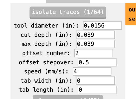
Alternatively, we can still use the ‘Isolate Traces (1/64)’ label, but we need to calculate manually and input the settings
💡 You can use any trigonometry calculating tool, but we use Fusion360 to calculate ours. Our starting reference point is the copper layer thicknes of the PCB, which is 0.1 mm, as the cut-depth. But, we don’t know if the V-bit we have is new or has been used before. So, assuming that it’s been used before, thus the tip’s a bit degraded, we add our cut depth to 0.125 mm (0,049 inch), which result in cut width around 0.144 mm
💡 We also enlarge our tool diameter size by around 0.5 mm, to offset the centre of the tool a bit away from the line edges, in order to maintain the line thickness. Or, we later found out that we can just change the Offset Stepover value to do this, instead of editing the tool diameter.
In the end this is how our overall V-bit setting looks like from the Set PCB Defaults node:
-
Cutting and Drilling with 1/32 endmill
Choose the ‘Outline Mill (1/32)’ label and input these settings:
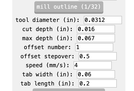
💡 Our PCB thickness is around 1,3 - 1,4 mm, but the reason we set the max. depth to 1.7 mm is because of the fact that the jig we use leave some gaps underneath, makes the PCB board afloat, thus during the cutting process, it will bend downward a little bit. So, we have to account for this bending allowance.
💡 Also because of jig making our PCB floating, we need to add tabs in the outline to hold the board so that it would not fall when the cutting process reach towards the end.
Once you’re done with the your milling tool settings, don’t forget to click the title label button! This will send the setting info to the next node.
-
-
Next, go to ‘Path to G-Code’ node to adjust your machine operation parameters
This node is where we will control the instructions that tell the milling machine on how to move the milling tool. Here are the main parameters to be adjusted in this node:
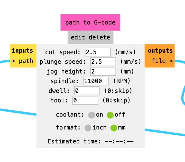
Cut Speed is basically the Feed Rate in mods. The idea is to find the sweet spot to not only optimize the milling process but also preserve the milling tool: fast milling, fine result, longer milling tool shelf life. Here are the settings that works best for us by far:
-
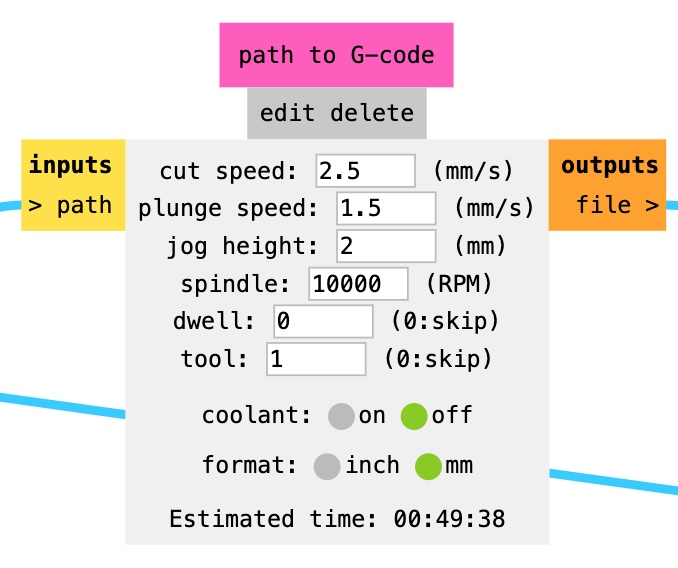
Machine Settings for Tracing
Set the ‘Tool’ to 1 (Yes)
-
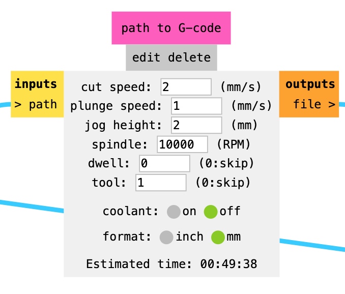
Machine Settings for Outline Cutting or Drilling
Set the ‘Tool’ to 1 (Yes)
💡 The maximum RPM for this type of Sainsmart machine is 10.000 RPM. We tried with 8000 RPM, but the result is coarser finish.
-
-
Finally, direct to the ‘Mill Traces’ node to calculate toolpath
This node will derive and combine all the information from the Set PCB Defaults and the Path to G-Code nodes to calculate the predicted toolpath and generate the G-Code file.
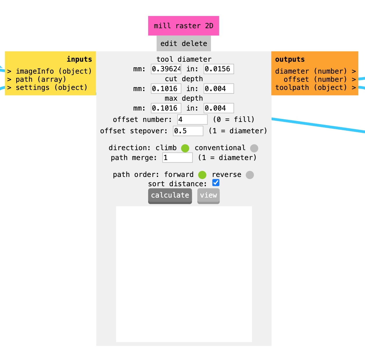
💡 Make sure the details shown here are sync with what you’ve put on the Set PCB Default node! If not, go back to that node and click on the endmill selection label once more.
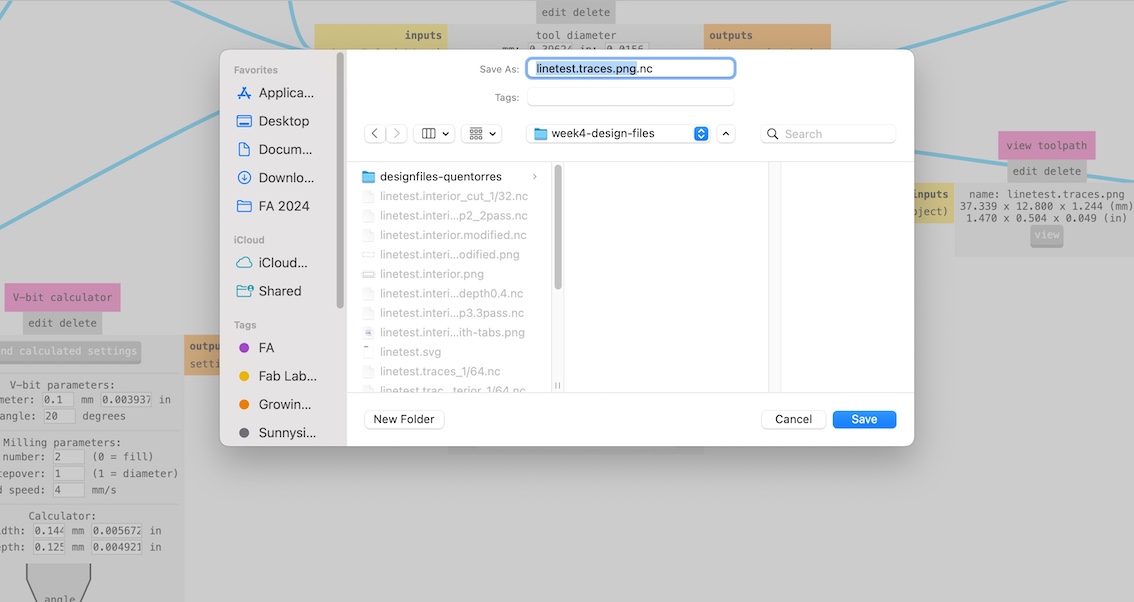
If all is well, go ahead and click ‘Calculate’. Once the calculating process is done, it will automatically save your G-Code file in .nc format and generate preview of the toolpath.
-
Not finished, yet! Examine the generated toolpath!
Examining the toolpath is very important to help us identify potential errors or issues in the machining process before actual fabrication begins. It helps us verify that all traces, holes, and other features are correctly translated into toolpaths and will be milled according to specifications. We can do this alternatively by going to this node and click ‘View’.
The blue color represent the cutting movement, the red color represent the non-cutting movement.
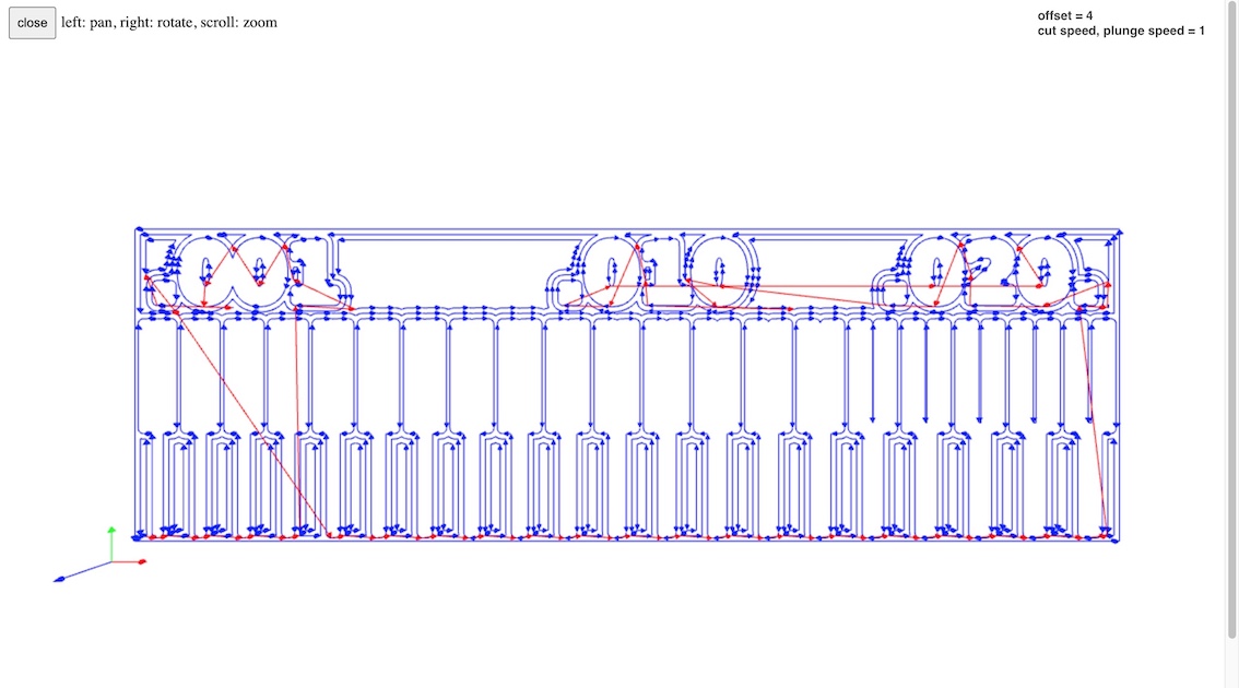
If all is well with the toolpath, you go ahead and send the file to the machine control software!
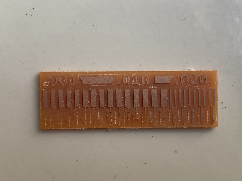
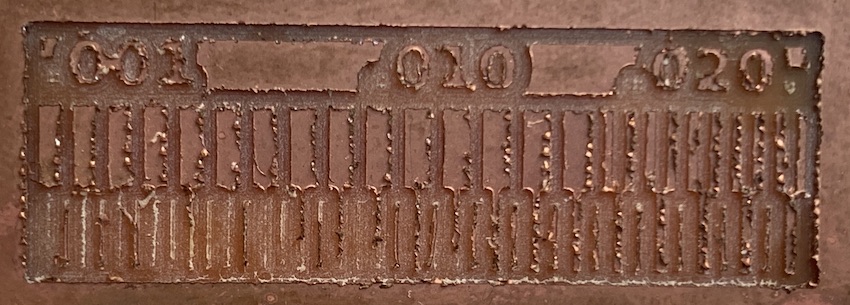
Characterization Process: Trials and Errors
–
We did so many trials and errors and it took us such a long time to characterize our PCB milling operation and finally found a good setting.
Below is the key recap summary of our trials and errors journey:
Disclaimer: We will not mention all setting details, instead, only the value that we modified / change
Test 1
Settings:
Trace:
- cut speed: 4 mm/s
- cut depth: 0.1 mm
- max. depth: 0.1 mm
- offset number: 4
- offset stepover: 0.5
Outline Cut:
- cut depth: 0.6 mm
Result:
- Very rough trace results
- It cuts the board in 2 passes only, and the cutted board fell off
Troubleshoot:
- trace speed too high
- cut depth too high, will be bad for the endmill
- we miscalculate the pcb thickness, wr thought it’s ~1.7 mm, we guessed it’s ~ 1mm
- the table where we put our machine is unstable –> might result in micro-turbulence
Test 2: reducing speed
Settings:
Trace:
- Cut Speed: 1 mm/s
- Plunge Speed: 1 mm/s
Outline Cut:
- cut depth: 0.4 mm
- max. depth: 0.99 mm
Result:
- it took longer time to cut one, around 20-ish minutes
- finer results, but still very much hairy and the lines are still very thin
Troubleshoot:
- trace speed too low
- the table where we put our machine is unstable –> might result in micro-turbulence, resulting in coarser trace
Test 3: adding speed
Settings:
Trace:
- Cut Speed: 2 mm/s
- move the CNC machine to the floor for more stable position
Outline Cut:
- max. depth: 1.27 mm [0.5 inch]
Result:
- faster cut time
- not as fine as before, eventhough lines are more visible, but still considered very thin
- uncut pcb board/ not cut all the way through
- moving the cnc to the floor doesn’t really affect significantly
Troubleshoot:
- we tried to match the resulting test with the quentorres design file to whether this line width enough to print our quentorres board. however it seems that the line will be still too thin
- still needs to add more max. depth, especially when our board is floating due to the jig
- at this point, we’re kinda stressed out with Mods, and wondering if other software will yield better results
Test 4: using Easel software
We looked up and followed the guide from Mickael Pitaressi assignment that worked similarly using our machine and our modified bed leveling mechanism. He used Easel to generate the G-Code, so we go ahead and tried that.
Settings:
Trace:
- Feed rate: 150 mm/minute
- Plunge rate: 90 mm/minute
- Depth pass: 0.1 mm
- Total depth: 0.1 mm
Result:
- showing a bit of improvement, but it seems that the software is not the problem…
Troubleshoot:
- 💡Aha! moment. It might be our endmill has been worn out, because we have no idea if the 1/64 in endmill that we used before is new or used.
Test 5: changing to new endmill
We know the endmill was the problem, so we went back to Mods. And use the Test 2 settings: Speed 1 mm/s
Result:
- Looking really good! But took forever to mill this one.. almost 45 minutes🫠
Troubleshoot:
- The speed might be too low. Now that the endmill is the problem, worth to try higher speed
Test 6: new endmill + faster speed
Settings:
Using Test 3 Setting: Cut Speed 2 mm/s
Result:
- not as clean as speed 1 mm/s
- faster cut time
- lines are still too thin
Test 7: Testing Quentorres
In the interest of time, we went straight to mill the quentorres board by using the Test 3 settings.
Result:
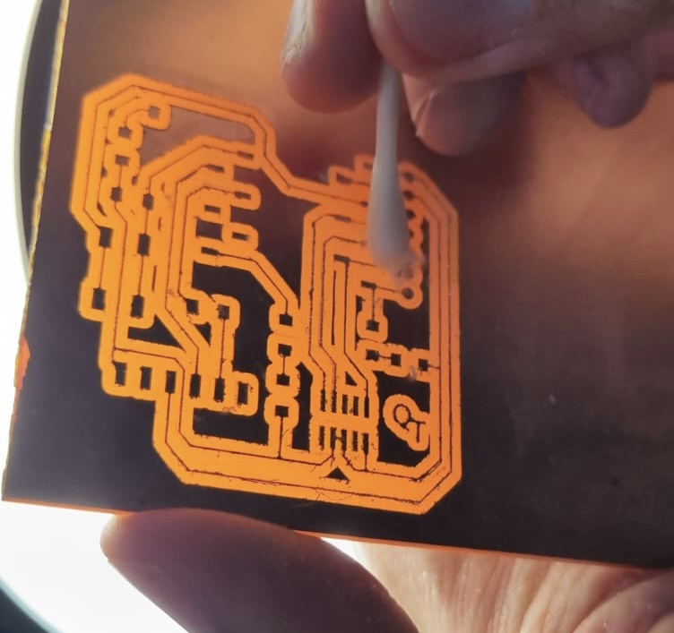
- Generally tidier, but we need to figure out how to make the line width bigger and more visible
Troubleshoot:
- reduce offset
- reduce spindle rpm
- enlarge tool diameter
Test 8 & 9: Reducing Offset, Reducing Spindle RPM, Increasing Tool Diameter
Lowering spindle speed: 8000 RPM | Offset: 2
Enlarging Tool Diameter to 4.5 mm | Offset: 2
After several more tests, we come to this settings that by far yield the best result when using 1/64 endmill:
- Offset Number: 2
- Speed: 2 mm/s
- Tool diameter: +0.5mm more --> 4.5 mm
- Spindle RPM: 10.000
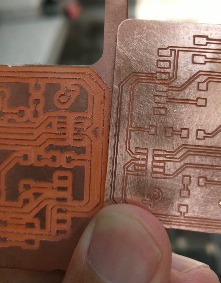
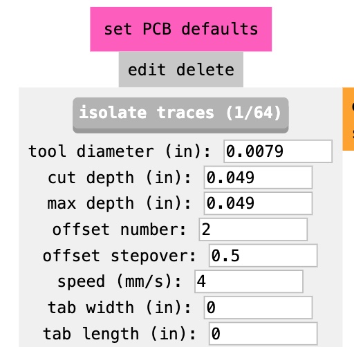
Final Result: Using V-Bit
In the end, we decided to try changing to V-bit and this is what works best for us in the end
Settings
Trace:
- Offset 2
- Speed 2 mm/s
- Tool dia 0.2 mm
- Cut depth: 0.125 mm
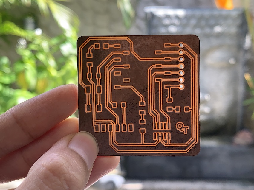
Comparison with Test 7 (quentorres milling using 1/64 endmill)