Week 05: 3D Printing
This Week’s Task
- Test the design rules for your 3D printer(s)
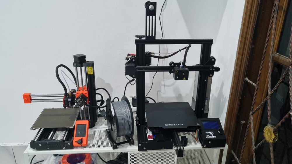
For this week’s assignment, Fab Lab Bali is mainly using PRUSA Mini+. We also have CREALITY’s Ender 3 but it had been throwing fits.... so we are using that for other purposes (will be elaborated below).
3D Printing Procedure
1. File Preparation
To conduct the design rules for our PRUSA Mini+, we collected some design files from Printables, an open-source community site for 3D printer users. There are many 3D models that you can download and to find out the design characteristics of our PRUSA Mini+, we will be utilising these:
Download the .3mf or .stl files. We will be importing these files to a slicer.
2. Slicing
A slicer is a software that does slicing; converting the 3D model file into a machine language (G-Code) that can be recognized by the 3D printer. We use PRUSASlicer for our PRUSA Mini+ printer. The UI looks like this
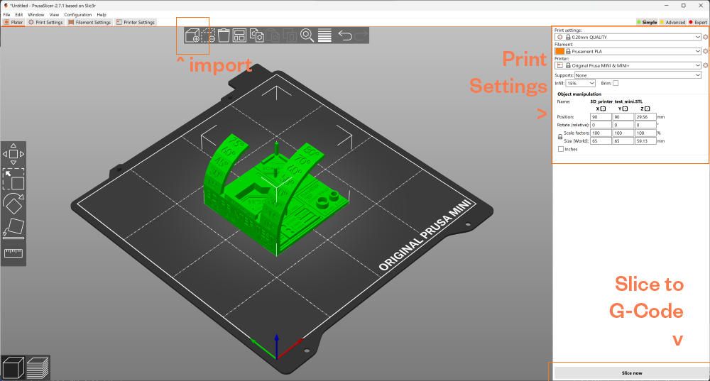
- Import your
.3mfor.stlfiles. - You can move your model around - rearrange the bed in the UI (particularly if you’re printing multiple seperate parts)
- You can tweak your print settings depending on the model.
- For example the All-In-One test model requires to be printed with 100% infill. Infill refers to the internal patterns found inside most 3D printed parts. More infill means your printed item will be denser but printing time will take longer.
- Sometimes certain print-outs will require to print with supports if there is an overhang; shapes that extend outward that are challenging to print without supports.
- Slice to get G-Code
- Once sliced, you can simulate how the print-out is going to look like layer by layer. It is recommended to go through this so you can make sure that the job is going to run smoothly and to know if your model has been designed well enough for the 3D Printer
- Once you’re satisfied, “Export to G-Code”. You can check how long is the printing time.
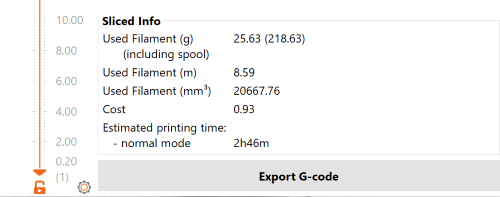
- A window will pop up and you can save it to a USB drive
3. Printer Set Up
Before printing - let us properly set up your printer
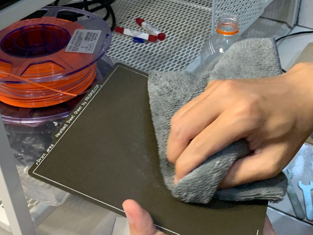
Cleaning
- Clean the bed with a cloth and IPA Alcohol to avoid any dust buildups or residues
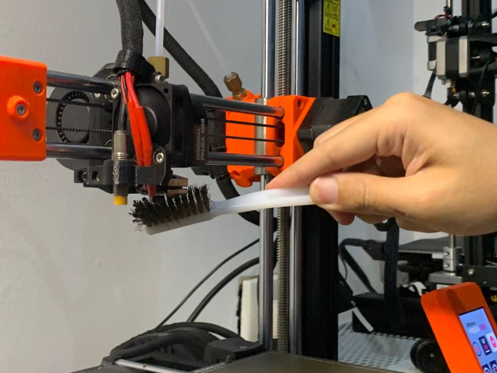
- Filament can build up overtime on your hot end. Turn up the nozzle temperature and use a brass brush to clean up the printer’s hot end.
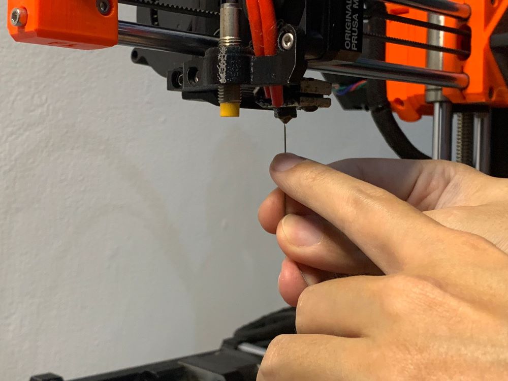
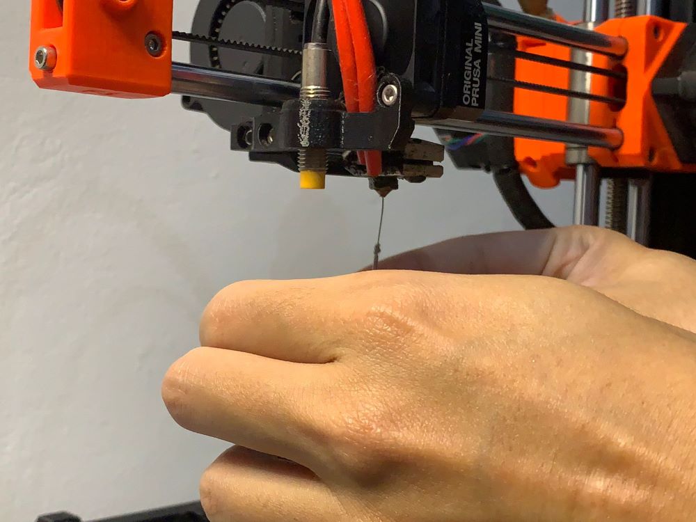
- Filament residue can also build up inside the nozzle. Turn up the nozzle temperature and use an acupuncture needle to clean up the nozzle.
Loading your Filament
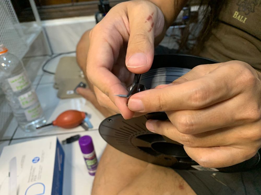
-
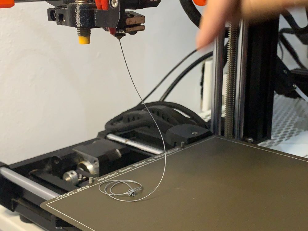
We would recommend to trim the end of your filament from the spool with a cutting pliers. Trim it 45° to make it easier for the filament to be loaded to the extruder.
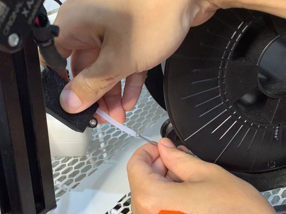
-
Insert the filament to the filament sensor until it reaches the extruder.
-
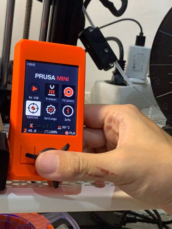
In the machine display/control -
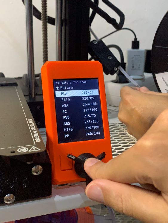
Filament>Load Filament>PLA.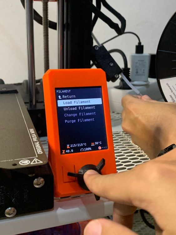
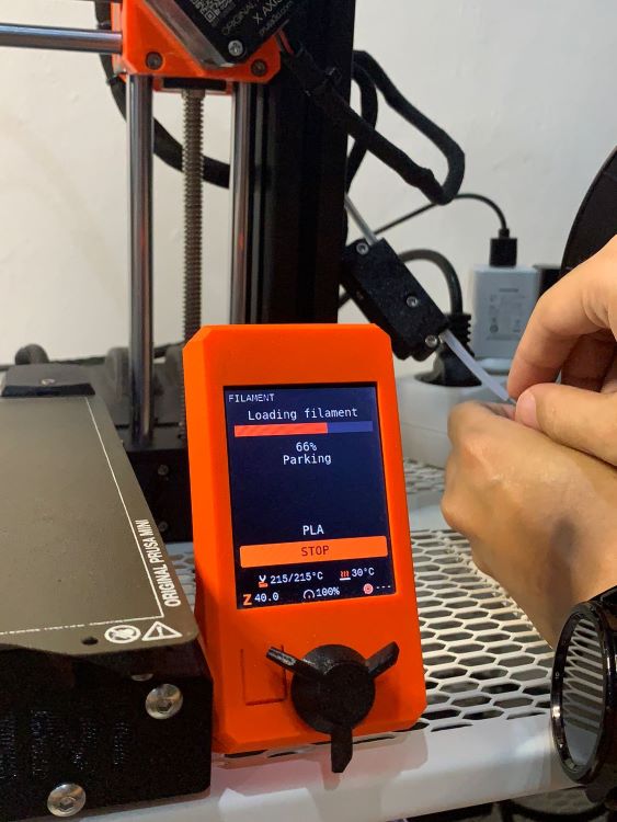
-
The extruder will hold in the filament and transport it to the nozzle. It will then purge out any remaining material from previously loaded filament.
Homing
The printer will run a homing sequence automatically before every prints. You can do it manually using Control > Auto Home command.
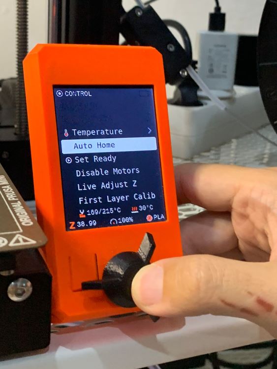
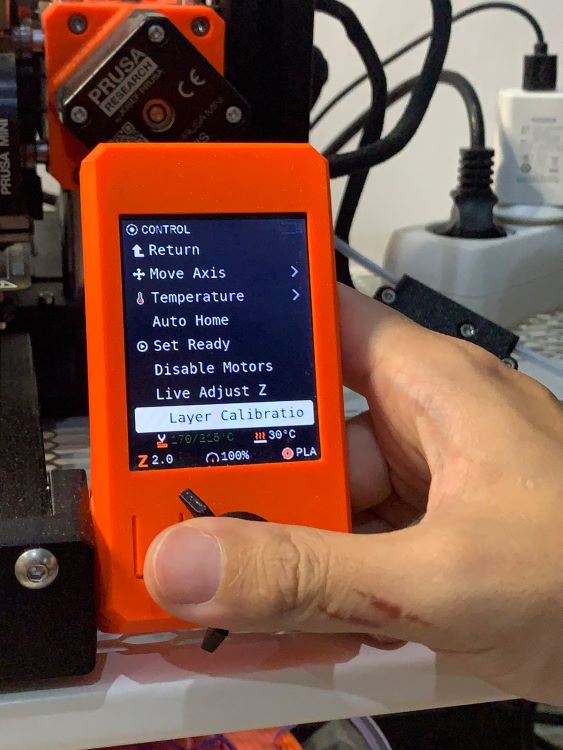
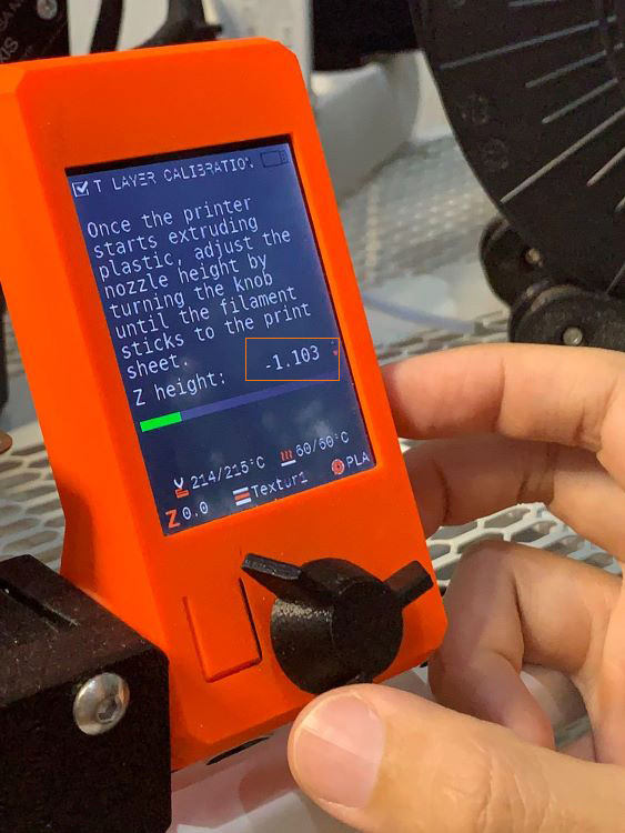
Calibration
You want to make sure that your nozzle height is also properly calibrated. To access Control > Layer Calibration.
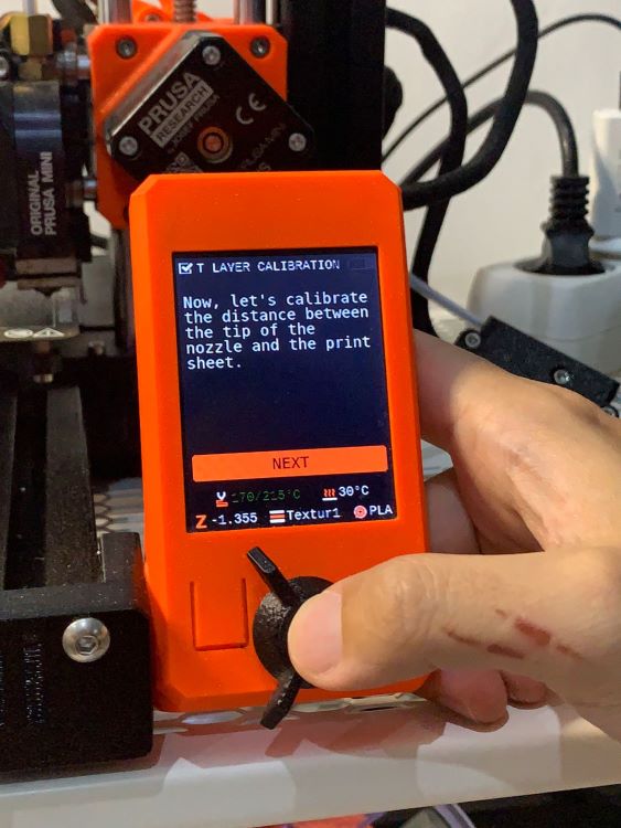
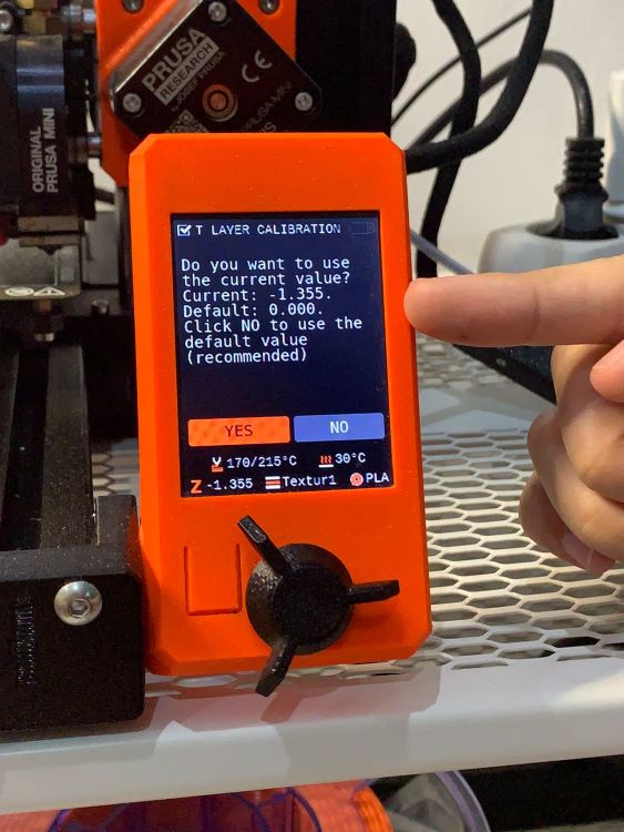
It will start extruding the filament. We found that the Default Z(0) location is a little bit too high. So we adjusted the Z to be slightly lower (-1.1) in real time.
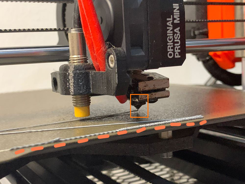
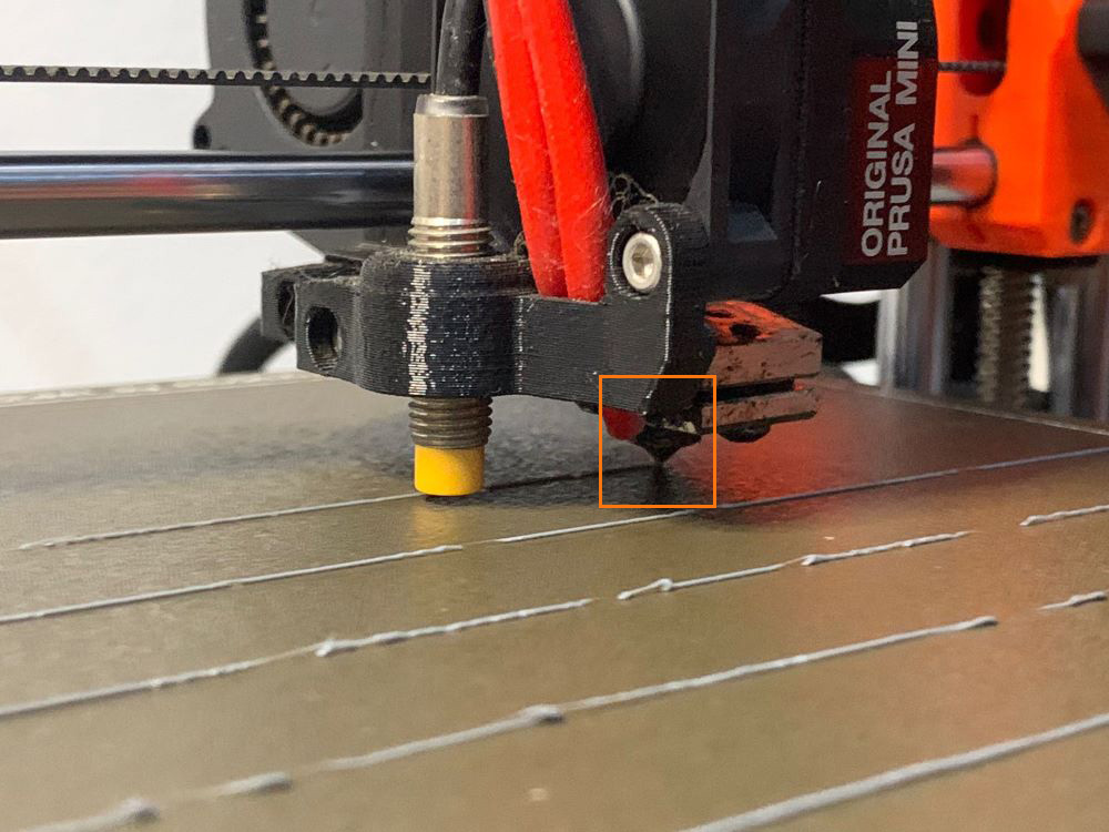
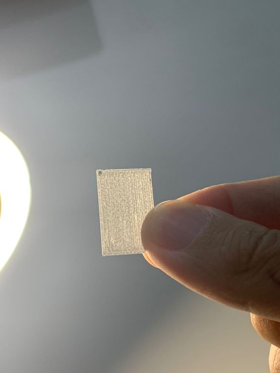
The result of layer calibration test - pretty smooth
5. Printing
Way to go! Now we can start printing, but some prior recommendations. The first layer is very critical to the success of your print out. To make sure that the first layer doesn’t peel off. Many printers nowadays has a heated bed which tremendously helps your print to stay in place, but due to our printer lacking an enclosure, heated bed alone is not enough for some challenging prints. Follow the steps below to help the first layer stick to the bed.
-
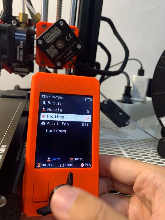
Preheat your bed by going to
Control>Temperature>Heatbed. Crank it up to 50°C then wait until it reach the temperature.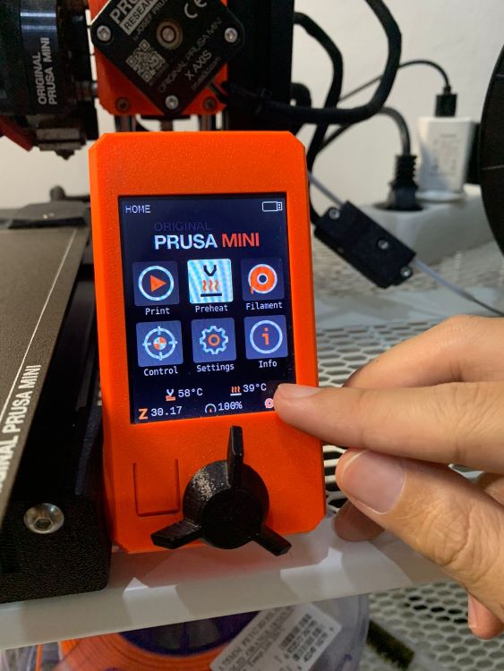
-
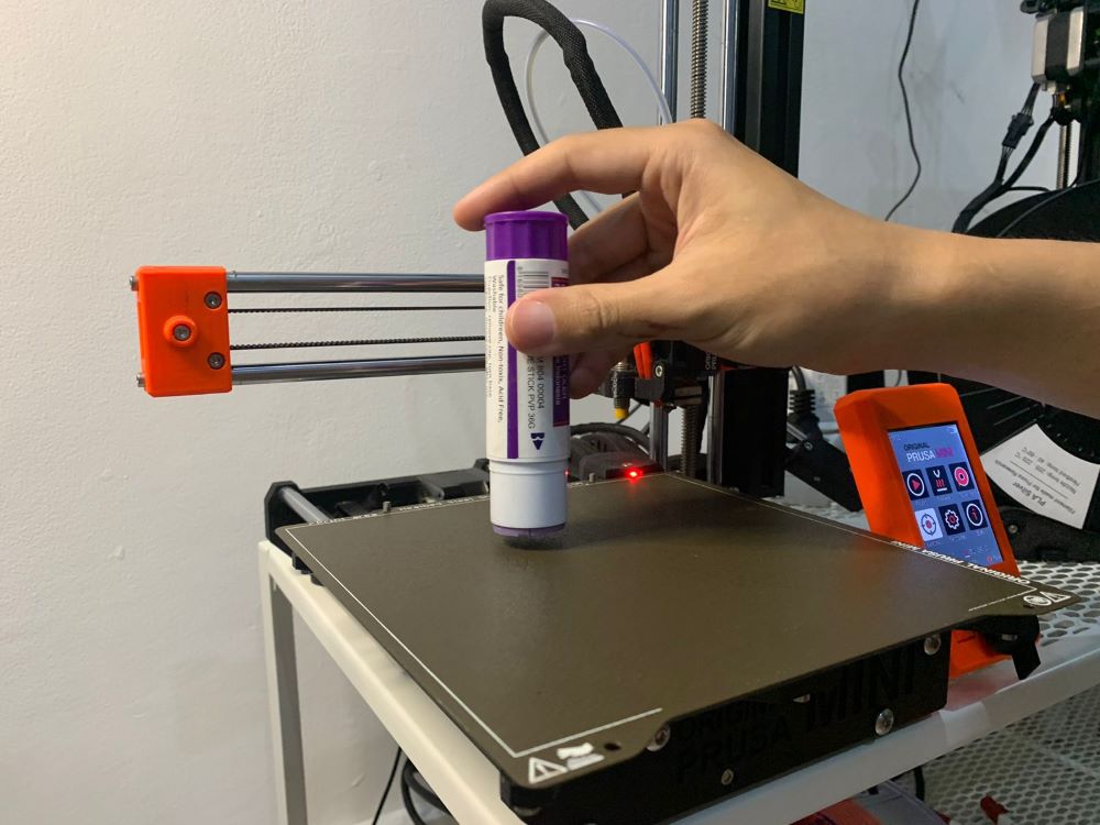
Glide a glue stick gently on the pre-heated bed to apply a thin layer of glue. Excessive glue will impact negatively to your print quality, so try to apply it as thin and even as possible.
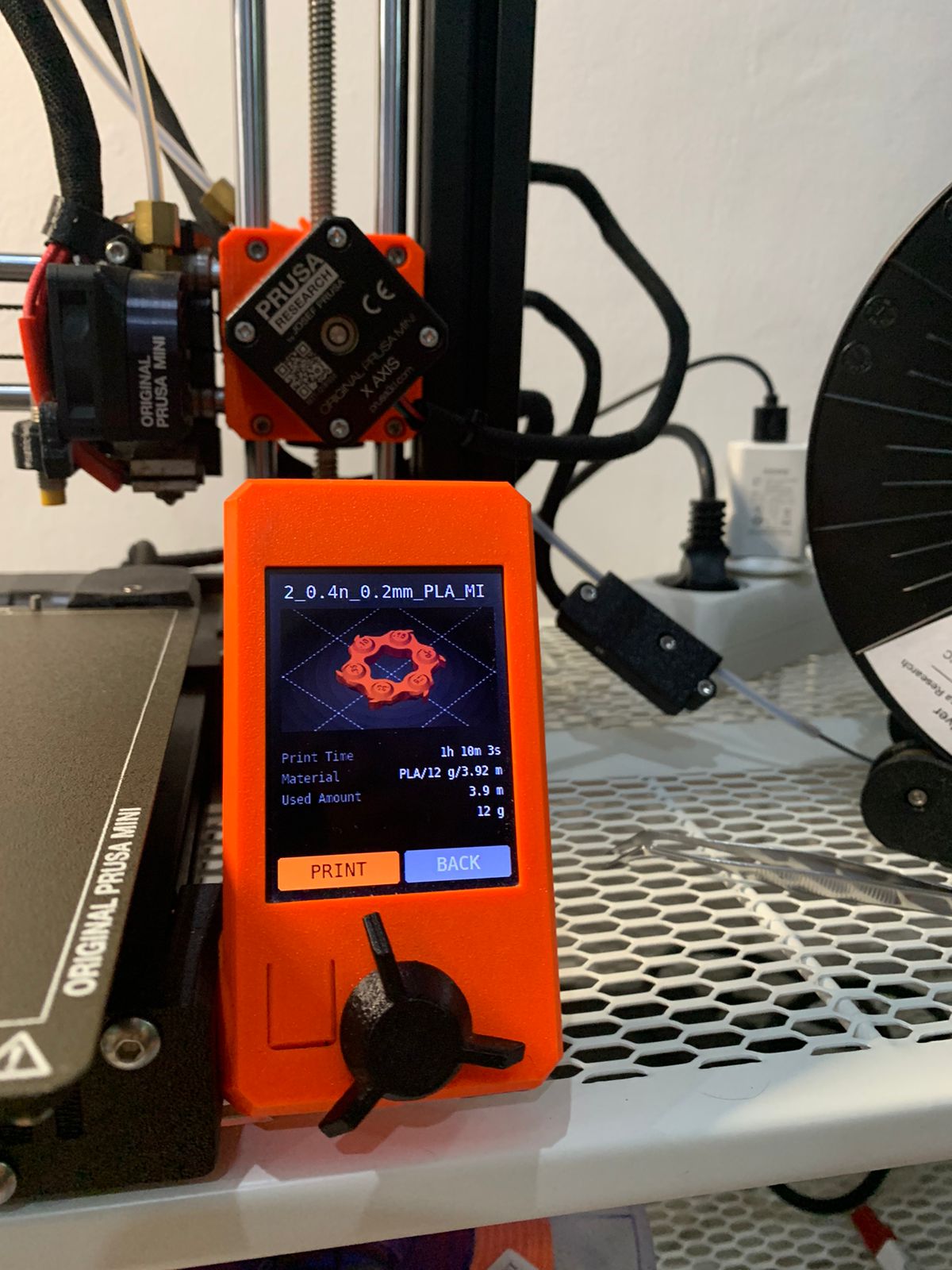
The above recommendation are some extra precaution methods to reduce the chance of your print job to mess up and turn into spagetthi noodles. Load your USB drive into the machine and the Mini+ would recognise the latest file to run. Press Print. The machine will start heating up the bed and nozzle and extrude the filament. We would recommend for everyone to watch the bed to ensure that the first layer is successfully sticking to the bed. Once that passes, you can relax and let the magic starts magic-ing.
6. Post-Processing
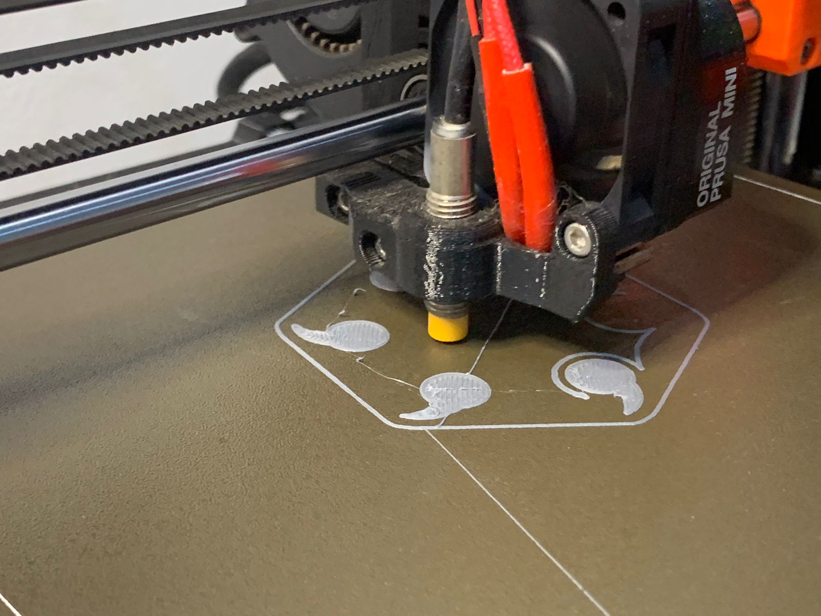
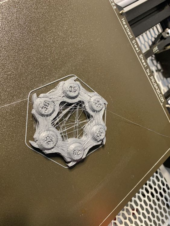
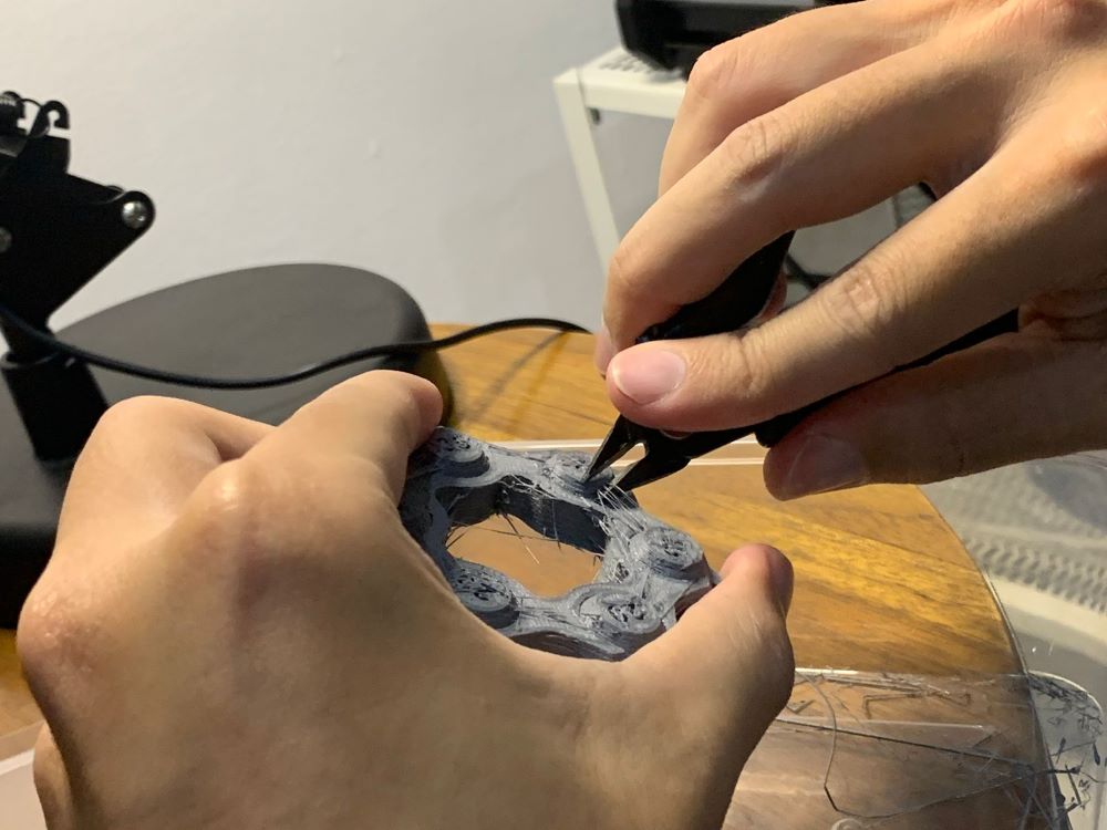
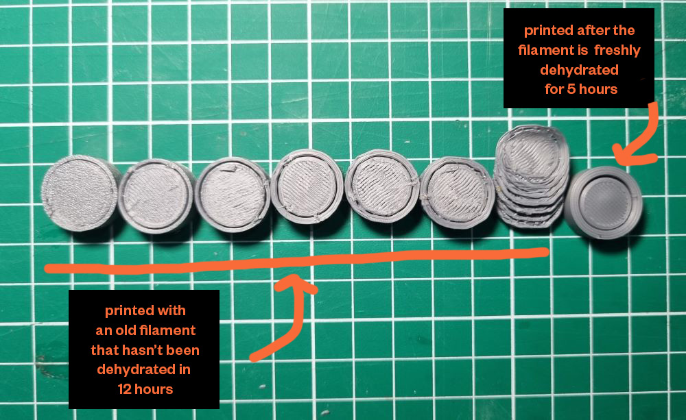
Once you have finished printing - there are chances of stringing happening especially if your filament is not in a mint condition. Clean up your model using the cutting pliers, sanding piles (if needed).
7. Maintainence
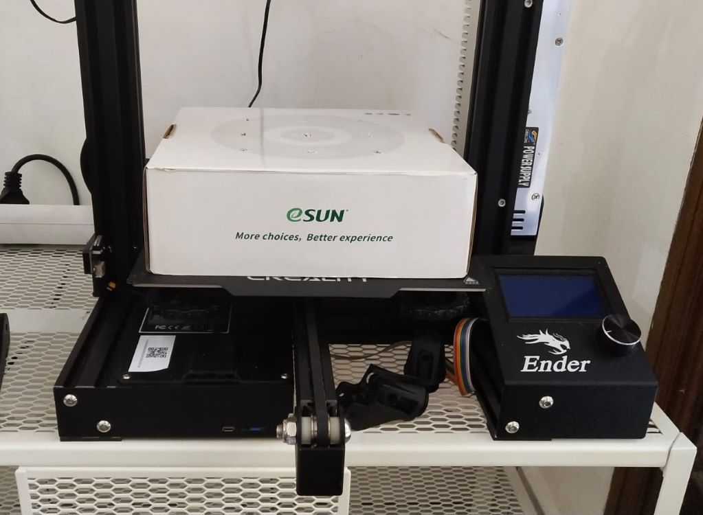
In Bali, we found that filament requires special care. Bali is pretty humid and the hygroscopic nature of thermoplastics - which can cause some extrusion dimensional flaws means that it needs to be dehydrated whenever possible. Unfortunately, we don’t have a dehydrator at the moment… so we made our Ender 3 our make-shift dehydrator. How?
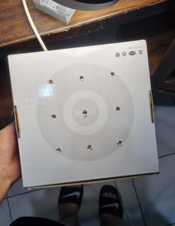
- We poked some holes to an unused filament box - this will become the cover to dehydrate the filament. The holes are poked to let evaporated air to get out.
- Turn on the Ender 3 Printer and heat up the Heating Bed to 70° C.
- Put the filament on top of the bed and cover it with the poked filament box.
- We found that for our filament - 5-8 hours of dehydration make our printed result significantly better.
Testing Design Rules
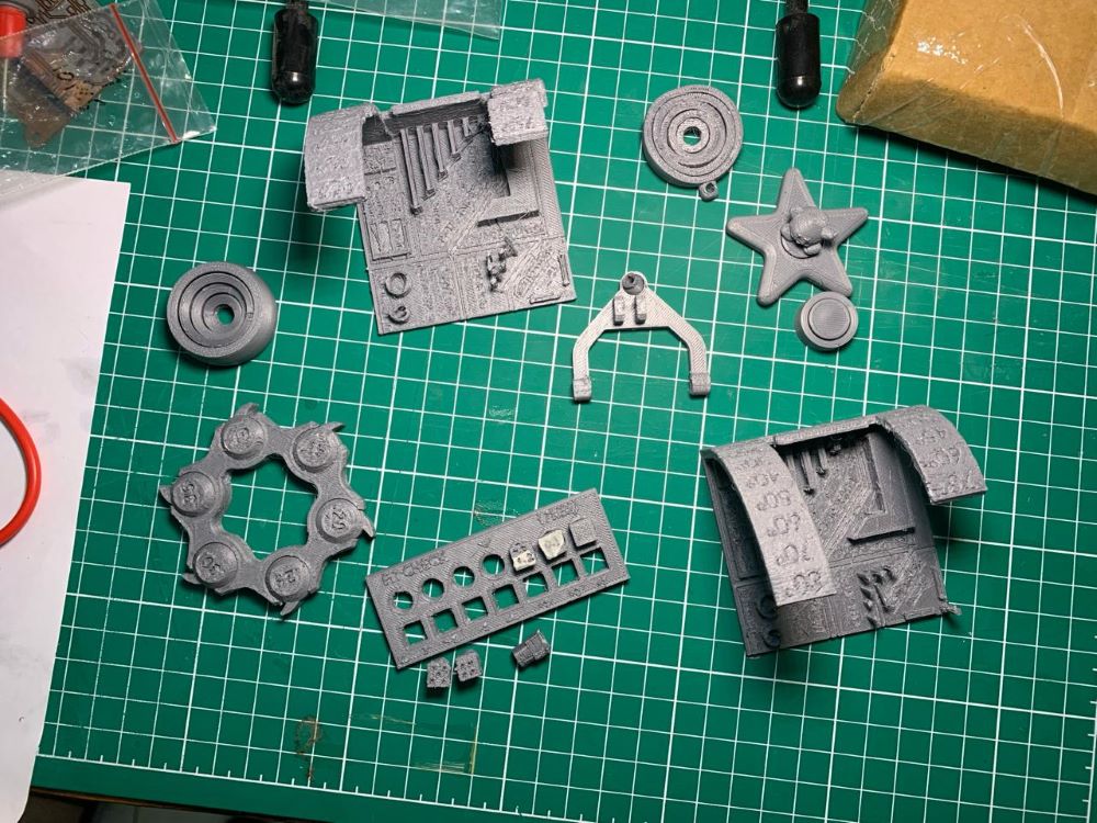
There are 3 design versions that we used for testing our design rules
All-In-One 3D Printer Test
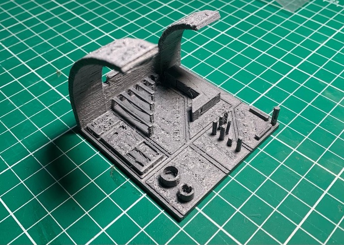
This model incorporates various kinds of test in one model, including overhang test, support test, scale test, hole test, diameter test, bridging test, and stringing test. Among these tests, we found that the most important and helpful ones to know for now is the value of Overhang, Bridging, and Diameter, especially since our ‘old PLA filament issue’ often produce a quite over-extrusion and over-stringing results.
-
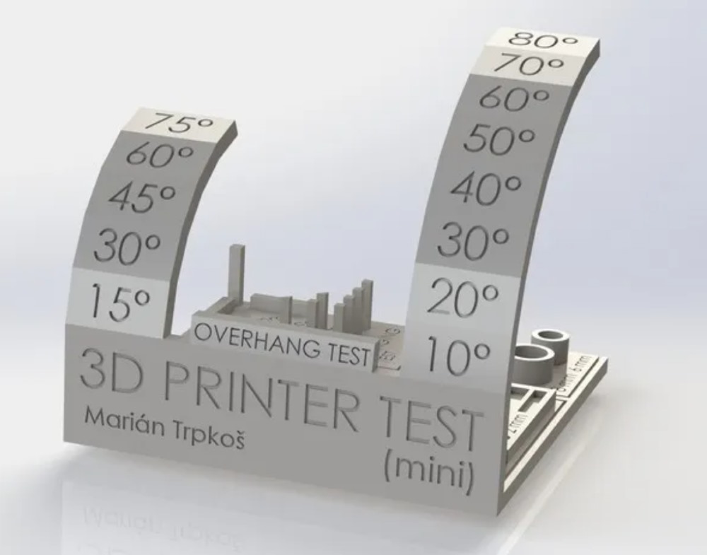
Overhang: max. 70°
The overhang test evaluates the printer’s capability to accurately produce overhanging features without the need for supports. We want to determine the maximum angle the printer can handle without sacrificing quality.
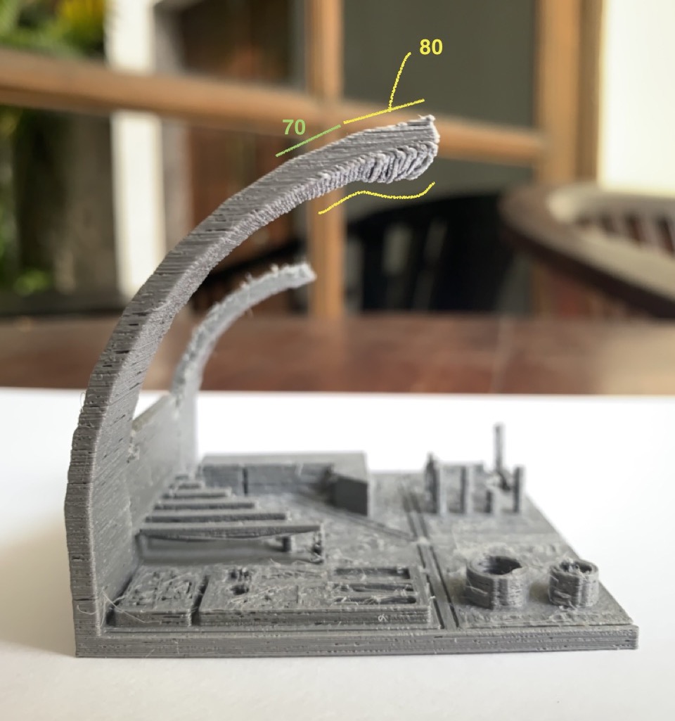
As you can see from overhang 1 (testing very 10°) result, it works still ‘quite fine’ in the 70°, eventhough some symptomps of droopiness has started to shown, but when it reach 80°, the extruded filament becomes very droopy.
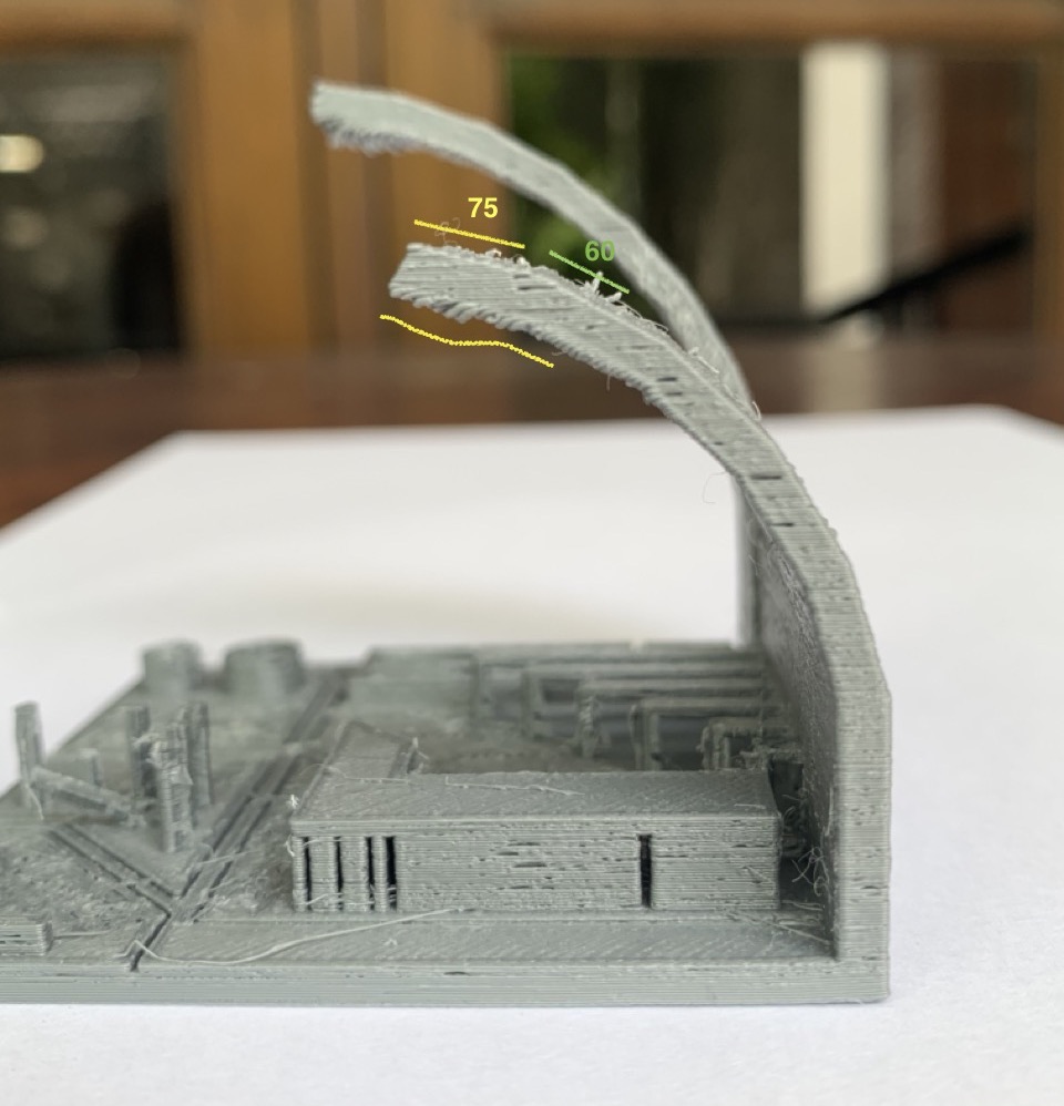
Moreover, on the every 15° test, the 75° angle also has shown some levels of droopiness. Therefore, the maximum most suitable overhang angle for achieving acceptable result is 70°.
-
Bridging: 10-15mm
Bridging test is to test the printer’s ability to create horizontal spans or bridges between two points without support structures underneath. We have to find at which maximum length the printer’s able to create stable bridges without drooping or sagging.
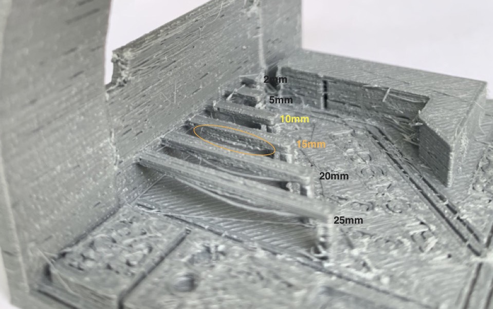
The 15mm bridging works fine overall, but you can see there’s still a little bit of sagginess there. Meanwhile the 10mm yield clean result. So, if we want to be safe and sure, it’s good to stick to around 10 mm, with a max. of before 15 mm. length bridge.
-
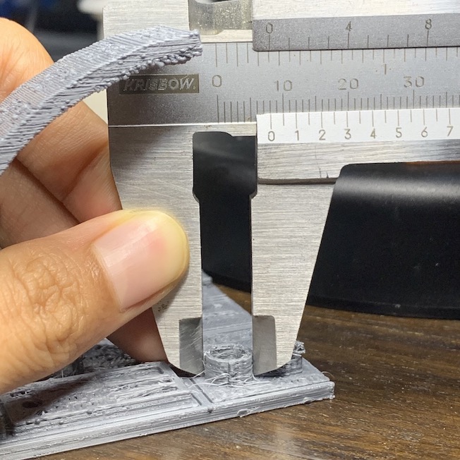
Dimension Tolerance: 0.35mm
Filament diameter consistency is crucial for achieving uniform extrusion and print quality. This test mesures the diameter of the filament using a caliper to ensure consistency.The default outer diameter size should be 8mm, wall thickness 1mm, which means the inner diameter should be 7mm.
Outer diameter: 8.05mm
Inner diameter: 6.35mm
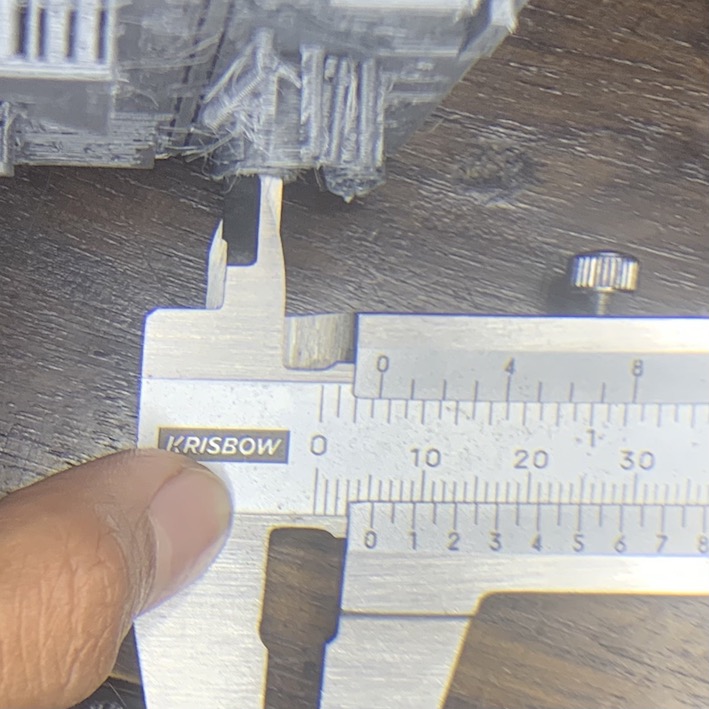
The test result shows the outer diameter is 8.05 mm and the inner diameter is 6.35 mm, which means the wall thickness ends up to be 1.7mm, given the fact that the wall thickness is 1 mm that means the width is overall shifted by 0.7mm from the intended width, which means offsetted 0.35mm to both side. Therefore, consider to account for the 0.35mm extrusion dimension tolerance value when designing.
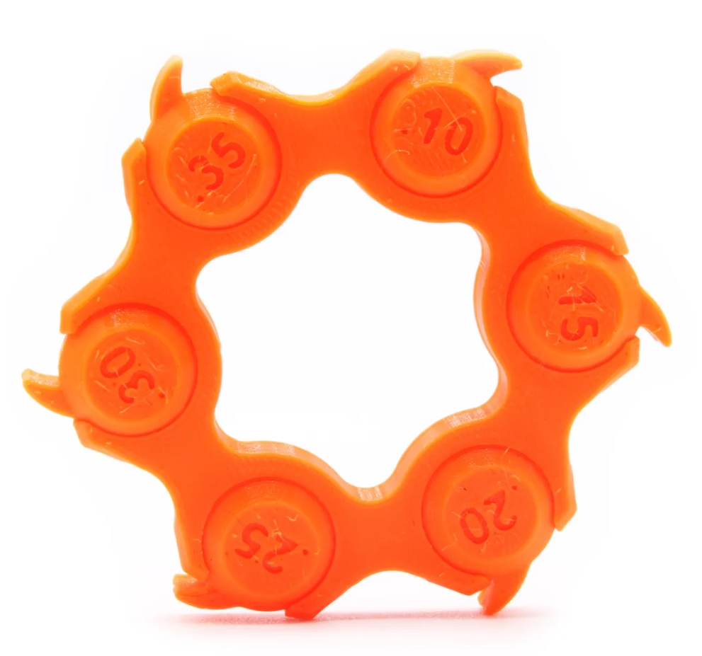
Clearance Tolerance for Print-in-Place: min. 0.15mm
The clearance tolerance is the intentional gap or space between two mating parts in a mechanical assembly. Knowing this value ensures that the parts fit together smoothly without interference or binding. This is espescially useful if we want to make a print-in-place mechanical joints.
The test model provide the range from 0.10mm gap up to 0.35mm clearance test.From the test result, it works starting from 0.15mm gap. However, just keep in mind that we achieve this result after printing the test for the 2nd time due to our old PLA filament issue. Our first test result in a clearance of min. 0.2mm. Deciding on what value to use is based on your preference. But in case you encounter similar conditions like us, it’s better to leave some room, so maybe around 0.2-0.25mm in case there are other unexpected factors, like bad filament.
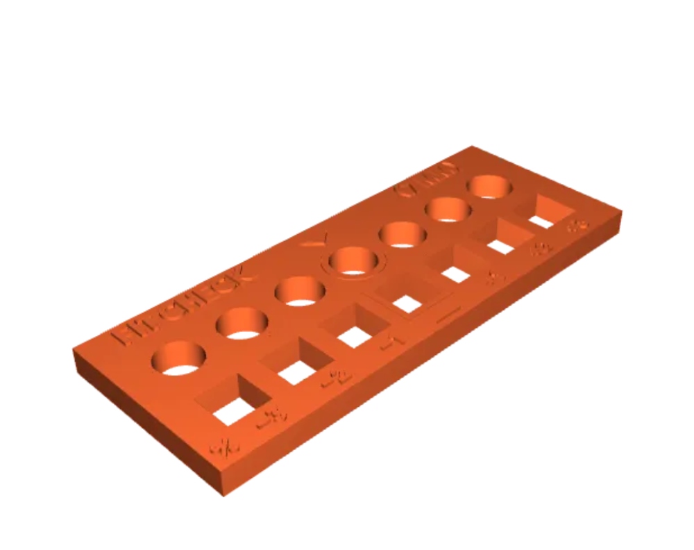
Clearance Gauge for Fit Assembly: 0.3mm
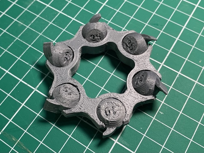
A clearance gauge test (fit check test) is used to verify the clearance between two parts in a 3D-printed assembly. This test let us know if we want to 3d print parts for assembly, what holes width or button width dimension is ideal.
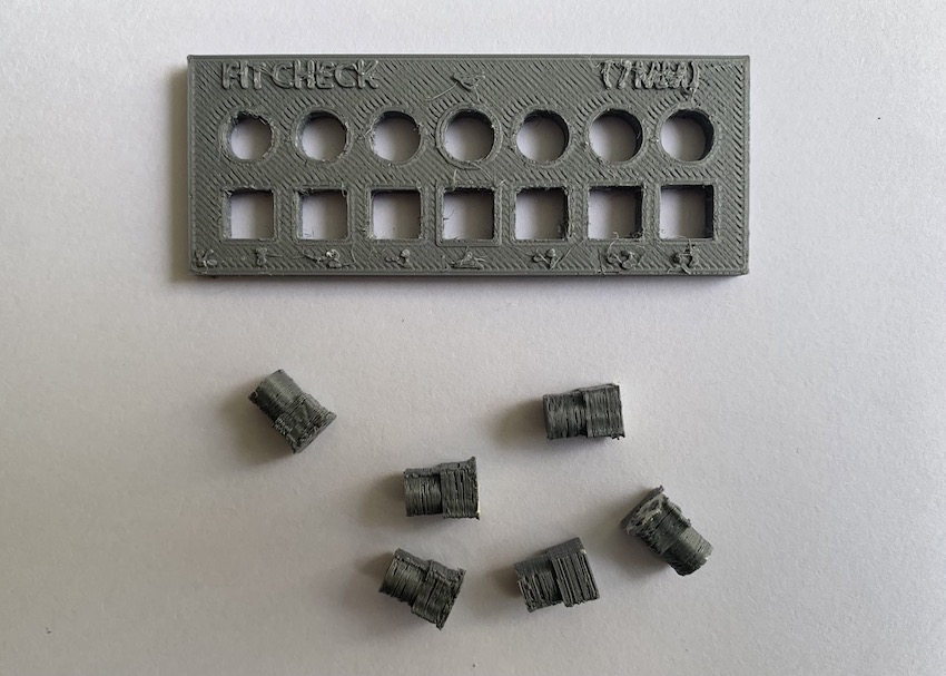
In this model, we can test two types of holes: round and square. The default diameter of the circle hole and the width of the square hole is 7mm, which increases every 0.1mm until +7.3mm and decreases every 0.1mm until -6.7mm The same goes for the buttons, only that it decreases every 0.1mm until -0.5mm. Ideally, the default hole will be match with the button.
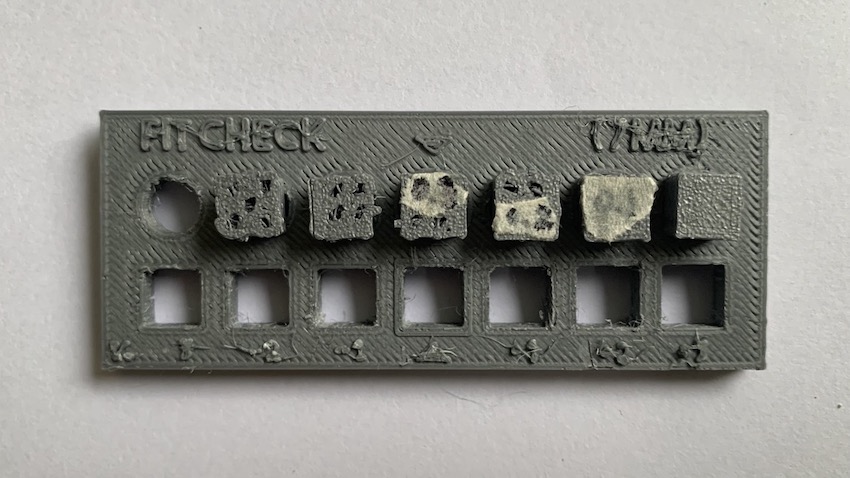
However, based on the result, we can see that the default 7 mm button is match with the 7.3mm holes, which means there are a shift of +0.3mm in the printed results. Therefore the fit clearance is 0.3mm. This result is in synced with our previous dimension tolerance test, which validate that the tolerance/clearance is 0.35mm.
The implication of this is when designing is for example, if the button dimension is fixed, then you have to add 0.3mm clearance in the holes. Or, if the hole dimension is fixed, then you have to reduce the dimension by 0.3m.