Computer Controlled Cutting
This week’s experiment involved leveraging Geometry Nodes in Blender to generate G-code files directly for applications in laser cutting. This method uses attribute and field-based aproach to create parametric toolpaths for various CNC machines, including laser cutters and drawing machines. The technique allows for the direct manipulation of speed and power settings in the G-code, facilitating nuanced material cutting and engraving processes.
- Blender + Geometry Nodes: Used for designing and generating toolpaths.
- Python: Scripting for G-code exporting.
- CNCjs: Software for executing G-code on machines.
- Sculpfun S9 Laser Engraver: The hardware used for actual material cutting.
I adapted the file showcased by Rico Kanthatham (tutorial here), making several modifications to fit the specific requirements of my project:
Step 1: Modifying Geometry Nodes file
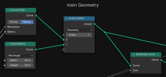
- Shape Toggle: Introduced an index switch node to toggle between quadrilateral and circular shapes.
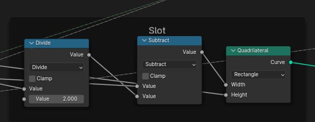
- Kerf Adjustment: Added a division step before subtraction to compensate for laser kerf, ensuring precise fits.
- Path Closure: Included a start point at the end of each path to properly close each cut.
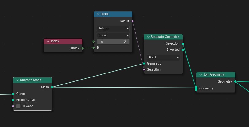
- Cut Order Visualization: Utilized a cylinder to preview the sequence of cuts.
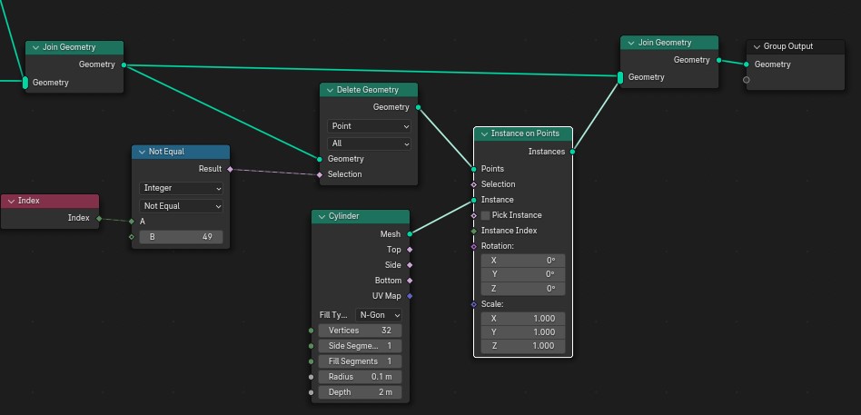
- Speed and Power Attributes: Embedded these attributes directly in the design for dynamic testing.

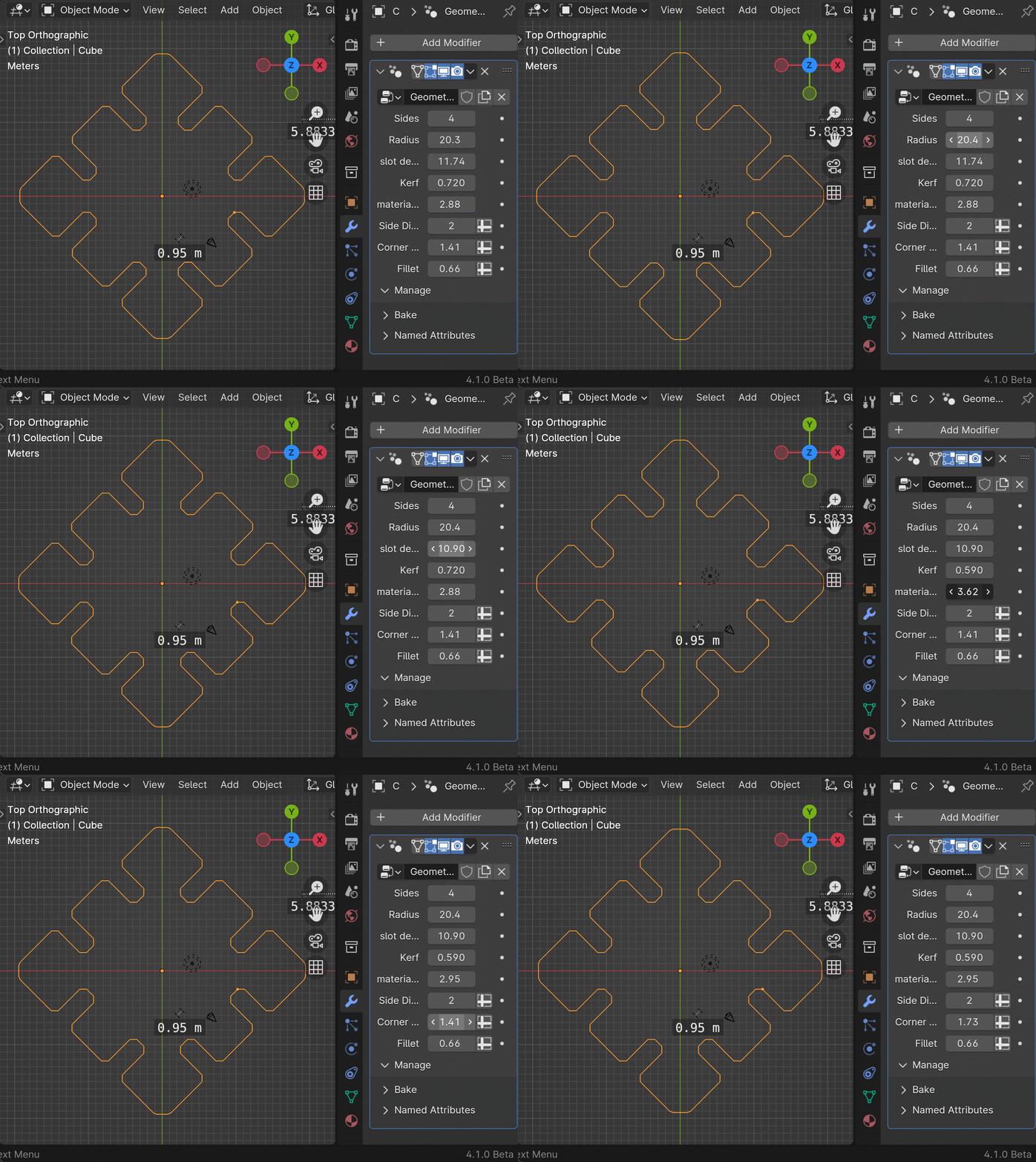
Blender offers a full python interpreter inside itself, to use it there is a terminal and also you can use the text editor to run a script.
in this case the Sculpfun S9 Laser Engraver takes standard Gcode
A common Gcode for a laser looks as follows:
G1 X100 Y100 Z 100 F100 S100
in this case the XYZ values provide the next movement, G1 means linear movement, F sets the speed the laser is going to move and S sets the “power” of the laser.
In order to be able to “extract” the position, power and speed attributes for each point, I wrote a Python script transforms this attributes into G-code commands, specifying laser power and movement speed.
For using it copy and paste this code on the python script editor inside blender, select your toolpath and click on the play
button on top of the python scripting editor window.
this will generate the ouput.gcode file that you need to save and load on your laser cutter.
Initial engraving attempts revealed areas for improvement:
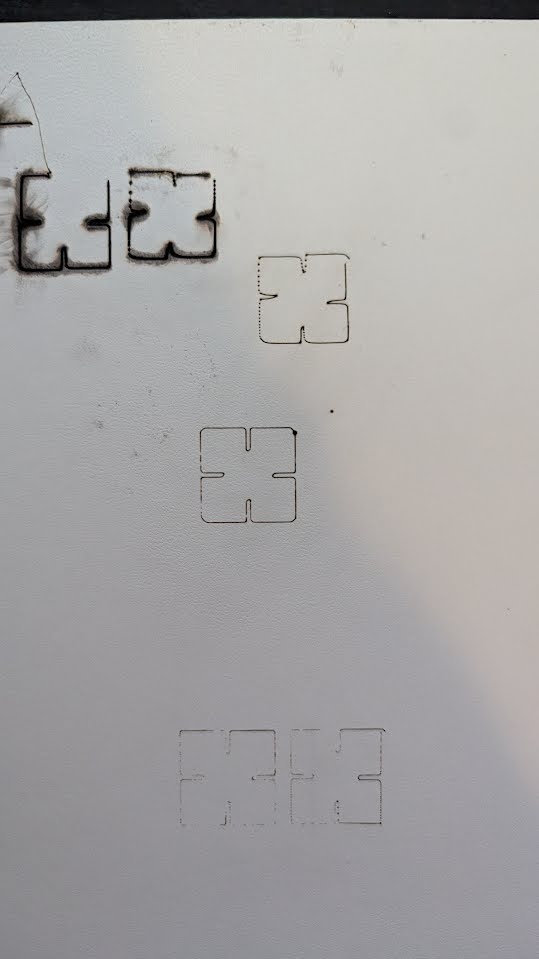
Important Safety Notice:
- Start and end files in Blender should contain simple commands to activate and deactivate the laser (M3 to start, M5 S00 to stop).
- Set the power attribute of each path’s starting point to 0 to avoid unwanted connecting lines.
- Exercise caution: This method is experimental. Use at your own risk, and be aware of the potential for damage or injury.
1
2
3
4
5
6
7
8
9
10
11
12
13
14
15
16
17
18
19
20
21
22
23
24
25
26
27
28
29
30
31
32
33
34
35
36
37
38
39
40
41
42
43
44
45
46
47
48
49
50
51
52
53
54
55
56
57
58
59
60
61
62
63
64
65
66
67
68
| import bpy # Imports Blender Python API for access to Blender's data structures and functions.
def append_to_text_block(target_text_name, text):
# Checks if the specified text block exists within the Blender project.
if target_text_name in bpy.data.texts:
target_text = bpy.data.texts[target_text_name] # Retrieves the specified text block.
target_text.write(text + "\n") # Appends the provided text with a newline to the text block.
else:
print(f"Text block '{target_text_name}' not found.") # Prints an error if the text block does not exist.
def get_text_content(text_name):
# Retrieves the content of a specified text block if it exists.
if text_name in bpy.data.texts:
return bpy.data.texts[text_name].as_string() # Returns the content of the text block as a string.
else:
print(f"Text block '{text_name}' not found.") # Prints an error if the text block does not exist.
return None # Returns None if the text block does not exist.
def format_gcode(x, y, z, speed=None, power=None, laser=True):
# Formats the parameters into a G-code string.
gcode = f"G1 X{x:.4f} Y{y:.4f}" # Basic G-code command for moving to a specified X, Y position.
if not laser:
gcode += f" Z{z:.4f}" # Adds the Z position if not using a laser (for CNC machines).
if speed is not None:
gcode += f" F{speed:.2f}" # Adds the feed rate (speed) if specified.
if power is not None and laser:
gcode += f" S{power:.2f}" # Adds the laser power if specified and in laser mode.
return gcode # Returns the formatted G-code string.
# Name of the text data-blocks used for storing the G-code and setup/teardown procedures.
main_text_name = "output.gcode"
start_text_name = "start"
end_text_name = "end"
scale = 1 # Scale factor for vertex positions.
# Ensure the main text block exists or creates it if it doesn't.
if main_text_name not in bpy.data.texts:
bpy.data.texts.new(main_text_name)
# Append the start text content, typically used for machine setup commands.
start_content = get_text_content(start_text_name)
if start_content is not None:
append_to_text_block(main_text_name, start_content)
# Get the active object and prepare to append vertex data as G-code.
obj = bpy.context.object.evaluated_get(bpy.context.evaluated_depsgraph_get()).data
if 'position' in obj.attributes:
# Retrieves position, speed, and power data from the object's attributes.
positions = obj.attributes['position'].data
speeds = obj.attributes['speed'].data if 'speed' in obj.attributes else [None] * len(positions)
powers = obj.attributes['power'].data if 'power' in obj.attributes else [None] * len(positions)
# Iterates through each vertex to generate and append G-code based on position and optionally speed and power.
for pos, speed, power in zip(positions, speeds, powers):
x, y, z = pos.vector * scale # Applies scale factor to vertex position.
speed_val = speed.value if speed else None # Retrieves speed value if it exists.
power_val = power.value if power else None # Retrieves power value if it exists.
message = format_gcode(x, y, z, speed_val, power_val) # Formats the G-code for the vertex.
append_to_text_block(main_text_name, message) # Appends the G-code to the main text block.
else:
append_to_text_block(main_text_name, "Position attribute not found.") # Error message if position attribute is missing.
# Append the end text content, typically used for machine shutdown commands.
end_content = get_text_content(end_text_name)
if end_content is not None:
append_to_text_block(main_text_name, end_content)
|
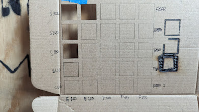
The first file is the characterization test, in this file i make an array of squares, each one with incremental speed on one axis and incremental power on the other. This allows me to find out what are the correct settings for that specific material quickly.
A speed of 200 and power of 300 looks like a balanced choice to avoid burning and cutting throw on one go:
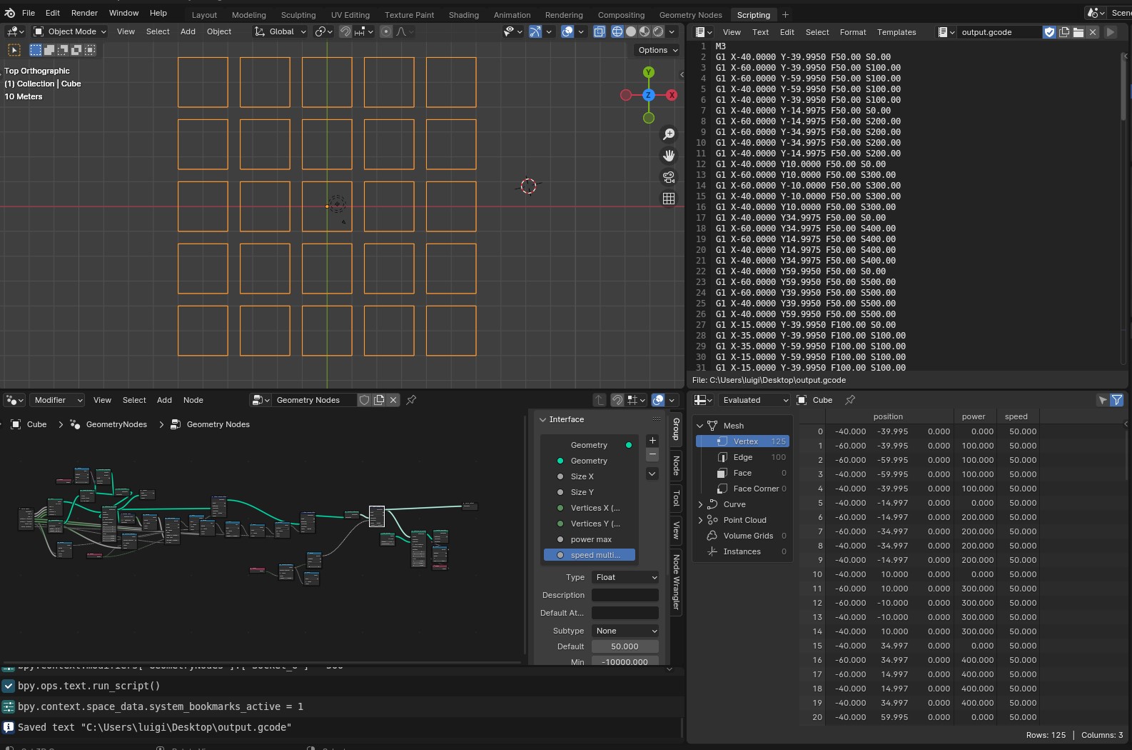
Here is the full Geometry nodes setup

Now I opened the gcode on CNCJS, connected to the laser cutter with the USB serial and clicked on play
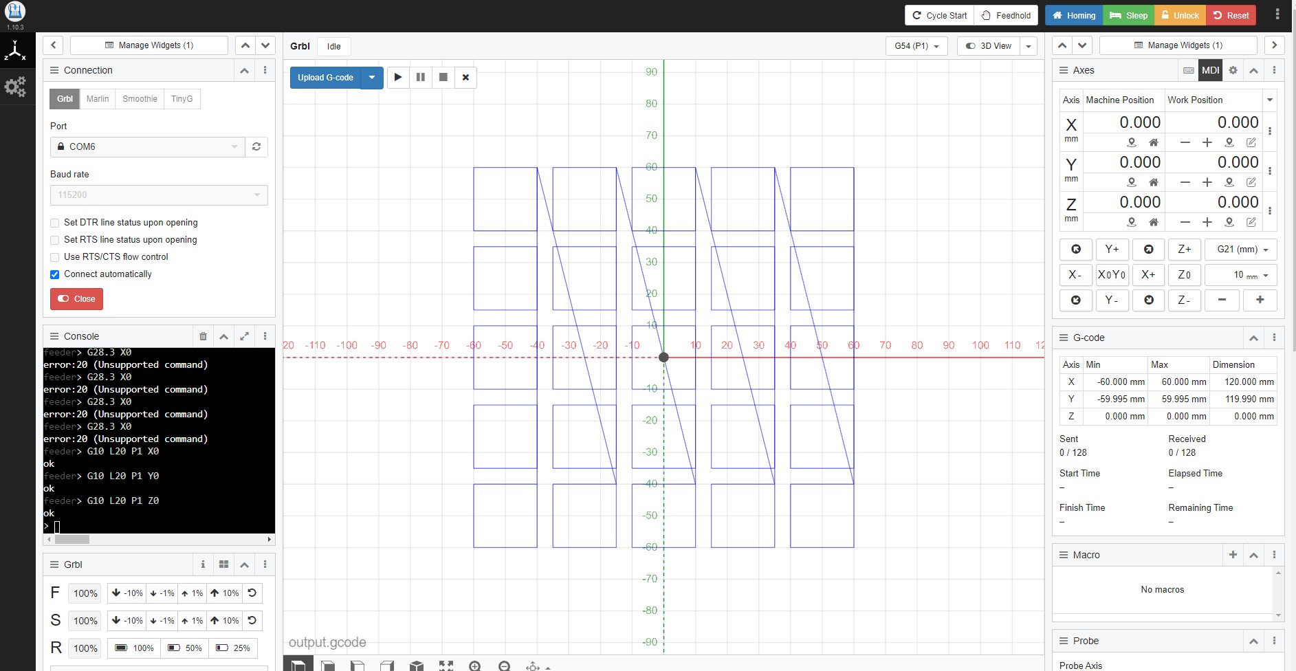
this is the final result:
Using the parameters parameters power 400 speed 200 , I successfully cut out my press fit kit file:.
Vinyl cutting
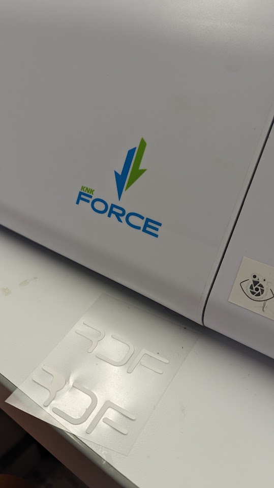
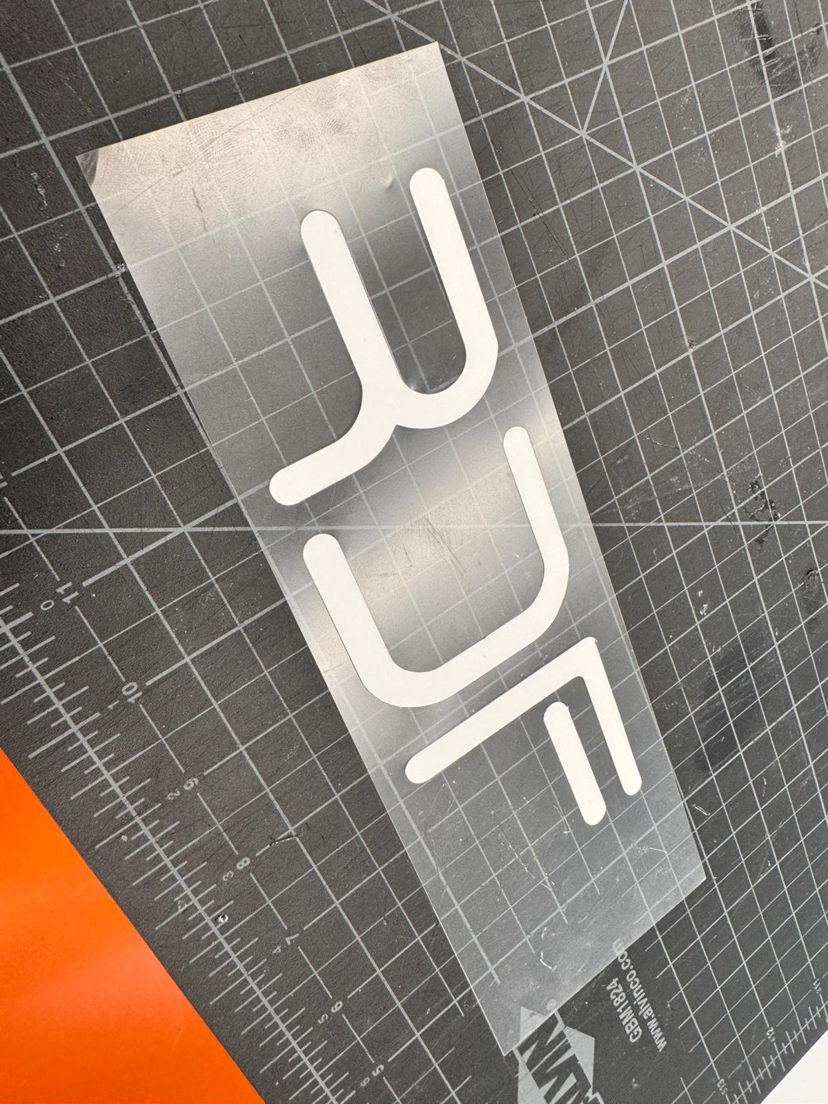
Additionally, I exported the Labs logo for vinyl cutting:
this logo was generated in Inkcape and printed it to the plotter, this process was straigh forward as all you do is send the SVG to the plotter as with any printer and it generates custom gcode to cut the paths.
here are the steps to use the KNK cutter:
Setup:
Materials:
- KNK Force
- Charging Cable (has a sticker on it that says “KNK”)
- WIFI Adapter or Ethernet cable
- Cutter blade
- Cutting Mat
- Pen (necessary for print and cut only)
For Ethernet Connection:
Plug the ethernet and charging cable only.
Connection:
- Press the start button.
- A blue light will blink (might take up to 1-2 minutes).
- Another light will appear after the blinking:
- If it is Red: KNK doesn’t receive a connectable WIFI signal (WIFI adapter is required).
- If it is Green: KNK is in recovery mode and needs a manual reset. See the instructions below.
- If it is White: KNK is ready for the next step.
- Open WIFI settings from your PC and choose KNK_Force network.
- KNK is now connected to the PC.
Problems with the connection?
Check Article 2.02.2 in the PDF.
Software:
- Inkscape is compatible with the device.
- IP address includes a software to cut svg files from inkscape.
First Cut:
- You’ll need an IP Address to start cutting.
Cutting:
- After you get the IP, type it into your browser address.
- An Interface for KNK will show up.
- Prepare a design from Inkscape for cutting.
- After designing in Inkscape, follow File>Save As…>[Name of your file] and select .svg.
- Open up the browser again and select “Upload a new SVG pattern:”
- Select your design and wait for the upload. Then return to the main page.
- Set up your tool (see instructions below)
- Place your mat and material (Check Article 1.10 for the mat details)
- Select “Prepare this cutting job”
- Adjust the starting position of your KNK using arrows and numpad (Depends on the mat and material size)
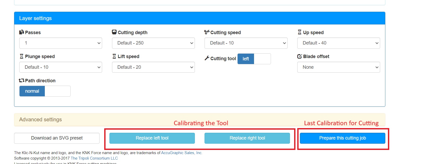
- Setup for the tool is needed after EVERY TIME you turn KNK on.
- In the browser UI, select the replace left tool (ALWAYS use the left slot for single tool)
- Take every tool out if they were left there in the previous session and click continue
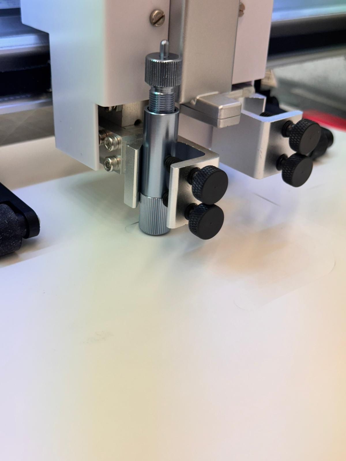
- Put the tool back in and adjust the screws.
- The tool is set up! For pen or blade tension and adjustments, make sure you read Article 1.08 in the PDF.
After sending to cut you can use Get out the Vynil stickers. and use them anywhere you need :).
Files