Week 05. 3D Scanning and printing
Let us measure and create...
Group Assignment (link)
Test the design rules for your 3D printer(s)
Individual Assignment
Design and 3D print an object (small, few cm3, limited by printer time) that could not be made subtractively
3D scan an object (and optionally print it)
3D Scanning
Data Capture
Drone
Detail drone capture
iPhone
Detail phone capture
Pix 4d Capture - link
Photo Scan – linkData sets – folders of images
Reality Composer Pro
Easy Photogrammetry on Apple Silicone Mac
Pre-requisite for this – have captured data set using some capture app or digital camera – images with at least 80% overlap and ideally in order. Pre-check the images and delete any blurry or images that might not be suitable.
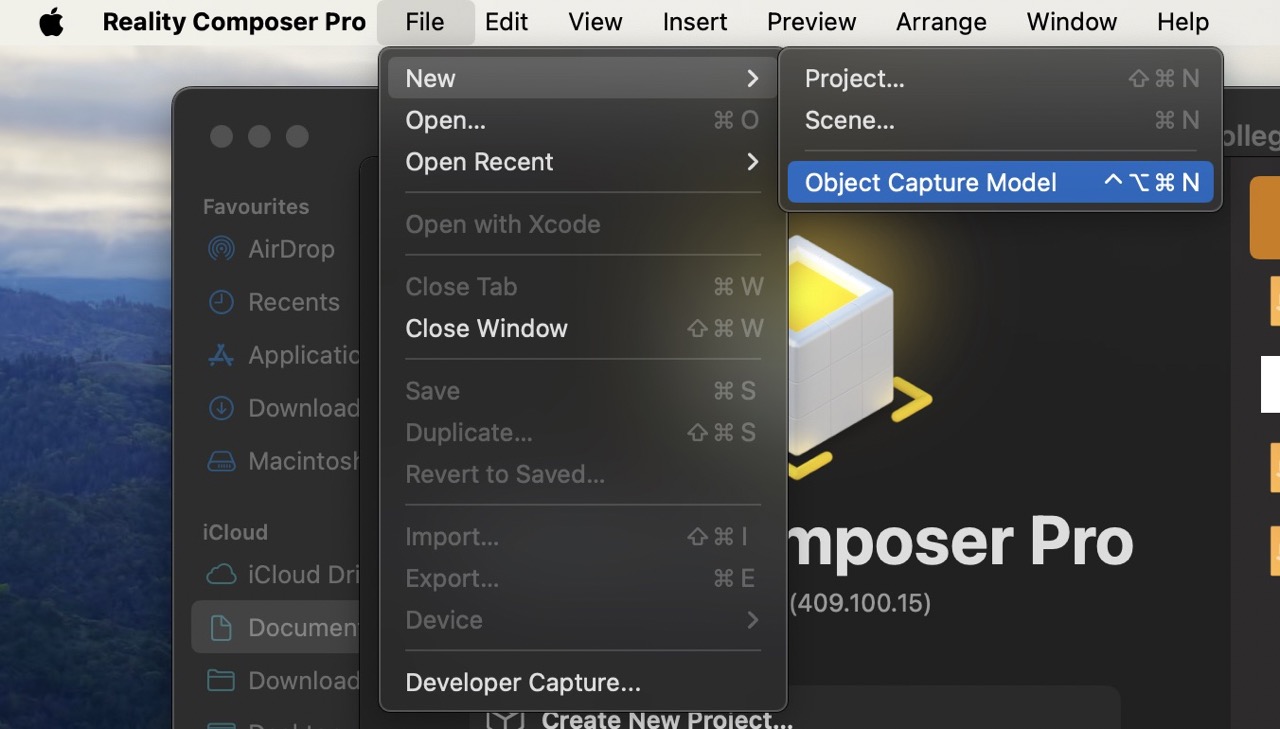
You are using two different data sources to move all images (and any other files or data with the images) into one folder. Note this will only work on Apple silicone laptops (I had to borrow my wife's laptop one night to run this… shhhh don't tell her) Download and install X Code from the Apple app store.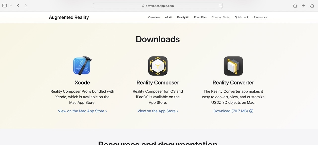 when installed search for Reality Composer Pro and open.
Once opened go File>New>Object Capture Model
when installed search for Reality Composer Pro and open.
Once opened go File>New>Object Capture Model
 We can now add (drag and drop) the folder with all images into the canvas area. I had to move the drone images from their original folder into this new folder, don't just move the folder, move all the files from that folder into the other folder – you can't have folders in folders.
Any additional data in the folder I moved also – this could contain useful metadata or lidar data and other info that Reality Composer Pro could potentially use to assist with reconstruction. Note the size of this folder is over 2GB and has over 300 images between the two data sets. I realise this may be overkill however I believe more is better when it comes to photogrammetry – we need approx. 80% overlap in images.
We can now add (drag and drop) the folder with all images into the canvas area. I had to move the drone images from their original folder into this new folder, don't just move the folder, move all the files from that folder into the other folder – you can't have folders in folders.
Any additional data in the folder I moved also – this could contain useful metadata or lidar data and other info that Reality Composer Pro could potentially use to assist with reconstruction. Note the size of this folder is over 2GB and has over 300 images between the two data sets. I realise this may be overkill however I believe more is better when it comes to photogrammetry – we need approx. 80% overlap in images.
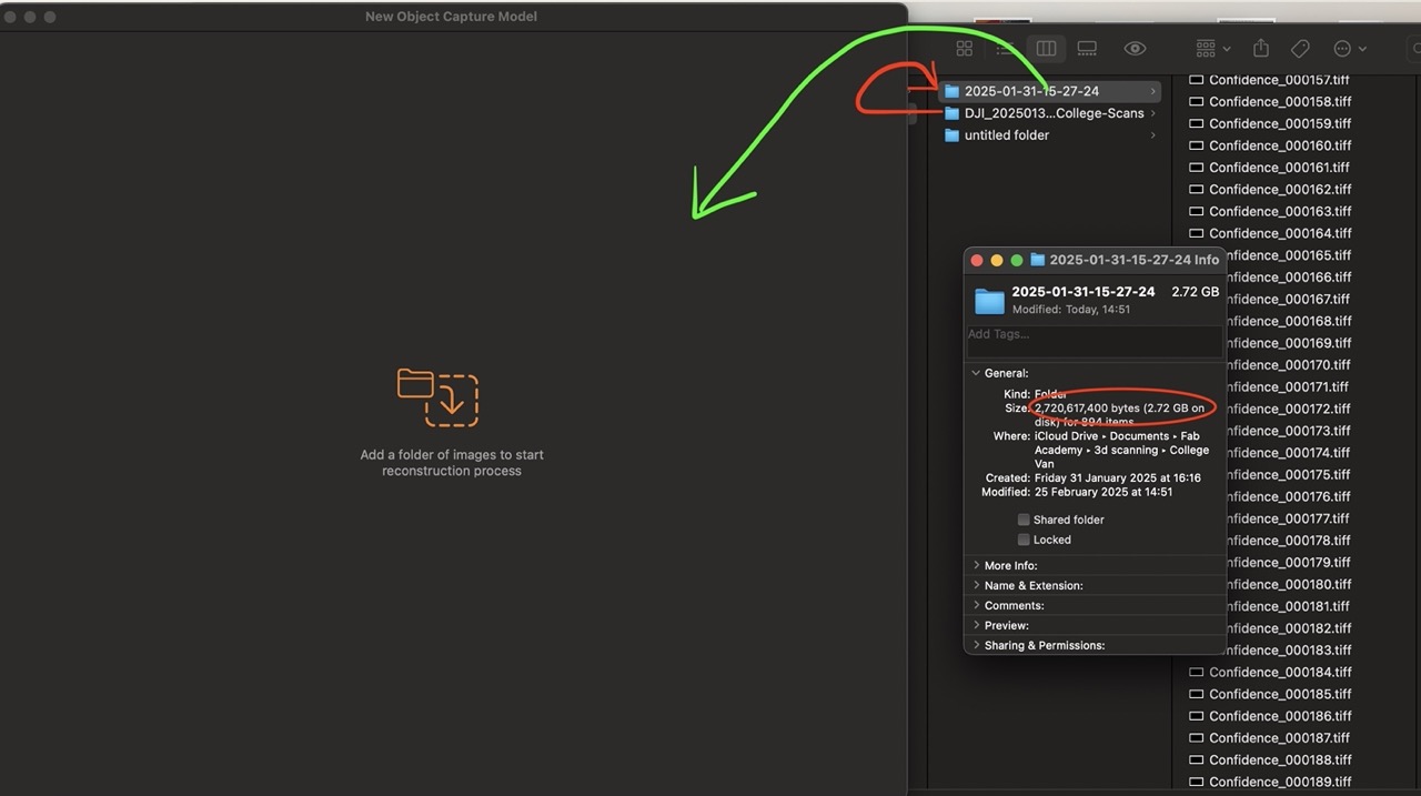 once imported you should see a preview of images in the canvas.
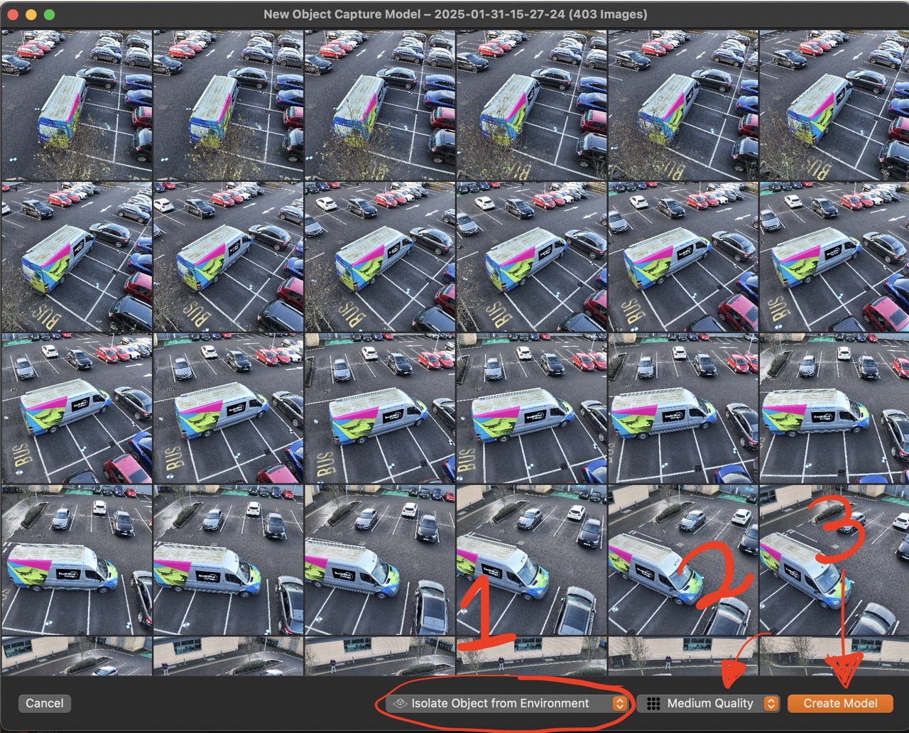 At this point, it really is one, two, three
1. Select Isolate Object from Environment. This will remove the background (for the most part)
2. Select the Quality – I set it to medium
3. Click Create Model
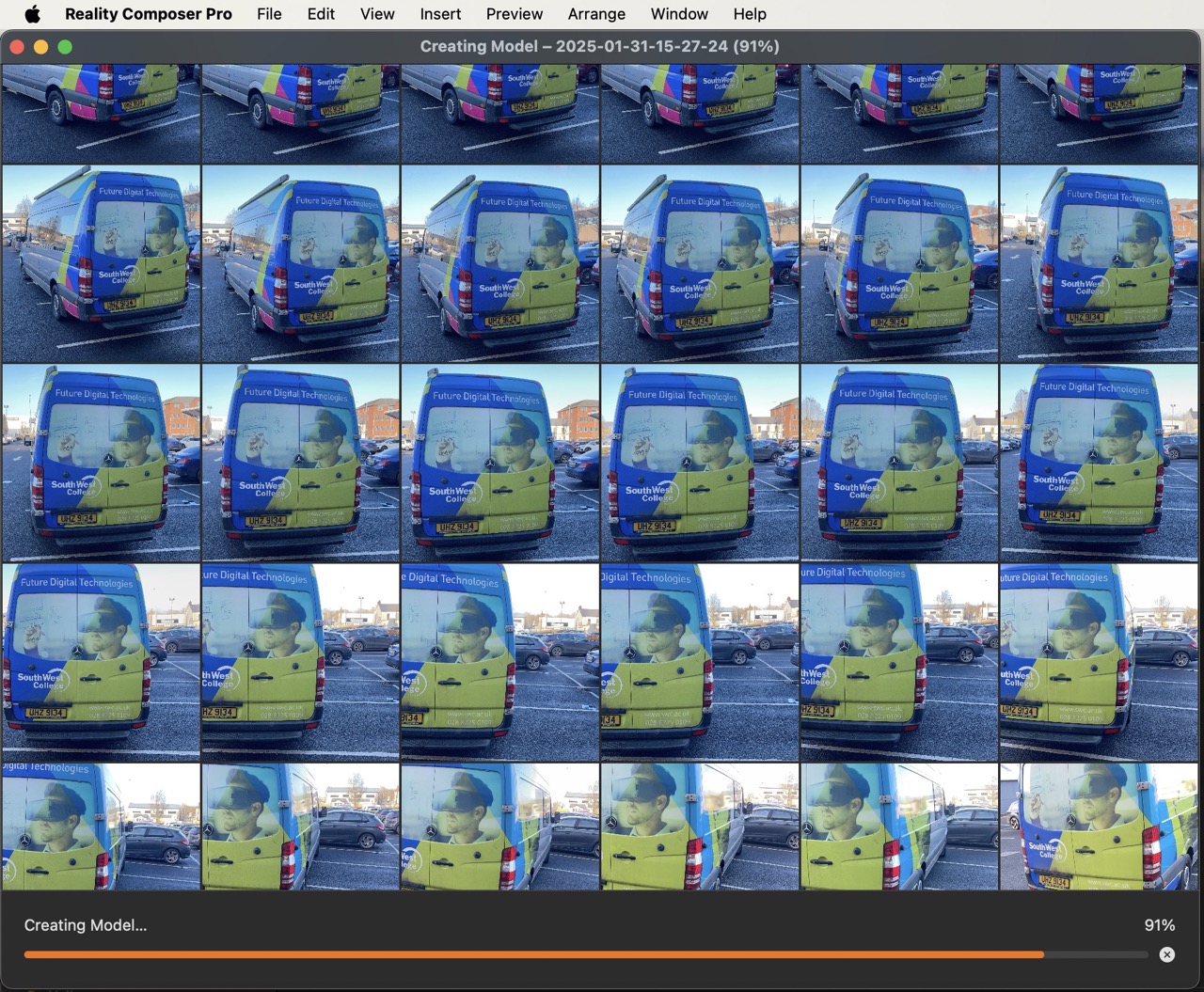
Sit back and wait for the magic to happen. (approx 1 hour in my case)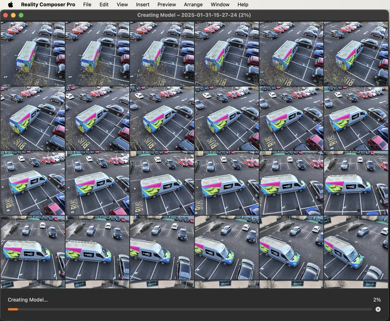 The status bar at the bottom will indicate progress.
 after an hour you should see the result – click export this exports a .usdz file format. To open this in Autodesk Fusion we need to convert it to .FBX or .OBJ we can use Blender for this. or other file format convertor.
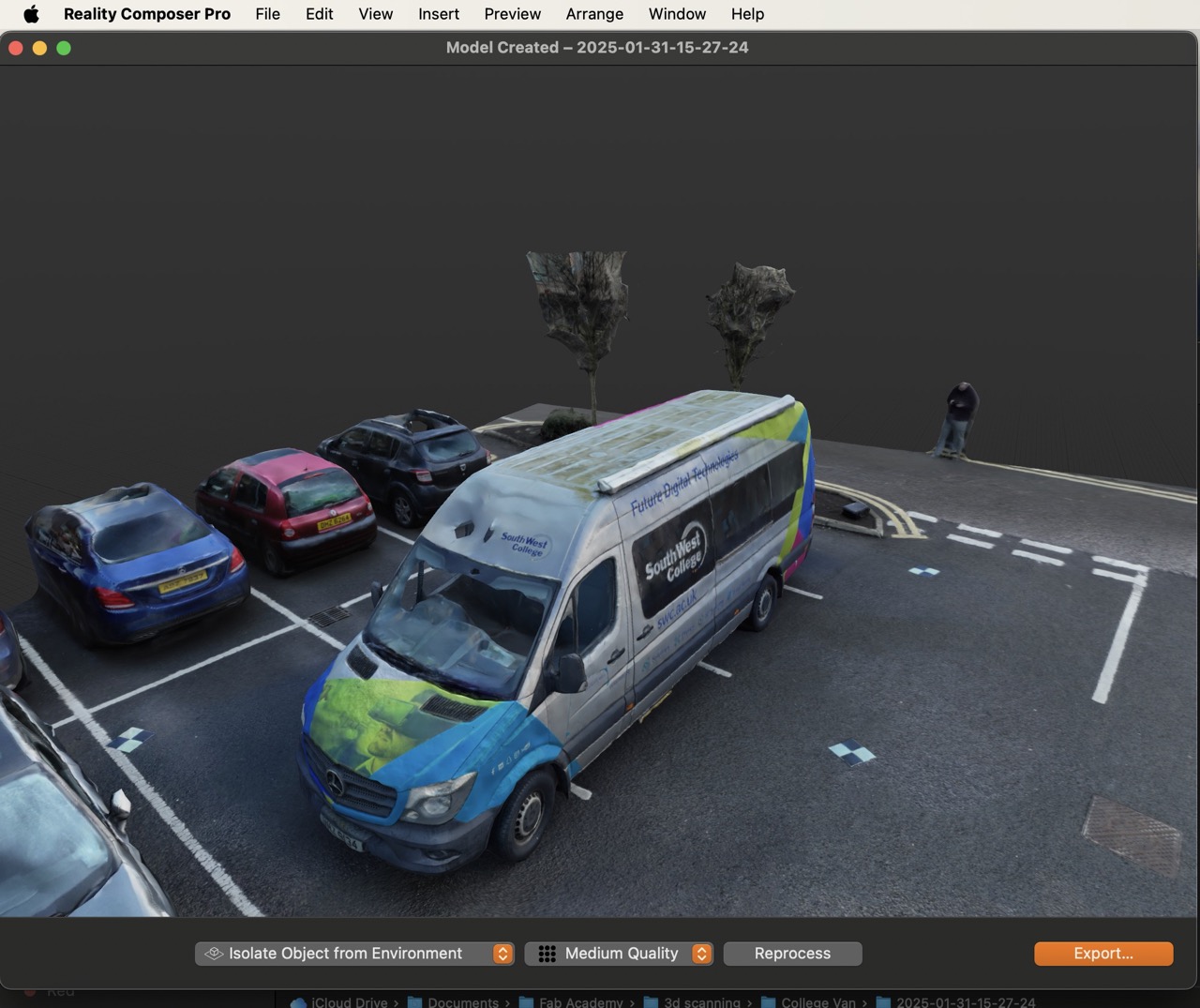
Conclusion
This is a very simple 3d model generation application that is free, and in my experience it gives decent results. When you compare it to something like Pix4D Matic the process of combining two different data sets is super easy if it's just a quick 3d representation you are looking to get. Most of the detail is in the texture map without is it's hard to tell where things are on the scan. It lacks the ability to have an area of interest so this did capture extra data from the surrounding cars, trees and even me flying the drone. My skills in Blender are lacking but we'll see how we go here. One thing I do need to figure out is how to remap the texture or remove the bits from the texture map that I don't need. This might reduce the file size a bit.Blender
Will add info here when i figure it out!!!
3d printing
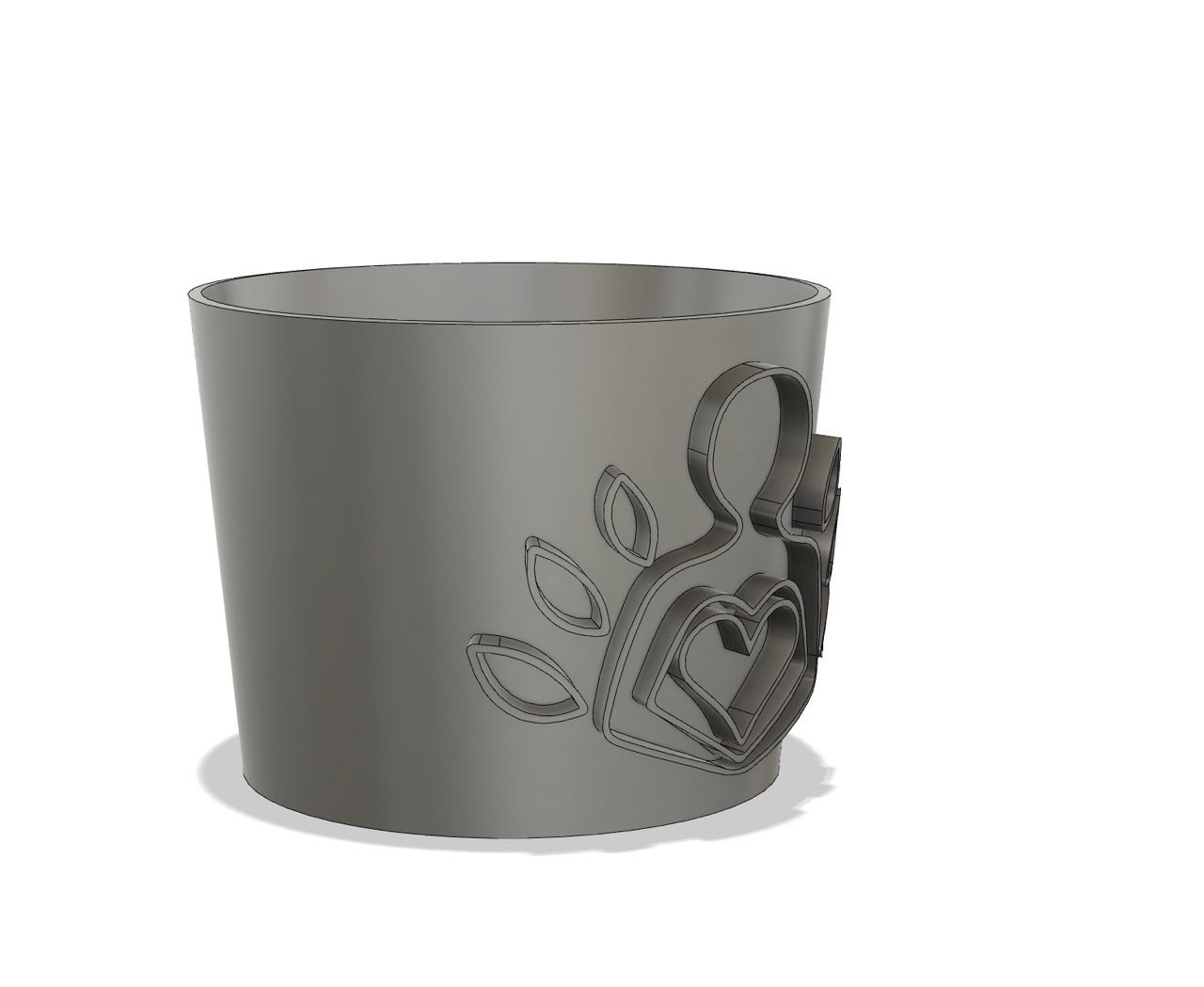
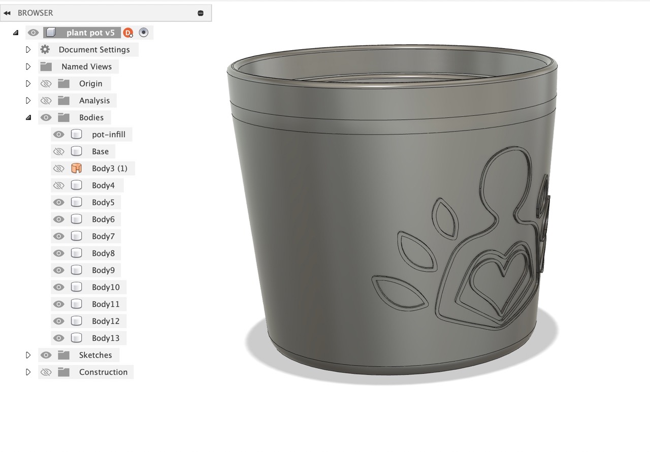
Modelled a simple plant pot in Autodesk Fusion
I decided to 3d print a flower pot this week using the infill pattern as part of the final result of the pot. This would be an air pot that would allow for better root development.
This was a fairly simple part to model in Autodesk Fusion. The pot can be personalised with text or other ornamental designs.
I would like for this part to be customised by the user and the part then be ready to download and print.
Once the part was created I exported it to the slicing software and then used the infill pattern in the slicing software to create the surface finish for the pot.
Section sketch profile was revolved. The upper lip and lower rim section was split from the main body to print these parts solid.
A custom design or text can be embossed onto the surface.
Sketch or image in this case was found online – this was to be produced as a gift and this specific design was wanted.
The image was image traced in Illustrator or Bitmap traced in Inkscape (right-click the image)
Set the tolerance and expand.
Invert the colour if needed to get an outline. Have a solid outline colour and set line weight to hairline.
With no infill colour.
Export this as SVG from Inkscape or DXF or SVG from Illustrator.
This can then be imported into Fusion to be embossed.
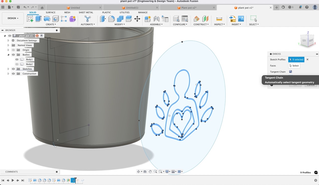 To emboss this I created a thin revolved wall approx. 5mm from the outer surface of the pot when revolving creates new body this will give us a surface to offset the design to as I want it to be a slight in eternally.
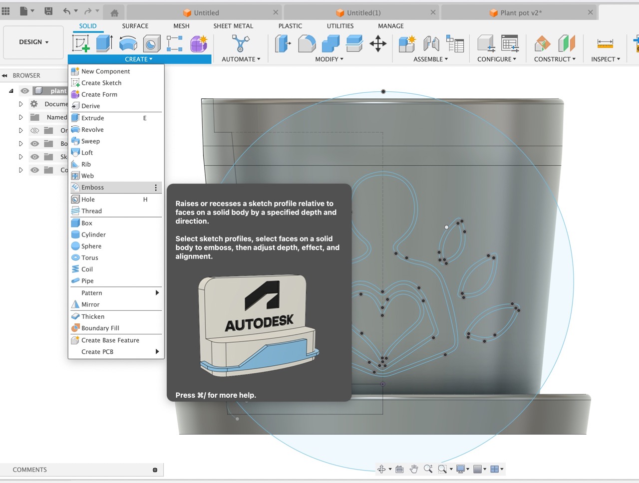 Emboss to this new body
 Then use the surface to split the parts form the revolved body used to emboss from.
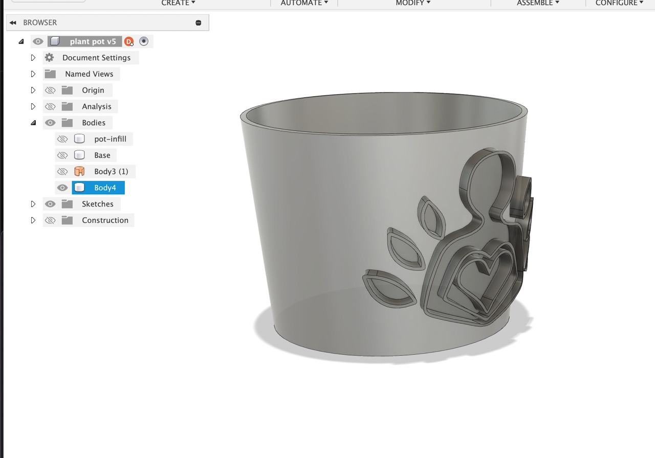 Split the upper section of the main plant pot and a rim around the base.
 This is mainly for aesthetics and strength.
Create a Boolean operation between the embossed parts and the main plant pot wall.
Keep tools
This is mainly for aesthetics and strength.
Create a Boolean operation between the embossed parts and the main plant pot wall.
Keep tools
 Turn off visibility on unwanted bodies that we do not want to export to the slicing software.
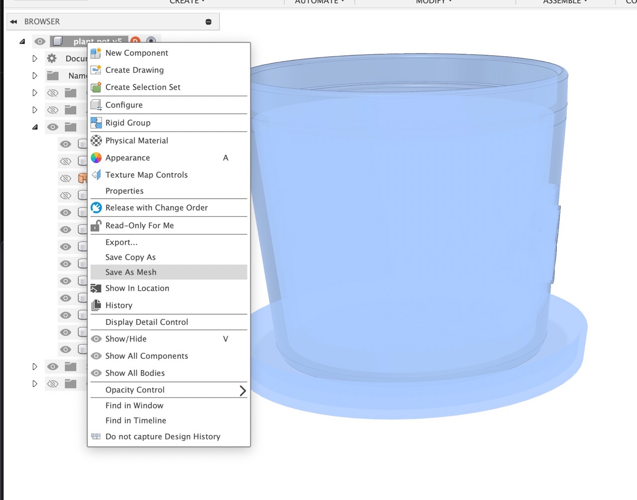
 Export mesh – few different ways to do this I just right-click the component in the browser. And select save as mesh.
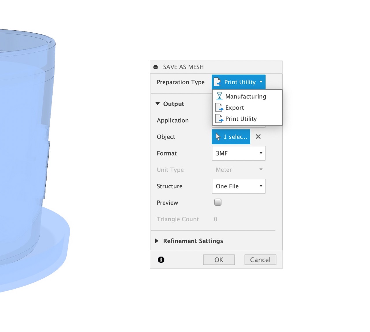
 Under preparation type select print utility
For me, that's Prusa slicer.
Select your desired file format and hit export.
Under preparation type select print utility
For me, that's Prusa slicer.
Select your desired file format and hit export.
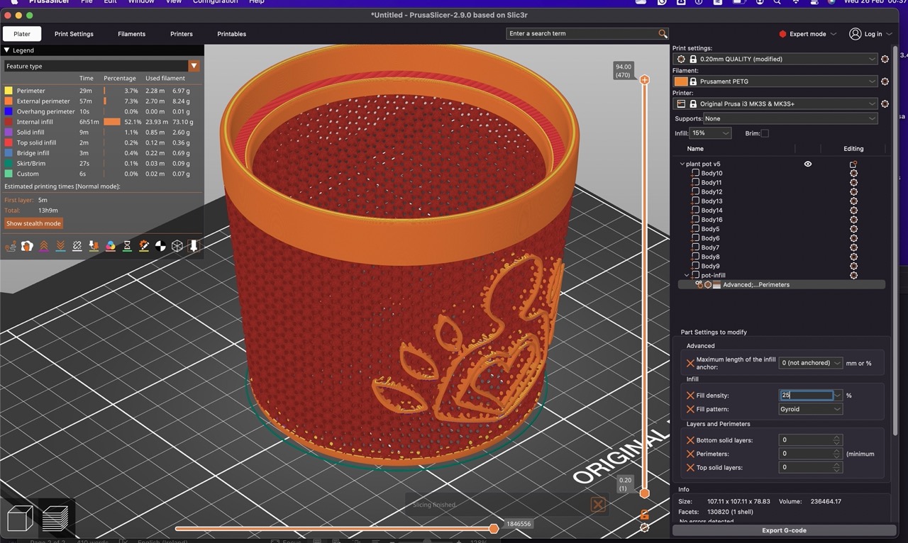
 It should open directly into Prusa Slicer
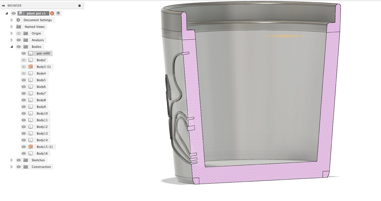
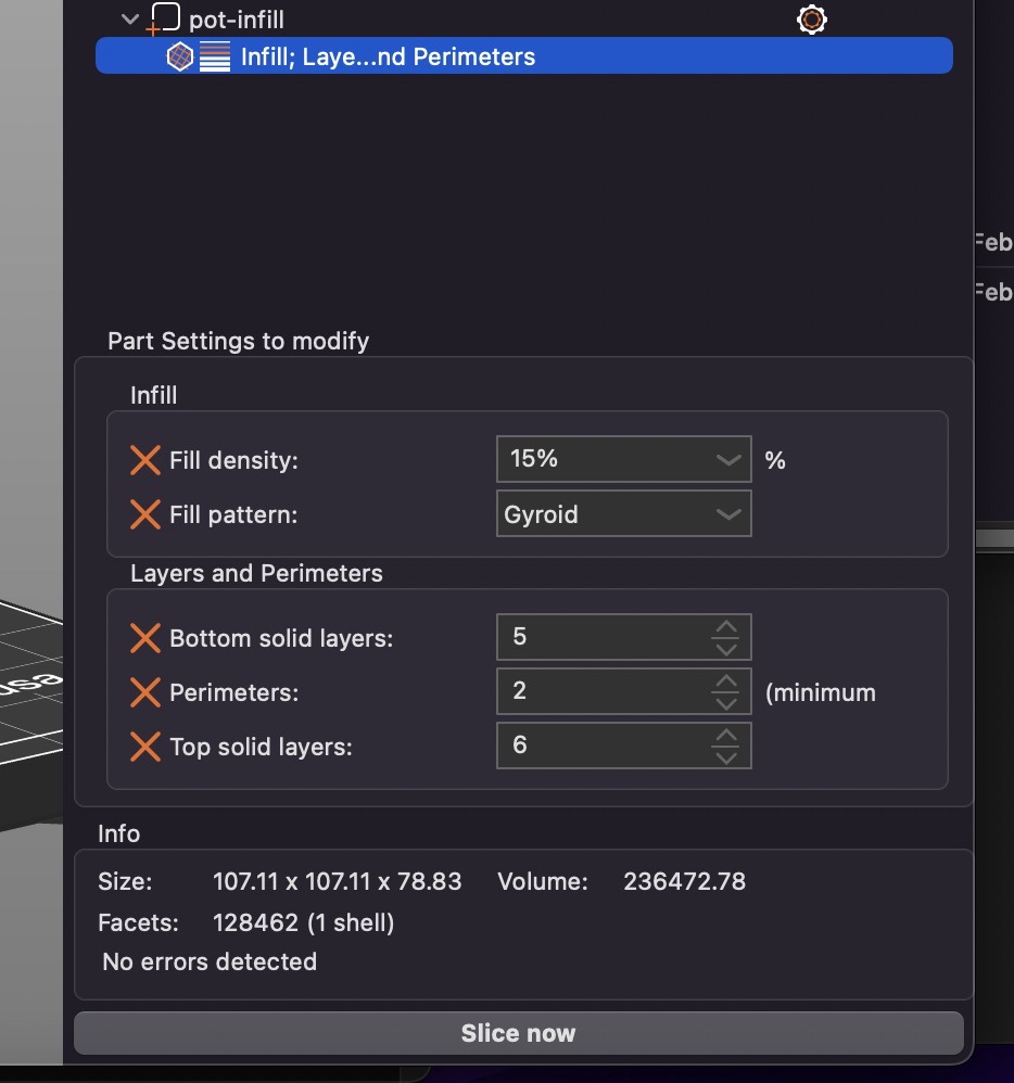
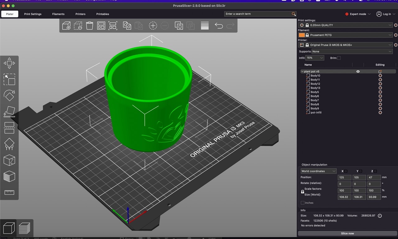 I renamed one body pot infill in fusion as this would be the only body I want to change in the Prusa slicer, setting the bottom solid layers, perimeters and top solid layers all to 0 and the infill to 17% gyroid ( I printed the first one at 25% this was too much. I'll print again and post an image of the final result later this week.
 Once happy export the g-code to the sd card and print on the printer making sure the correct filament is in the printer and the correct nozzle diameter is on the printer.
And let the printer work its magic.
Make sure the bed is clean and sitting on the printer correctly.
Once happy export the g-code to the sd card and print on the printer making sure the correct filament is in the printer and the correct nozzle diameter is on the printer.
And let the printer work its magic.
Make sure the bed is clean and sitting on the printer correctly.
 My first part took 17 hrs to complete.
Printing at .15mm layer height and 25%infill
The next one should be a fair bit quicker 9hrs with a .2mm layer height and 17% infill.
My first part took 17 hrs to complete.
Printing at .15mm layer height and 25%infill
The next one should be a fair bit quicker 9hrs with a .2mm layer height and 17% infill.
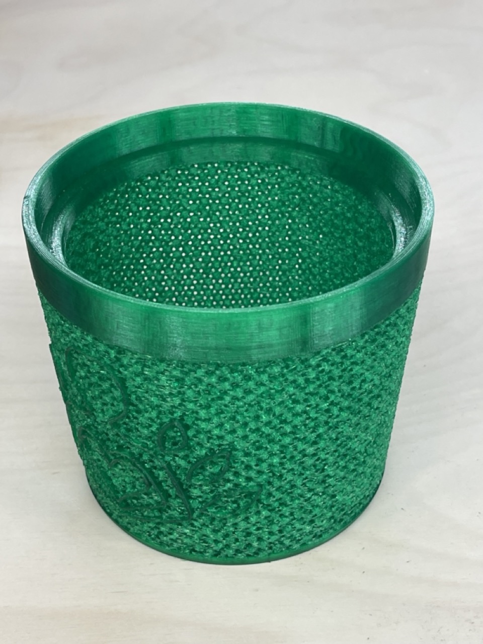
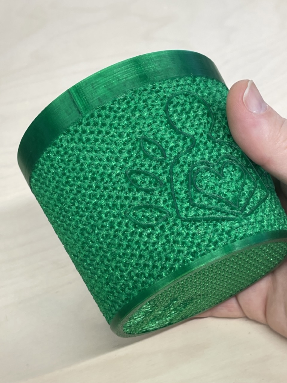
 below is the first part from the printer
 See CAD files and gcode in link below.
On a side note, I did find an online editor that allows you to embed and editio on your website - see below
See CAD files and gcode in link below.
On a side note, I did find an online editor that allows you to embed and editio on your website - see below
Issues I've encountered
AGHHHHH
Learning Outcomes
A lot about low end scanning with photogrammetery and 3d printing. Some issues with bed athesion, 3d scanning capabilities
Digital Files
Week 05 digital filesOther things this week
check out beegraphy an online paratmetric modeler, very similar to grasshopper in rhino it allows you to embed files on your website this is a very basic folwer pot that was was printing this week (i didnt use this used fusion but came across this on sunday night when i was ment to be pusing updates to my website... me going off on tngents again