Week 4. Embedded Programming
Lets learn how to control the world around us with Embedded Programming….
Group Assignment (link):
Demonstrate and compare the toolchains and development workflows for available embedded architectures
Individual Assignment:
Browse through the data sheet for your microcontroller.
Write a program for a microcontroller,
and simulate its operation,
to interact (with local input &/or output devices)
and communicate (with remote wired or wireless connections)
extra credit: test it on a development board
extra credit: try different languages &/or development environments
Useful Links
Seed Studio XIAO Expansion Board
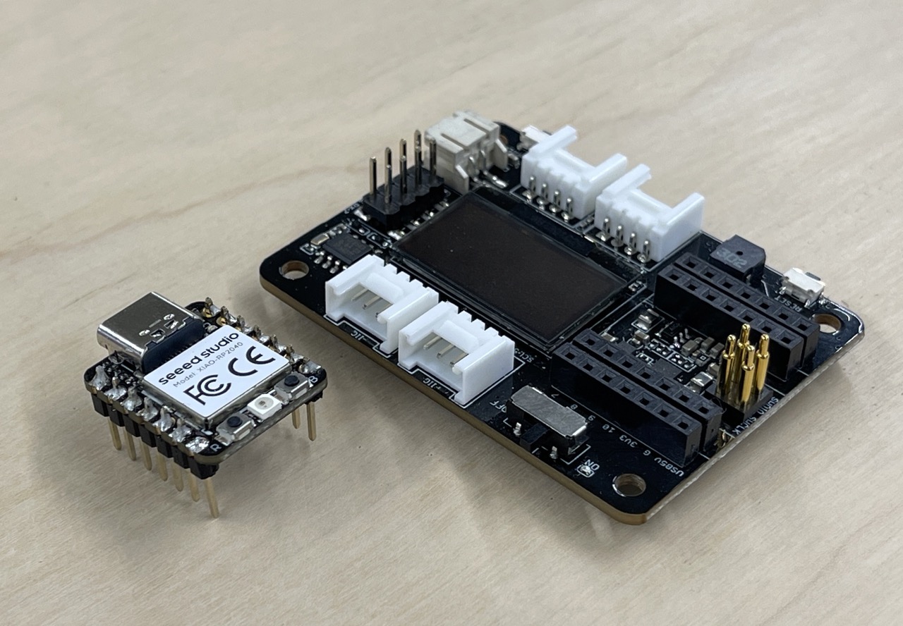
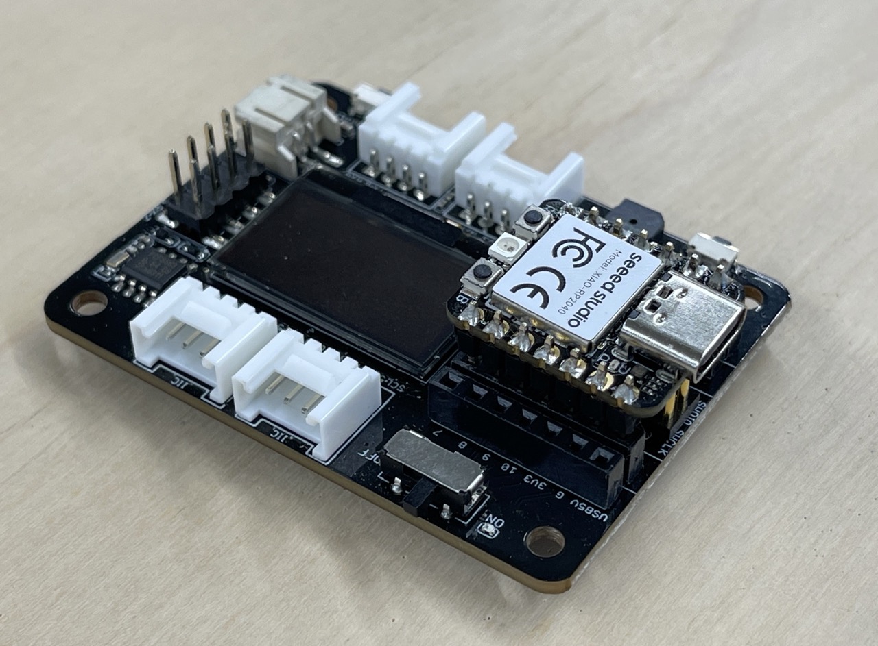
Seeed XIAO RP2040 & Seeed Studio XIAO Expansion Board
I was given the Seeed XIAO RP 2040 and the Seeed Studio XIAO Expansion Board to play with this week.
You can see how we set up arduino IDE and install the libraries for the XIAO RP2040 as part of our group assignment Link here.
I was concentrating on the Arduion IDE however I would also like to get looking at Python as well as I have a feeling I might be programming my final project in python. But for now I will continue with Arduino IDE.
This week was particularly daunting with many issues encountered. But preservice overcame and we managed to get things to work.
I'm still not sure if this is the correct board for my final project yet as I still don't fully understand what will be need from a microcontroller for the project needs. But this is a good a place to start as any for a bit of lite reading ….
600 page + of data sheet…. 99% of which went straight over my head!! But here are the key bits of info that we need to take from the RP2040 data sheet. link to the PDF .
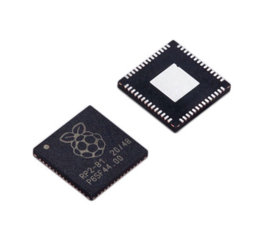
So this is the chip we are looking at the PR2040
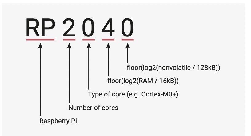
Why is it called the RP2040 – I guess this is why we look into the data sheet and this image explains why.
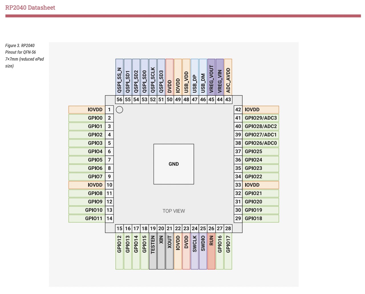
The above images shoes us the pinpout from the RP2040 Data Sheet – to be honest this is all the information I took from the data sheet to date – I did glance through the data sheet but it made little sense to me.
of curse at this stage we will not be using the RP2040 in it's raw state – perhaps later - but for now we will use it in the Seeed Studio XIAO RP2040 and it's Expansion Board.
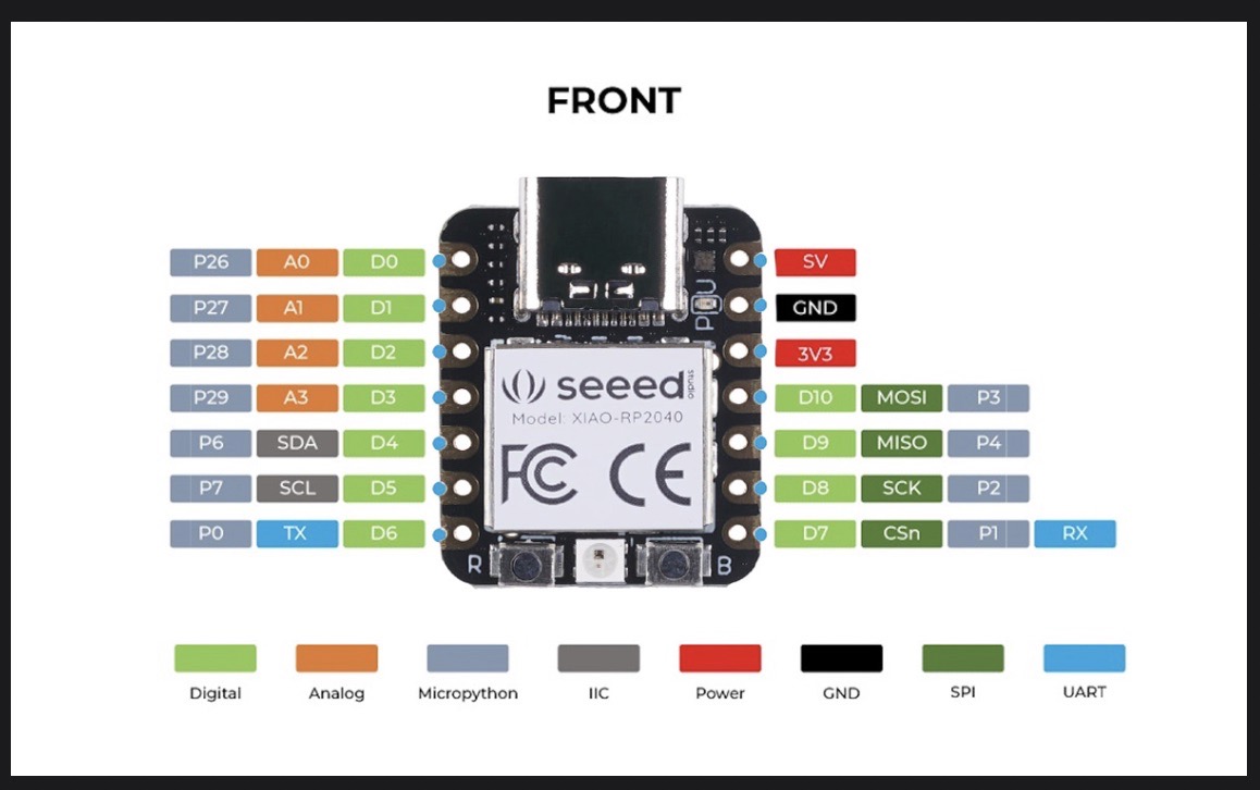
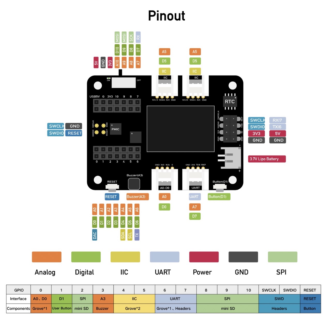
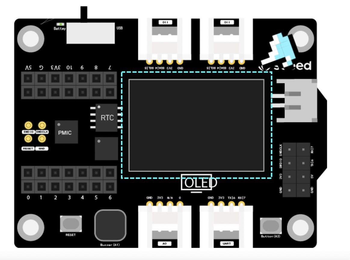
This image shows us the pinout for the Seeed Studio XIAO RP2040 and the Seed Studio XIAO Expansion Board.
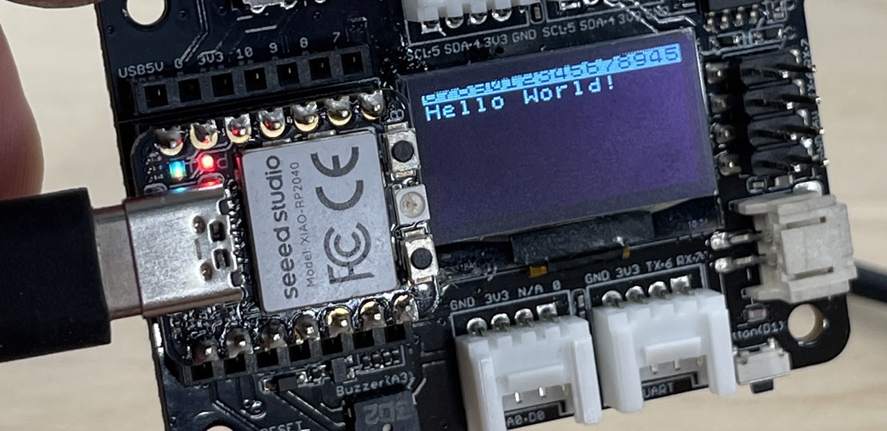
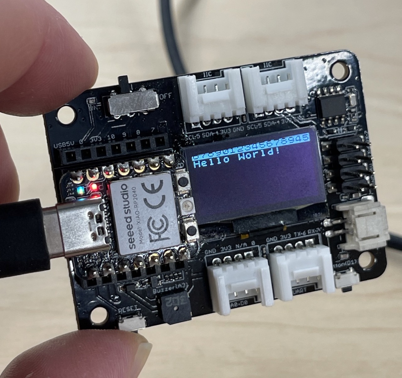
After creating the push button code, as part of the group assignment, I wanted to use the onboard display.
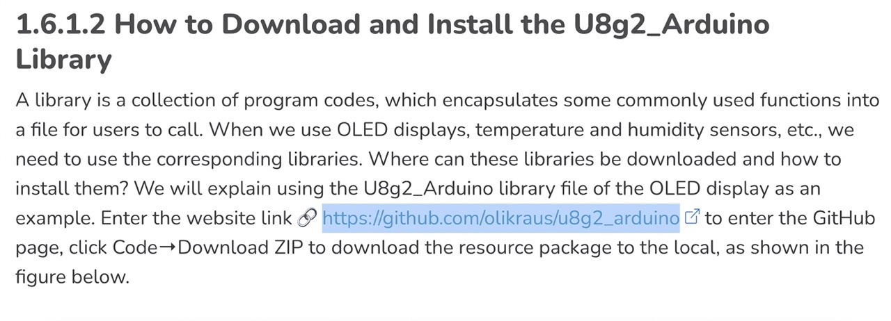
Following the tutorial in the online ebook – canpter 1.6 displaying "hello world" on OLED
link to the tutorial.I downloaded the necessary library to control the OLED display by following the link
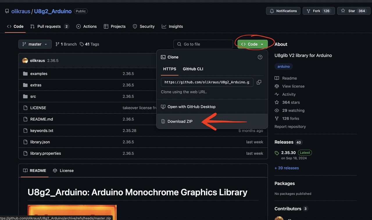
Download the code, click the green code button and click Download ZIP.
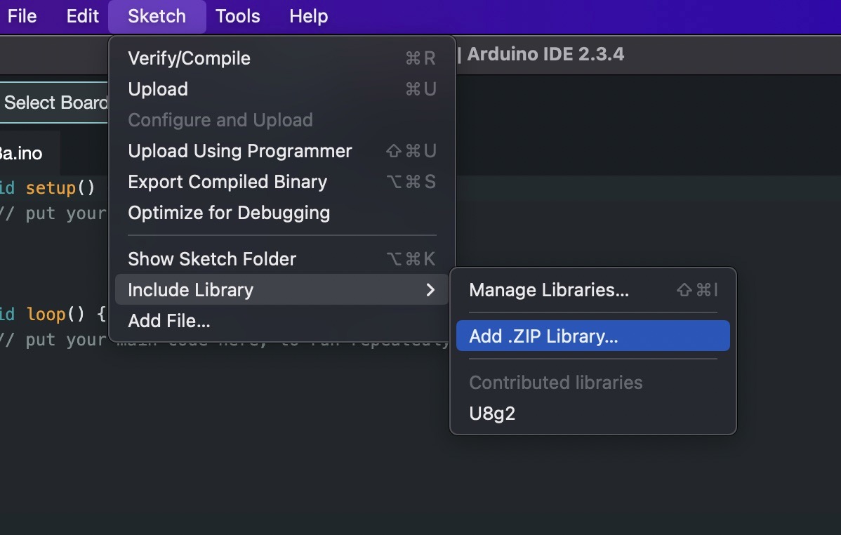
In the Arduino IDE go to Sketch> Include library> Add .ZIP Library… navigate to the download folder where and select the downloaded file.
I used the below code in the Arduino IDE to say "Hello World!"
Copy the code
									#include //Use U8x8 library file
									U8X8_SSD1306_128X64_NONAME_HW_I2C u8x8(/* reset=*/ U8X8_PIN_NONE);
									//Set the constructor, define the display type, controller, RAM buffer size, and communication protocol, generally determine according to the used display model

									void setup(void) {
										u8x8.begin();//Initialize u8x8 library
										u8x8.setFlipMode(1);//Flip the display 180 degrees, generally numbers 0 and 1
									}

									void loop(void) {
										u8x8.setFont(u8x8_font_8x13_1x2_r);//Define u8x8 font
										u8x8.setCursor(0, 0);//Set the position of the drawing cursor
										u8x8.print("Hello World!");//Draw content on OLED: Hello World!
									}
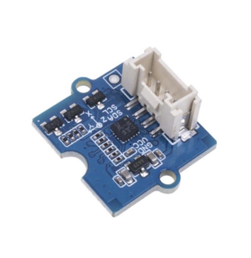
It's time to go a little further – I want to use the 3axis accelerometer and measure what's happening. – I will be using at least one of these in my final project.
Again I'm using the code from the eBook chapter 2.4 Rhythmic Dance with a Triaxial Accelerometer.
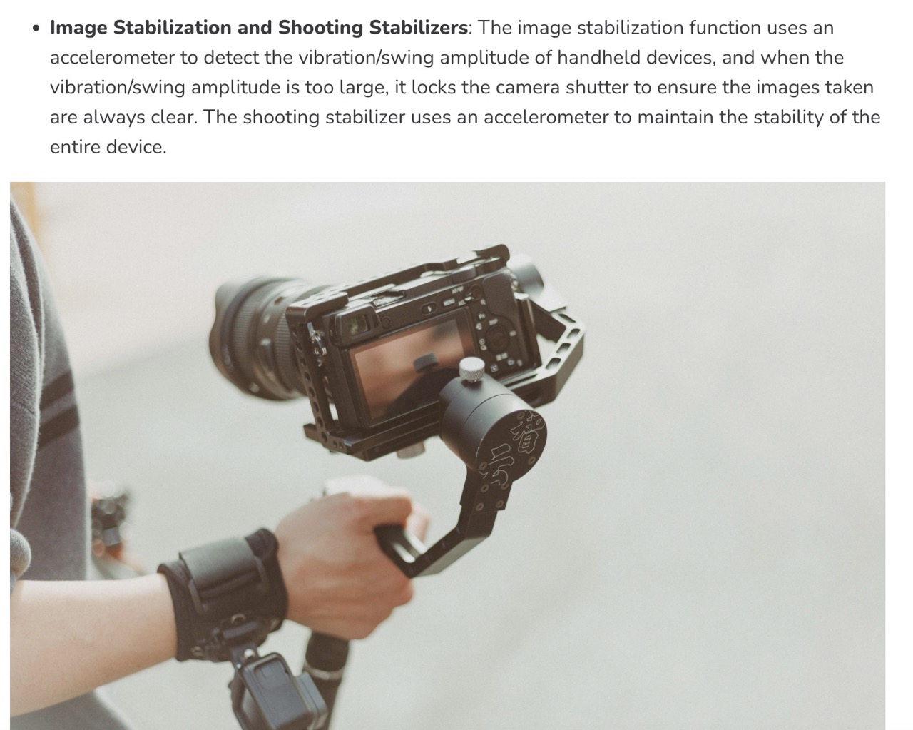
link to the tutorial.This chapter gives some insight into the accelerometer and what its used for – here we find they can be used for steady cam or motion stabilisation- which is what I'm looking to use it for.
Again we will need to add some libraries to use the accelerometer in the kit . follow the link and follllow the same procedure we used for the OLED screen. link to the tutorial.
Download .zip folder and install library from zip in the Arduino IDE
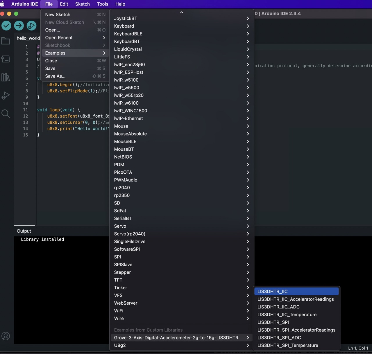
When this is installed we can now open an example code file (scroll down the bottom) File>Examples>Grove-3-Axis-Digital-Accelerometer-2g-to-16g-LIS3DHTR>LIS3DHTR_IIC.
We need to change some things in this sample code – download the files at the bottom of this page it had all the necessary code changes.
Main changes are baud rate of serial monitor should be 9600
And delete the // on //LIS.begin(WIRE, 0x19); //IIC init
And add // to LIS.begin(WIRE); //IIC init dafault :0x18
Verify the code if all looks good upload to the board.
You will then need to open serial monitor tools>serial monitor
This will show readings from the accelerometer in X,Y & Z direction and also give us a temperature reading.
See video below….
Issues I've encountered
AGHHHHH
After sucesfully running pusing programme after installing Arduino IDE and installing necessary libraries etc. after leaving the computer for a day or two and trying to compile the same code again I was getting errors .
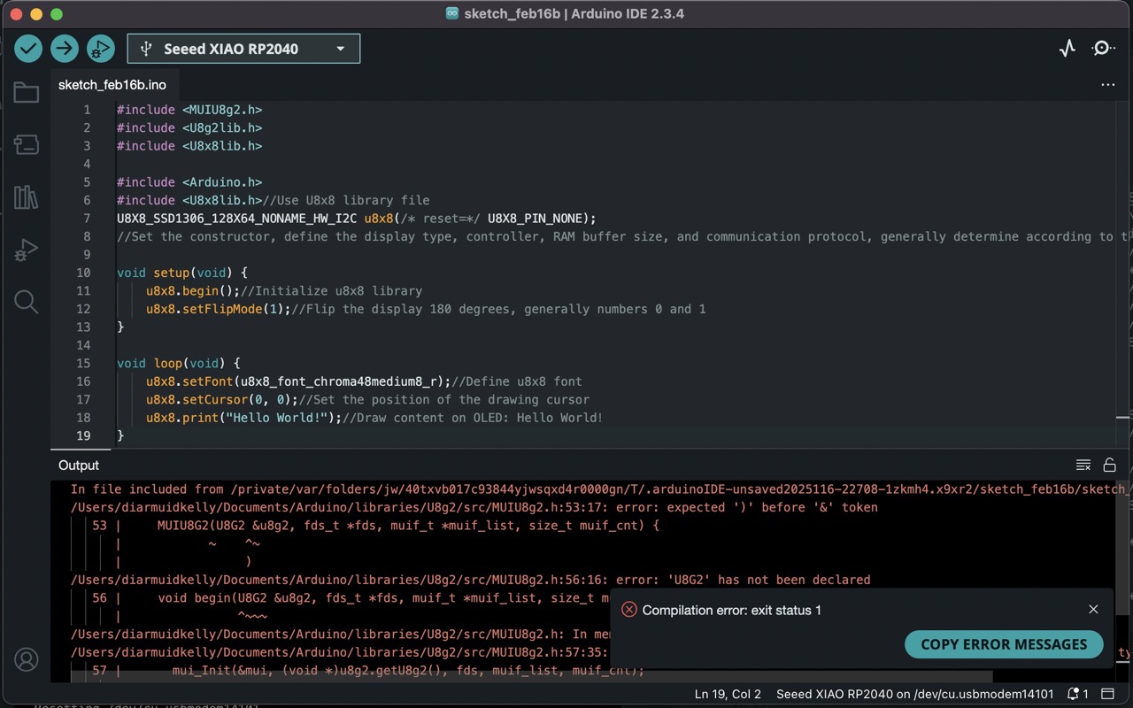
Couldn't compile the code – I was getting errors.
I'm thinking it's because the documents folder is part of iCloud and pushing files to the cloud these files my not be on my computer when it comes to complying later. However I cant be sure about this. To overcome the problem I had to delete the Arduino folder in the documents folder and also deleted the Arduino programme and reinstalled all including the boards and libraries. For now I can complying works and managed to get files pushed to the board.Learning Outcomes
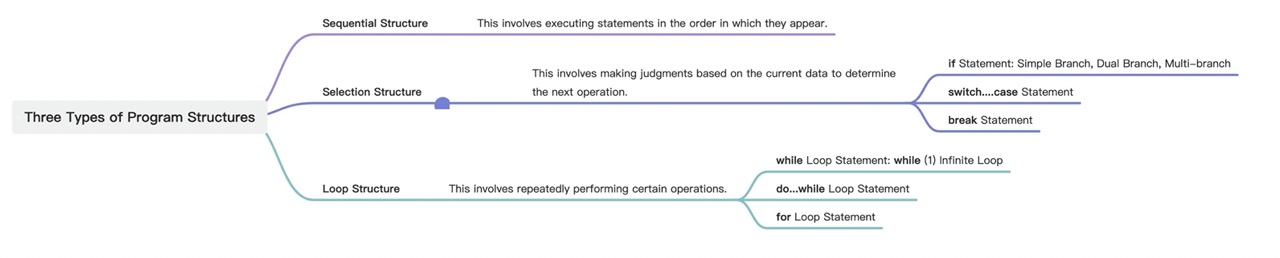
Code structure and how the types of flow required - I will need to explore more of this but this week has given me a good grounding.
I have a good grounding in the Arduino IDE and have a good understanding of the code structure and how the types of flow required.