Week 3. Computer-Controlled Cutting
Lets get practical!!
Group assignment: (link here)
Do your lab's safety training
Characterize your lasercutter's focus, power, speed, rate, kerf, joint clearance and types.
Document your work to the group work page and reflect on your individual page what you learned.
Individual assignment:
Design, lasercut, and document a parametric construction kit, accounting for the lasercutter kerf, which can be assembled in multiple ways.
Cut something on the vinyl cutter.
Learning outcomes
Demonstrate and describe parametric 2D modelling processes.
Identify and explain processes involved in using the laser cutter.
Develop, evaluate and construct a parametric construction kit.
Usefull Links
Vinyl Cutting
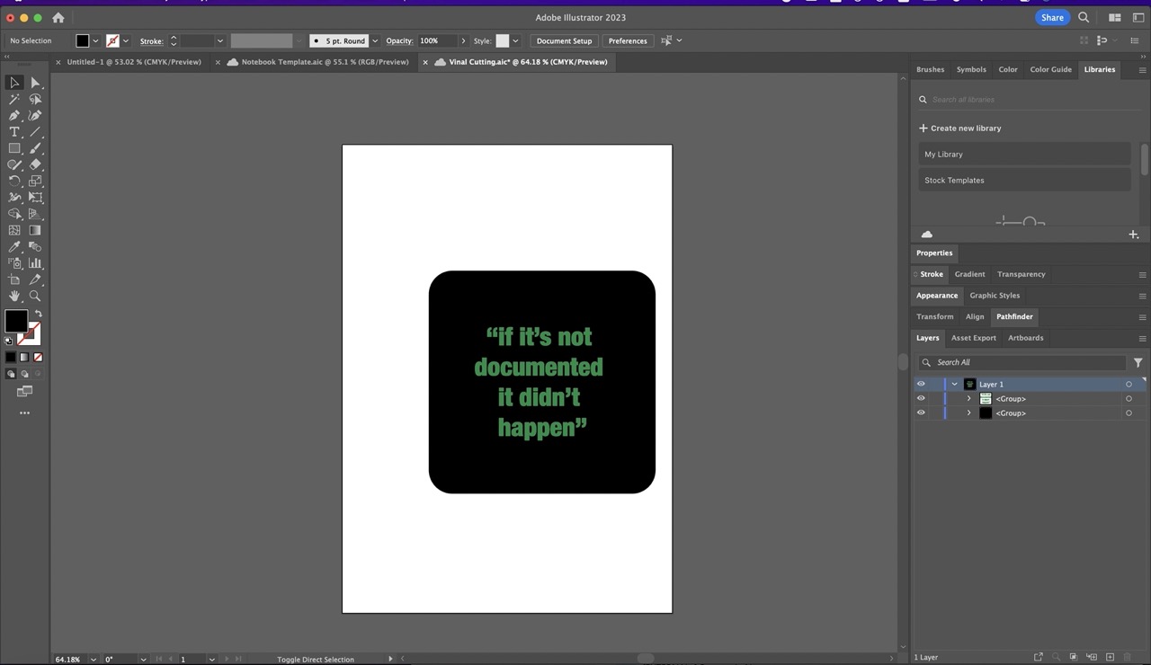
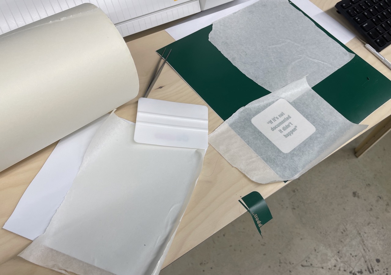
I created a document in Adobe Illustrator to the size I wanted. This contained text and a background. The intention was to have a square with the Fab Academy mantra "if it's not documented it didn't happen" for my Fab Academy notebook.
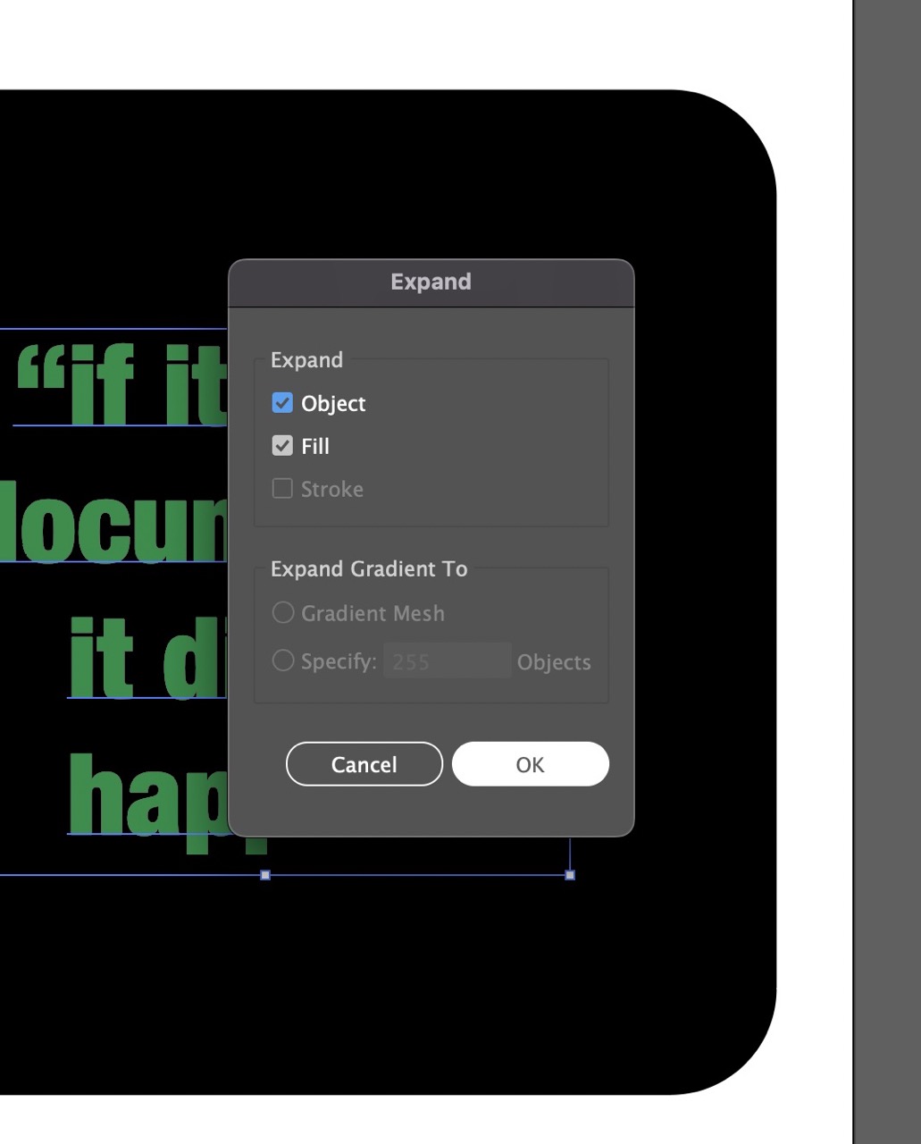
We need to outline the text; this will allow us to move the document to another computer that might not have the font. To do this we go >object >expand in Illustrator.
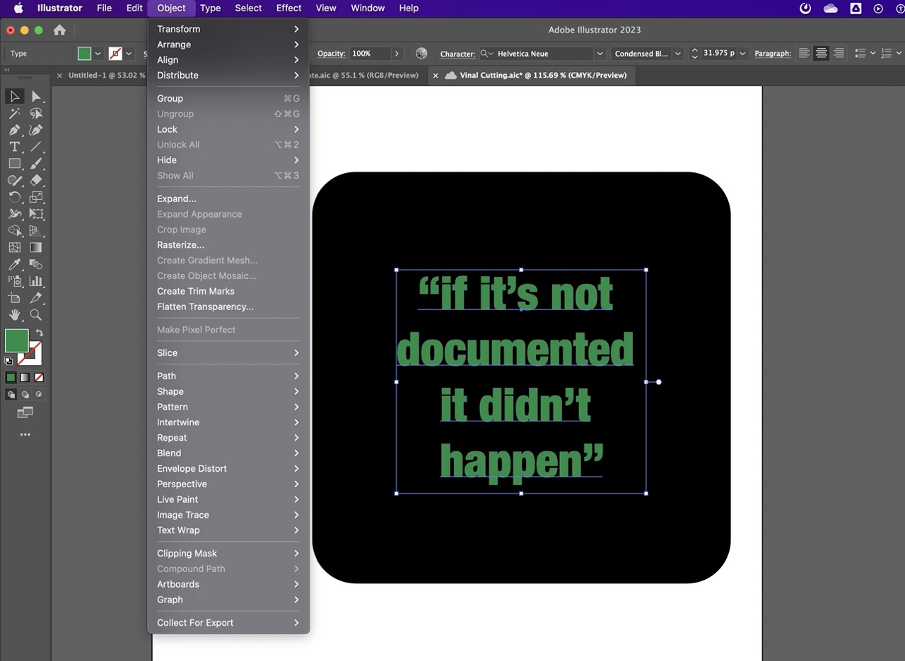
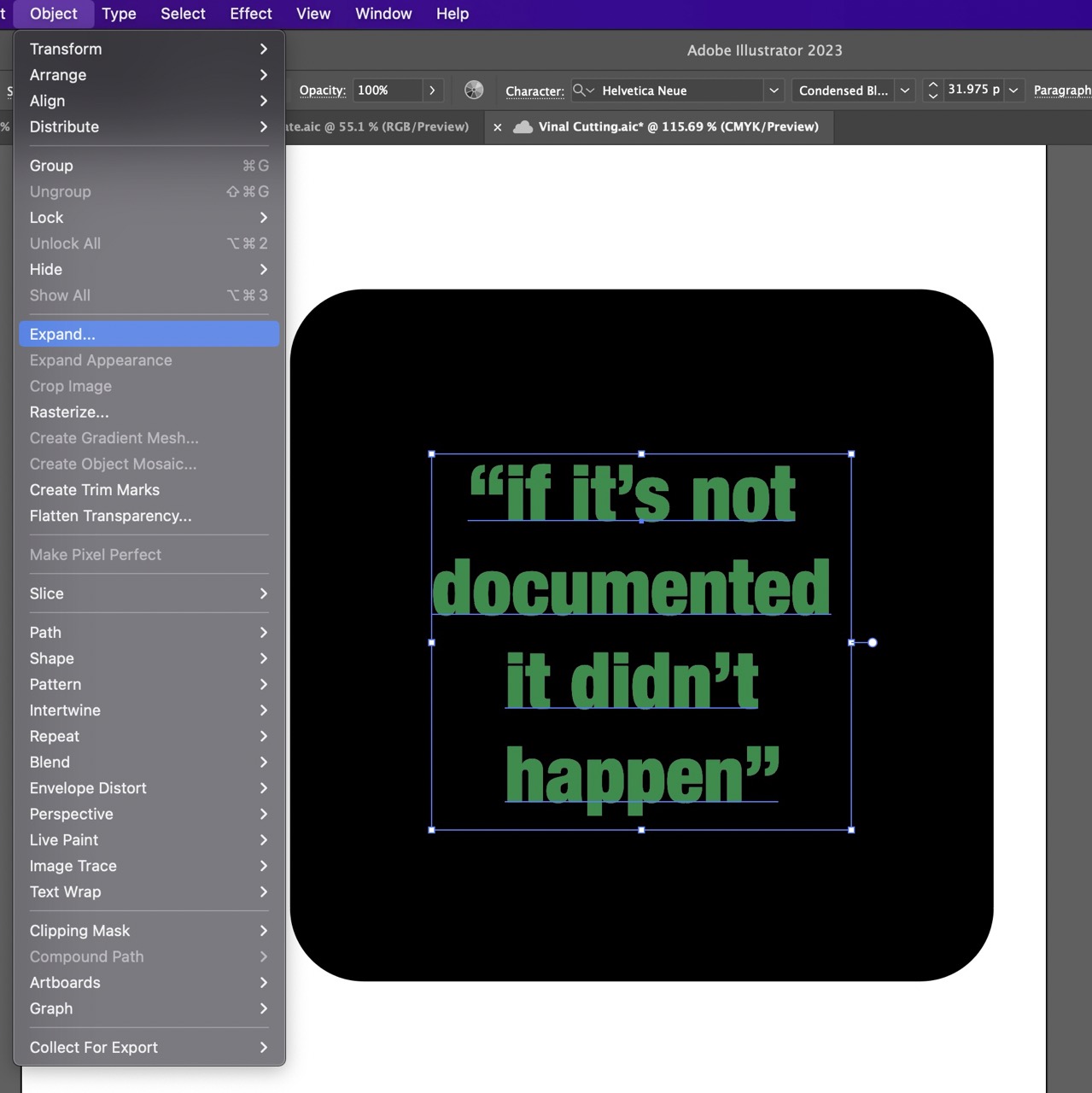
Ensure object and fill are selected in the dialogue box. Click OK.
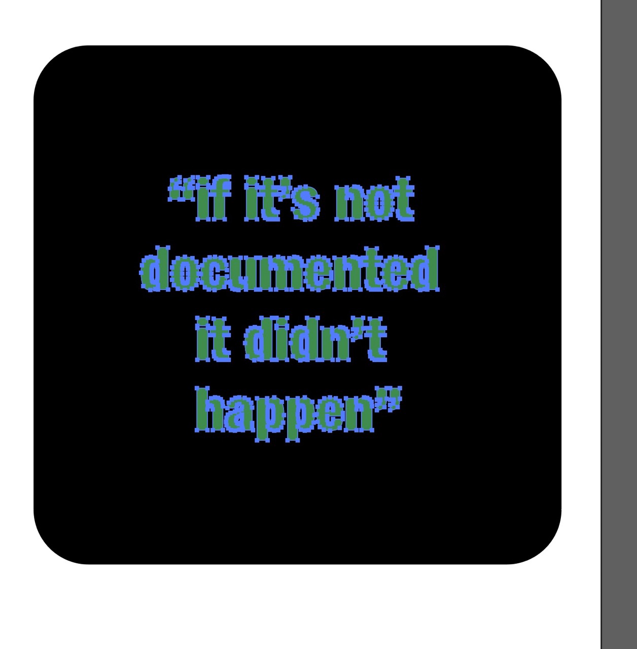
You should see the text outlined like this when selected.
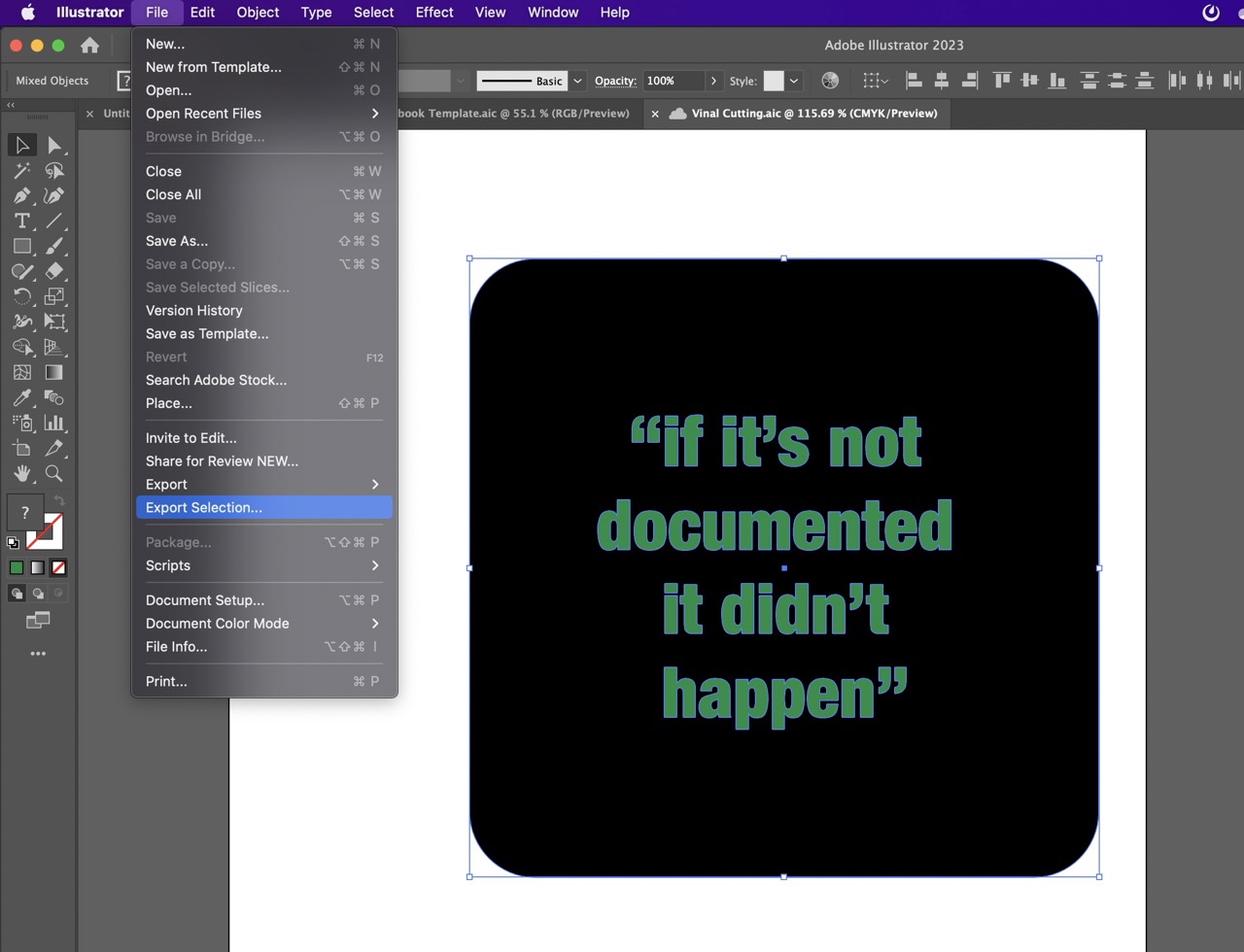
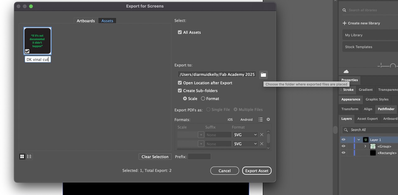
We are now ready to export we can box select what we need to export >File >Export Selection
In the dialogue box we can rename the "Asset 2" in my case to the desired file name.
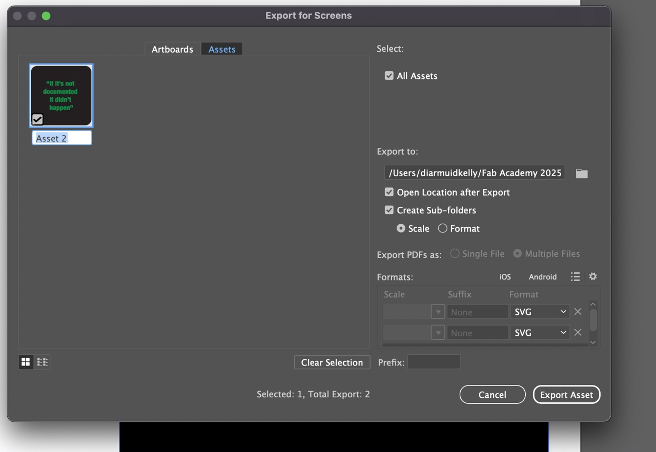
We can also select where we want the exported file to be saved. Ensure you select SVG and the file format, it is also possible to select other formats if you need them at this stage it should export them all at this stage. I just need SVG format.
We can now take this to the computer connected to the vinyl cutter. In the Creative Spark Fab Lab that computer is running Inkscape which is why we exported in SVG. FYI - It is possible to cut from Illustrator if Roland Cut Studio plugin is installed.
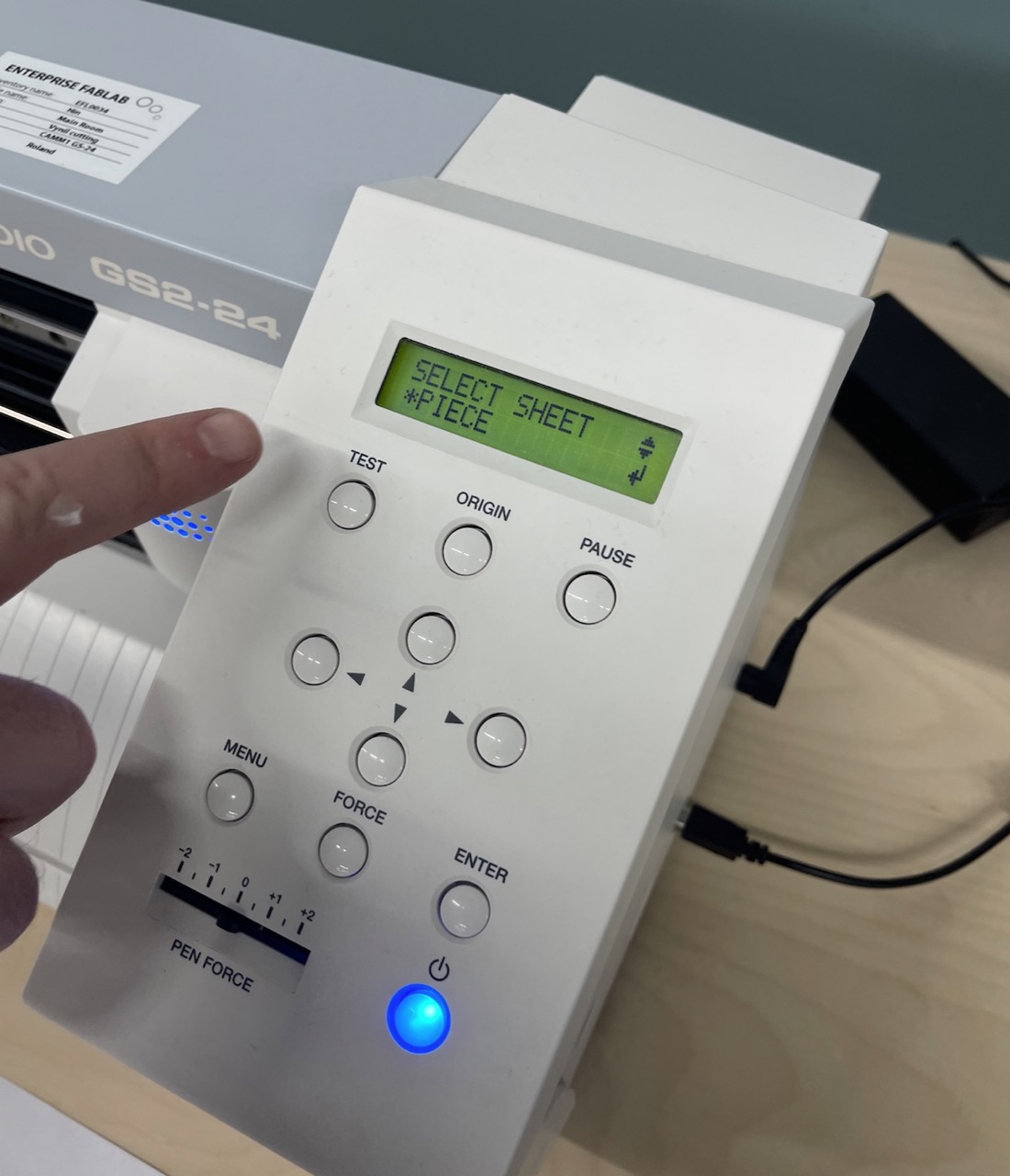
Time to set up the vinyl cutter – in this case it is the Roland GS2-24. We are going to use a piece to cut the part from. In the cutter menu select piece and press enter.
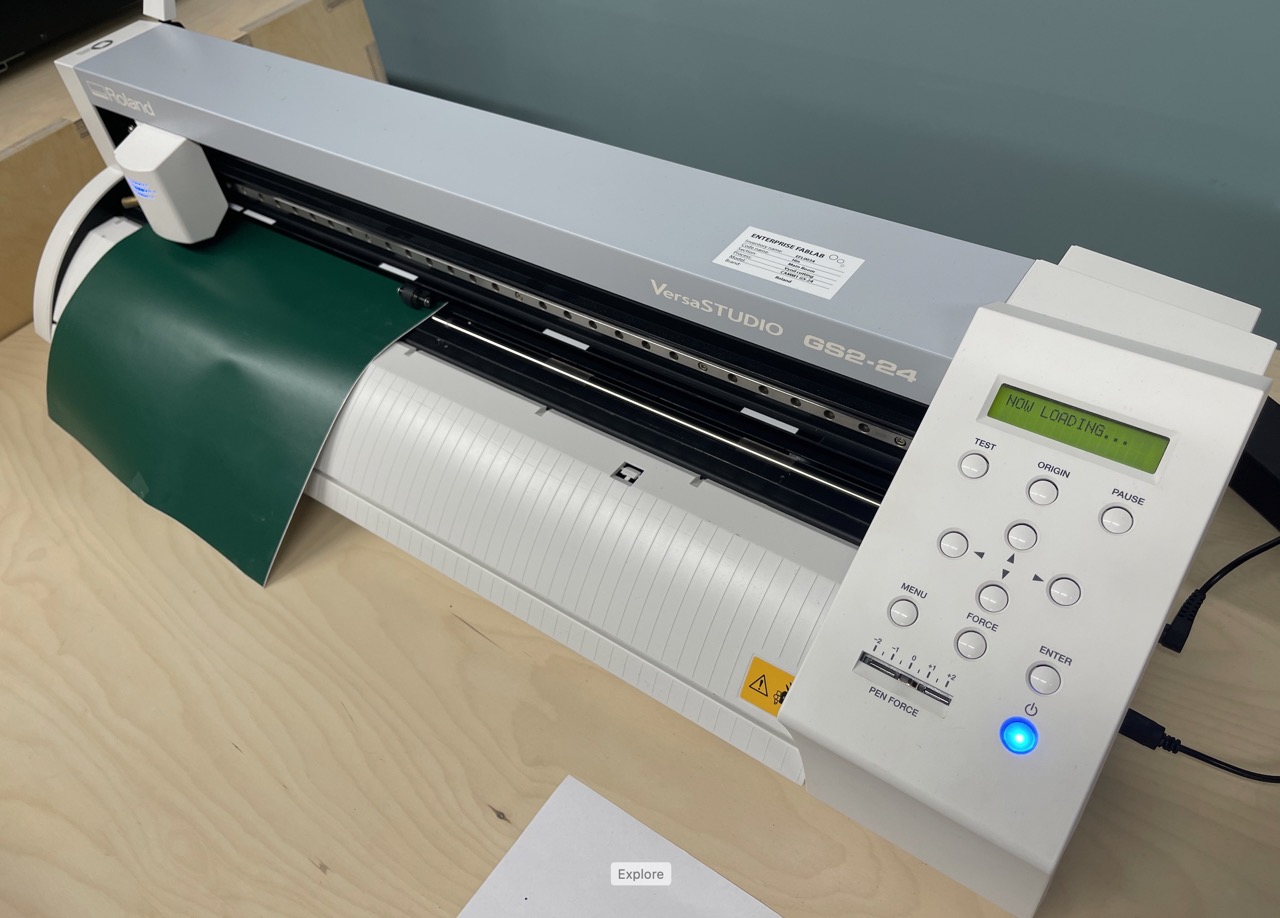
The vinyl cutter will measure the piece size.
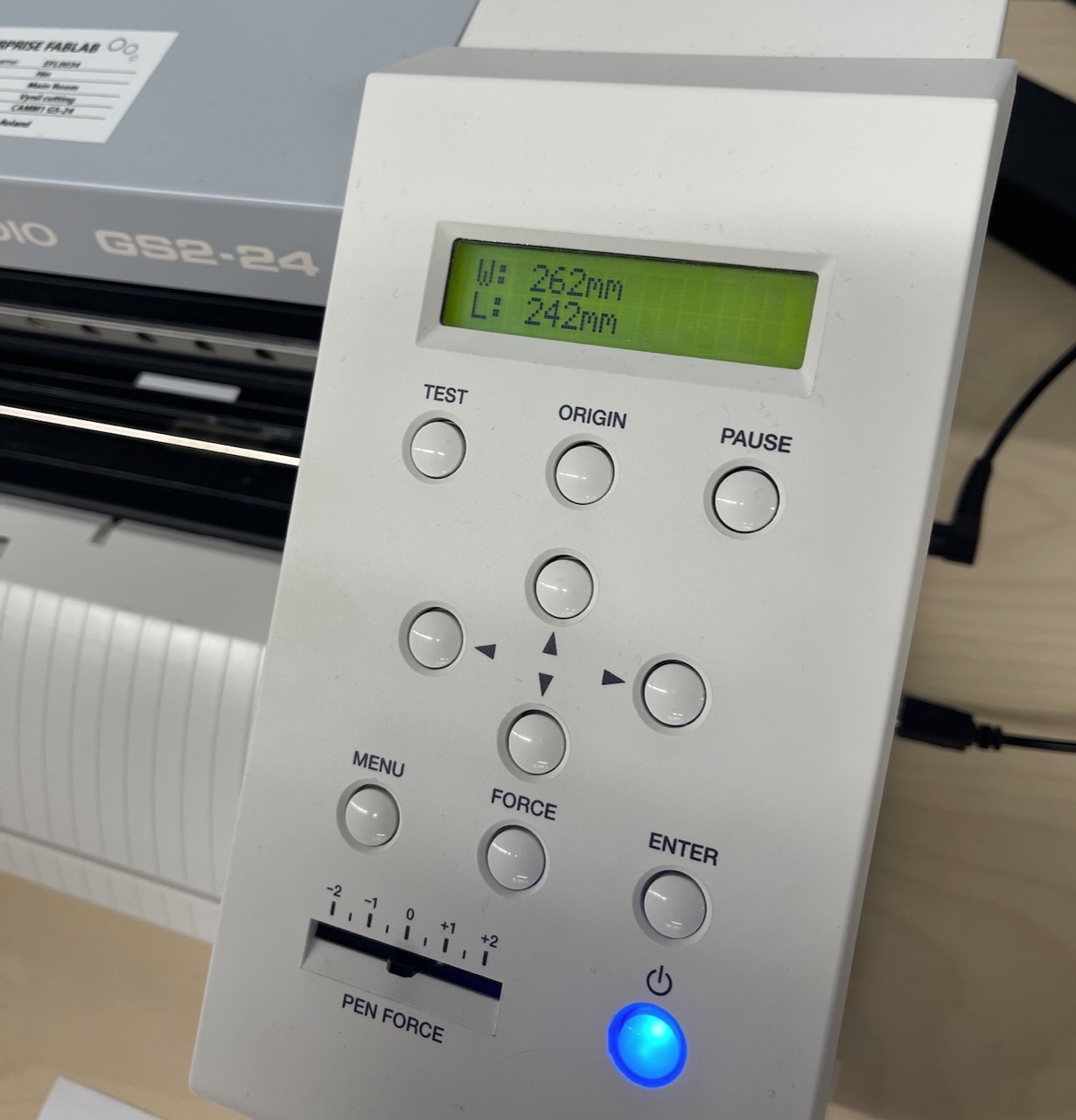
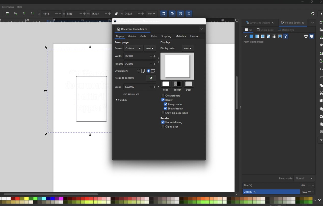
We will use this dimension to set the artboard size in Inkscape.
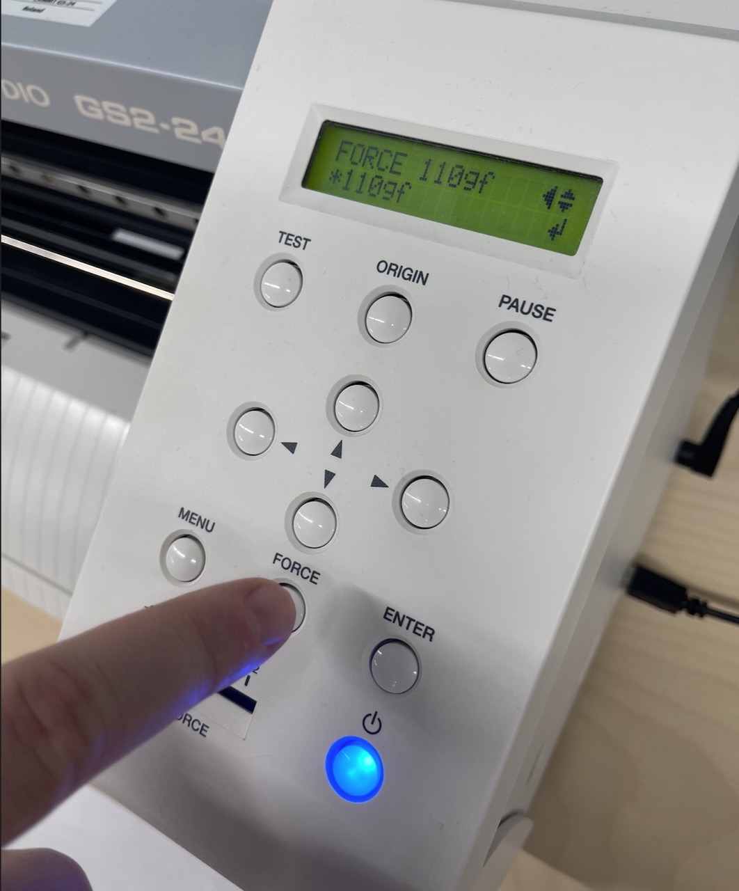
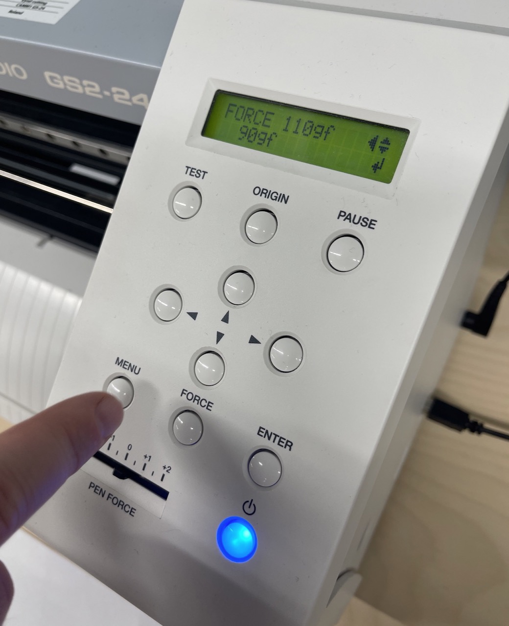
Set the Force – from past experience using this material and blade type it should be set to 90gf.
Import the document into Inkscape. Set the artboard size to the same as what was measured on the vinyl cutter
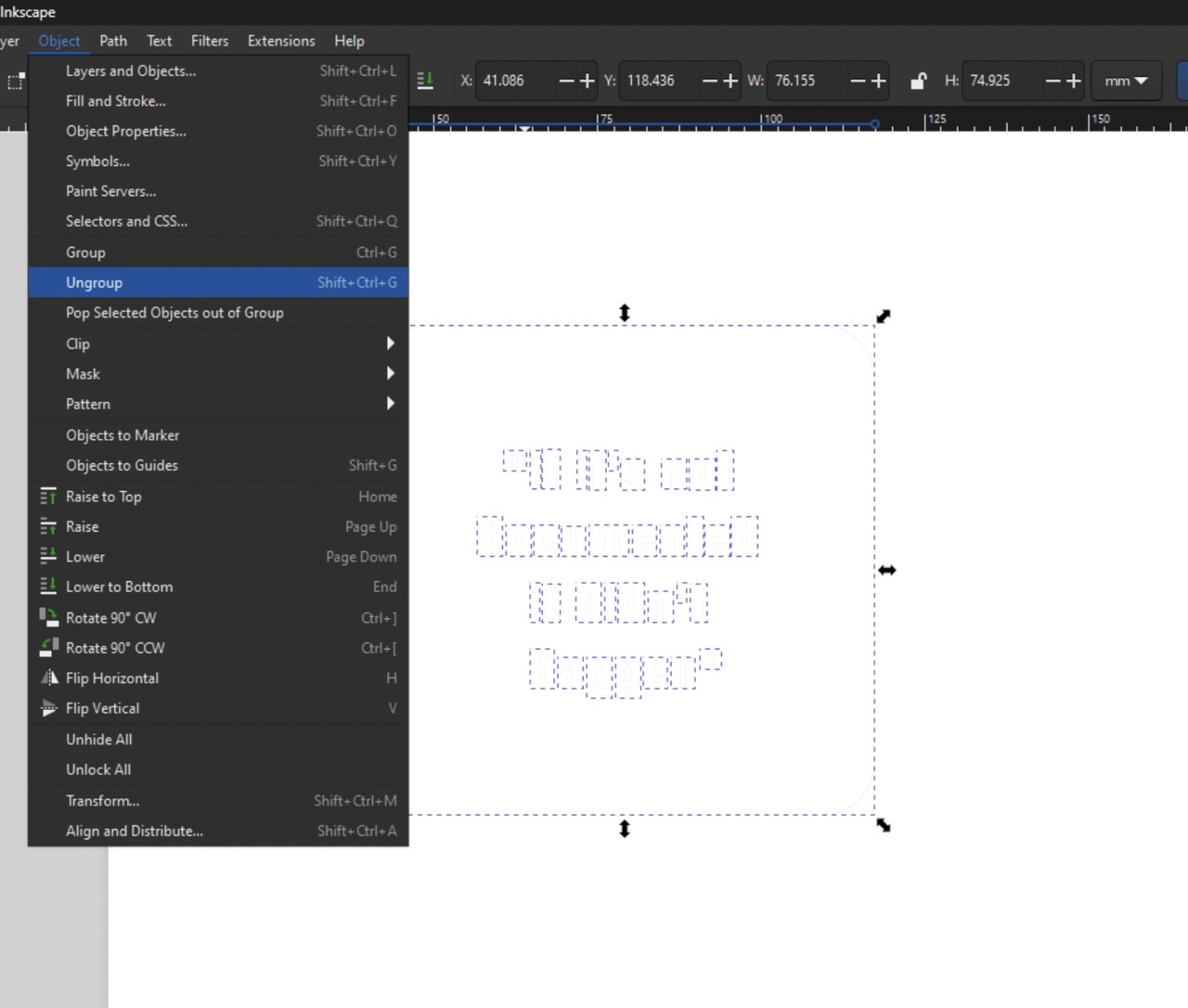
Ungroup the parts that were imported.
Select all and make sure the fill is set to none and the stroke is solid colour. We also need to make sure the stroke size is set to hairline.
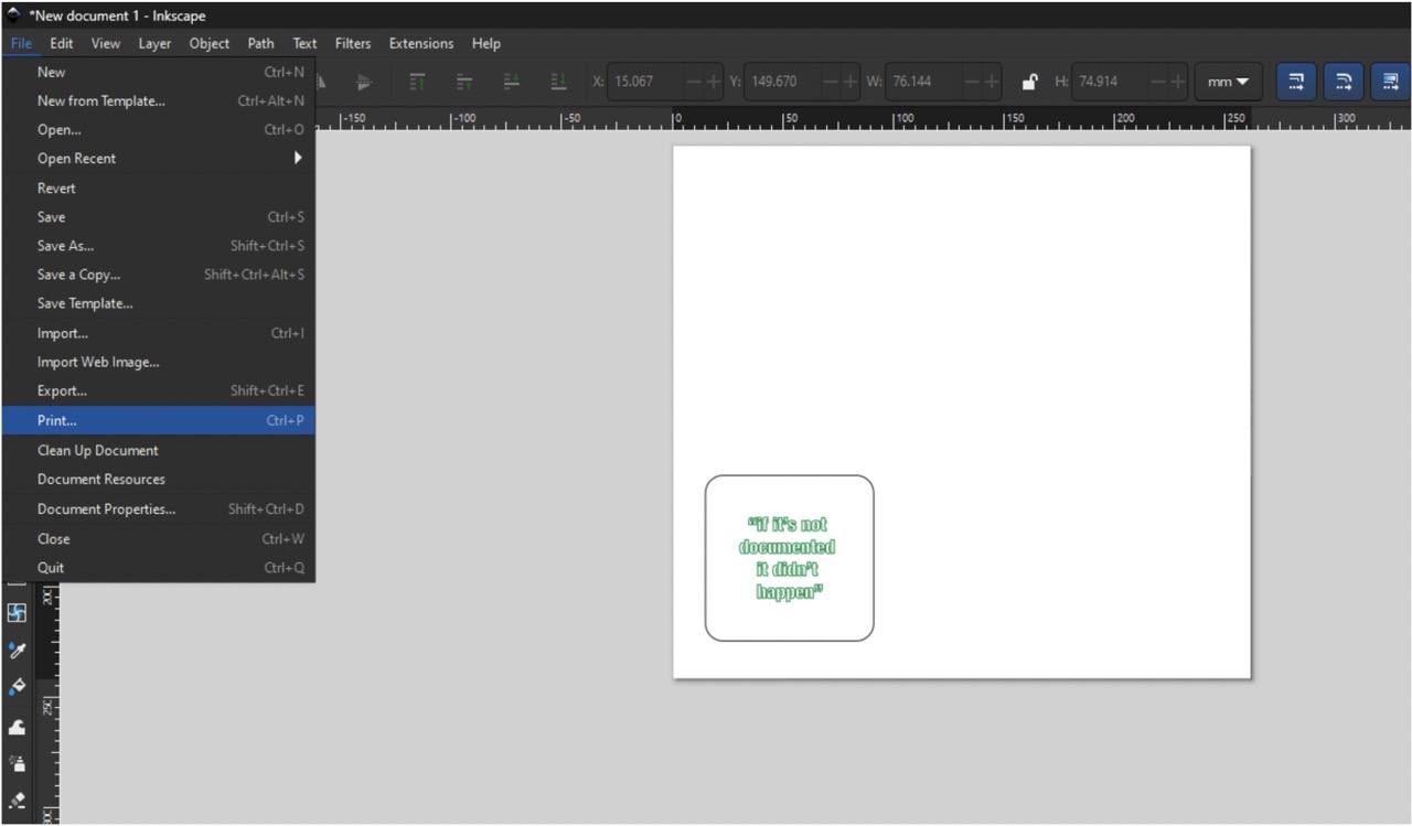
Place the parts on the artboard where you would like them printed in the vinyl. We can now >file> print
Print to the Roland GS2-24 Enter the part size again when instructed and press go.
The part should now cut.
I cut the text and the rounded square together
I also cut a rounded square on its own in white vinyl for the background.
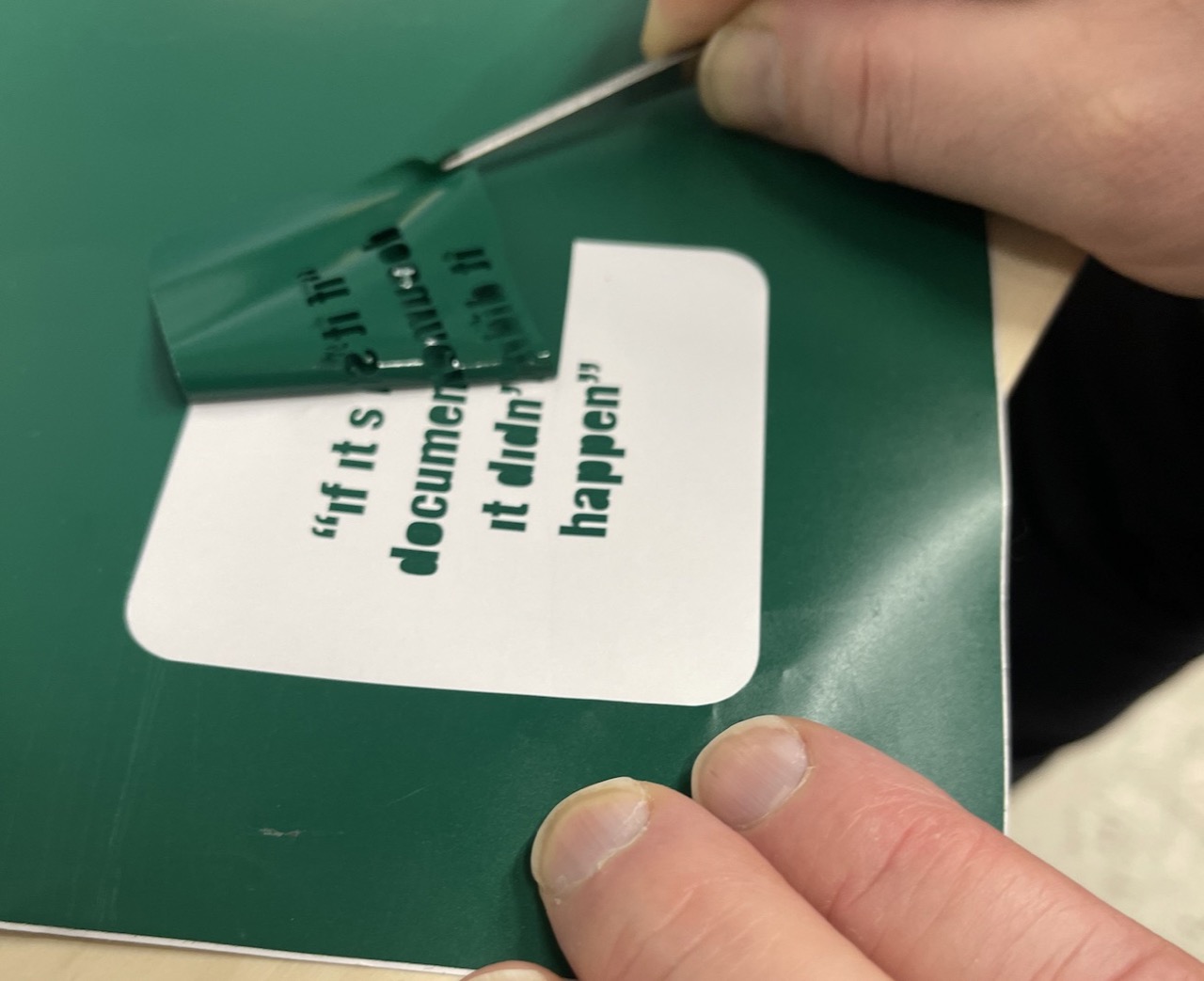
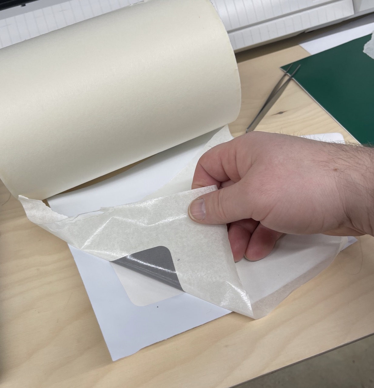
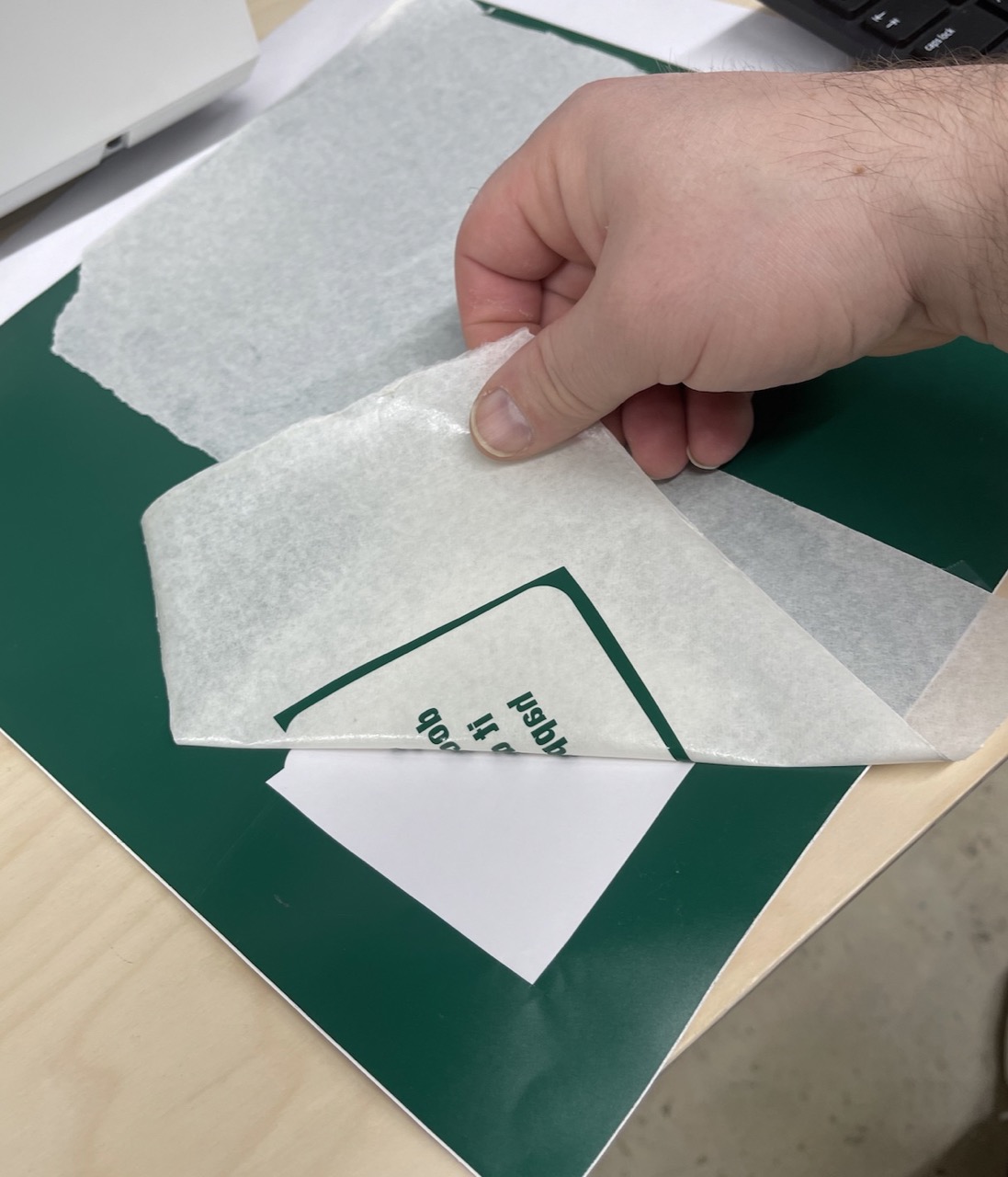
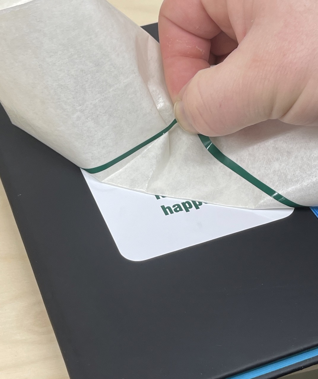
Time to weed out the text - this is a delicate process. We will need a scalpel/craft knife and tweezers. Do not pull directly up, shear the vinyl back at an angle. Some parts like the dots for the eyes might need to be placed back in place. Take your time!
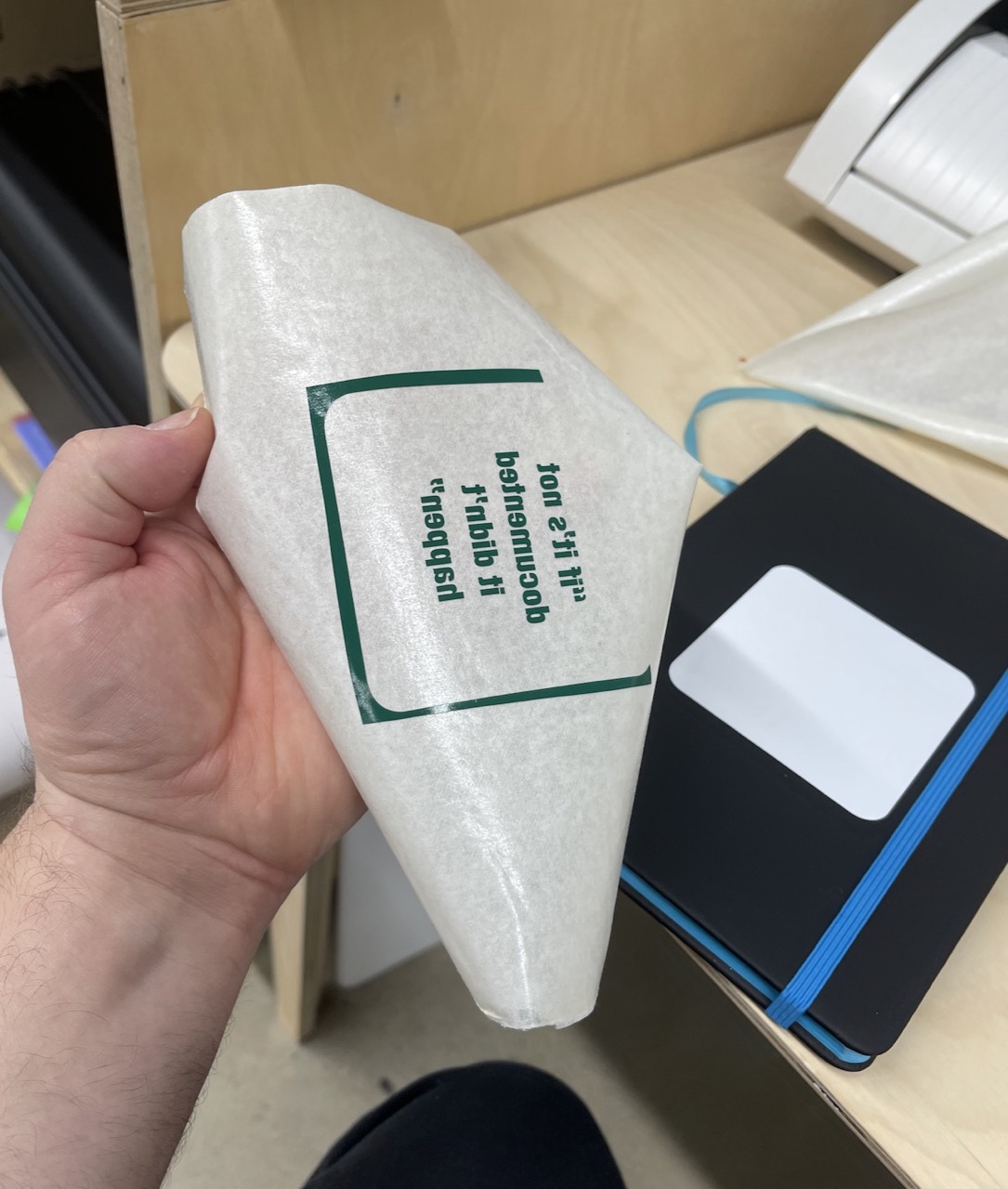
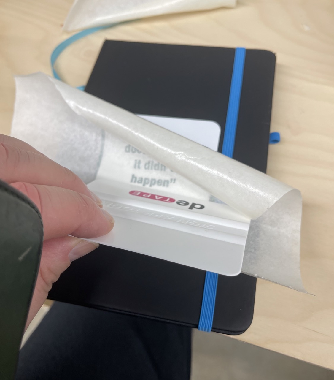
Use transfer tape on top of the vinyl to allow us to place it where needed. Use plenty of (reasonable) force when attaching using a spatula.
Prepare the surface to accept the vinyl – I cleaned the notebook surface using isopropanol and allowed it to dry.
I then applied the white background. Apply from one direction using the spatula to press down avoiding any bubbles – again use force
Next I aligned the text – notice how I used the rounded rectangle as alignment aids on the transfer tape. I only applied force with the spatula over the text
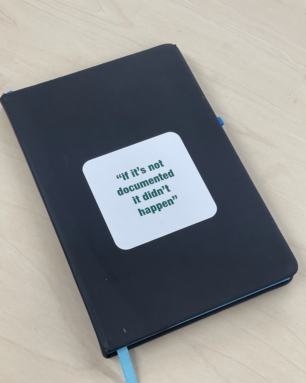
And there we have it … the Fab Academy mantra for the rest of Fab Academy!!
Parametric construction kit and Laser Cutting
I decided to try Rhino and Grasshopper to create a parametric model for this Week 3 Assignment.
I want to make something very simple that could be easily modified to create a range of geometric shapes to use as a connectable set of shapes.
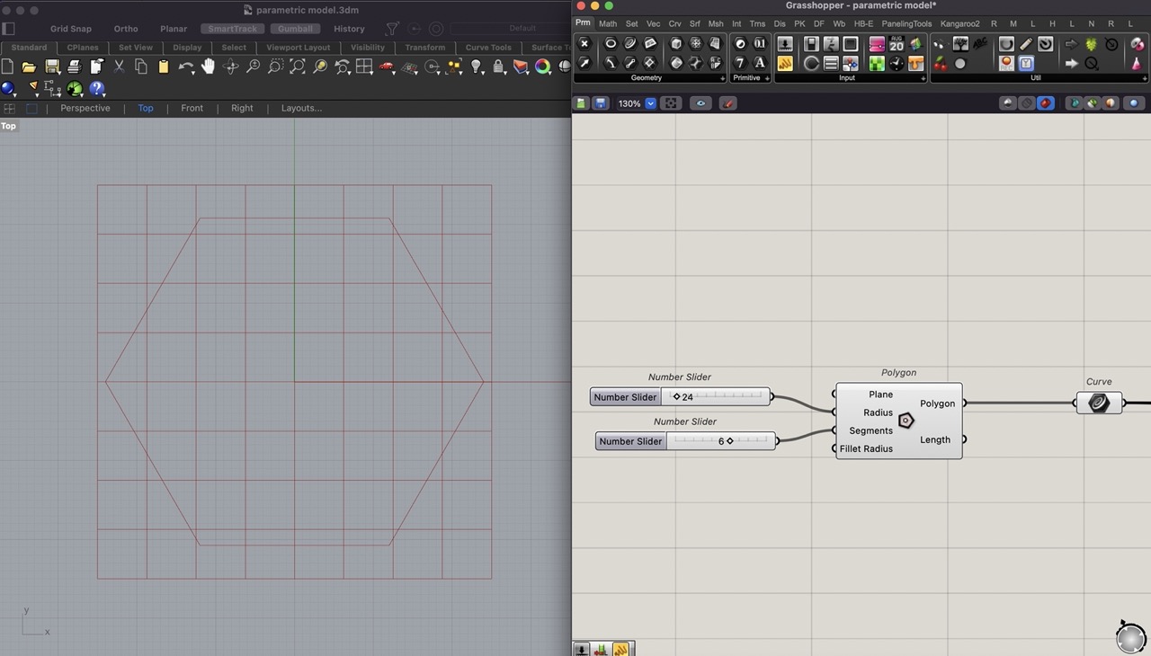
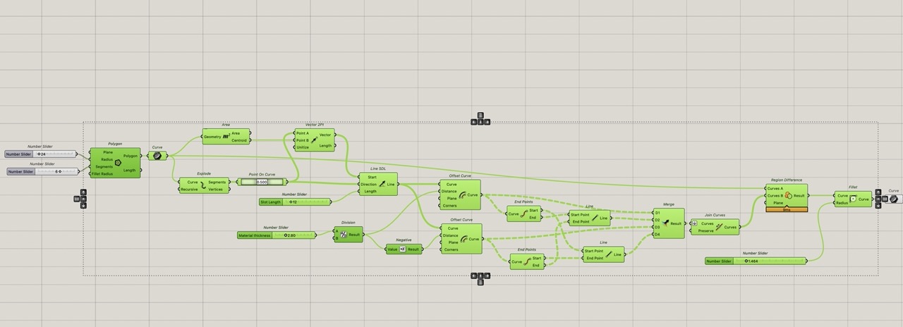
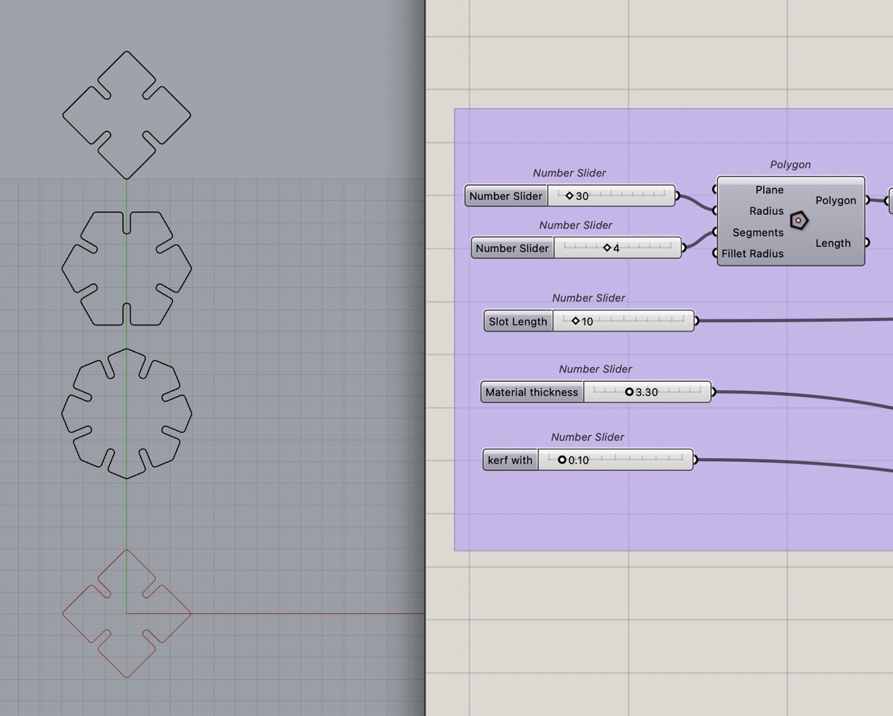
For this we used the polygon component in Grasshopper.
Number sliders are used to set the radius of the polygon in the component; this controls the overall size.
To create a slider in Grasshopper double click canvas type 5 < 24 < 100; this creates a slider going from 5 - 100 and set at 24.
With this we know the basic shape of our part; we can adjust the number of sides on the polygon and the overall size with the sliders.
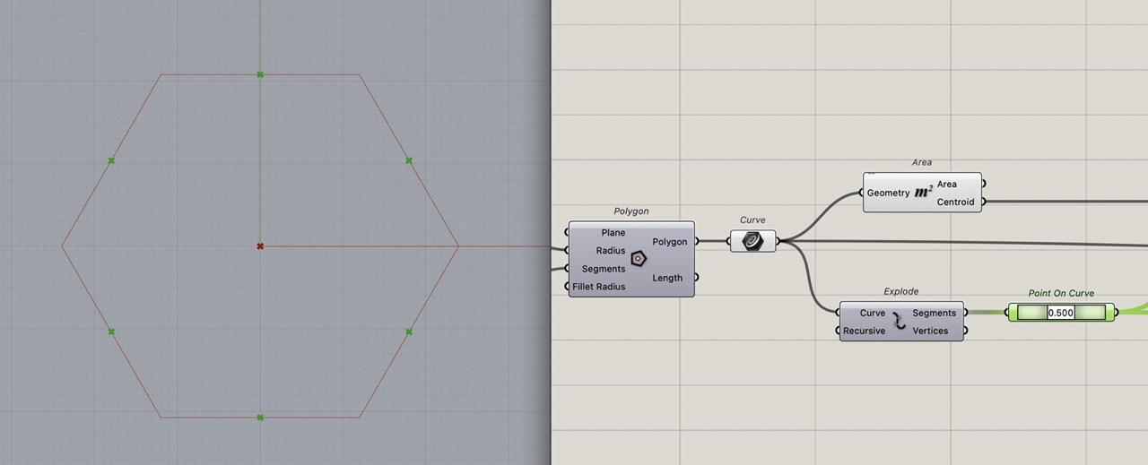
The outputs of the polygon component are polygon (represented as one single curve) and length.
To highlight this, I have added a curve component and connected the polygon output from the polygon component to it.
We need to add slots to do this; we have to identify the midpoint of each curve that makes up the polygon. To break the curve into individual segments, use "explode". We can then analyse these curves to extract the midpoint and if we want to adjust this later, we can use "point on curve".
Use "Area" component to find the central point on the polygon. This will be used to create the slot line from the midpoint to the centre point.
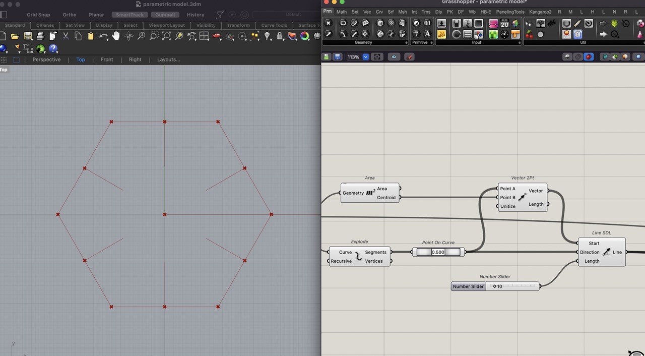
Use "Vector 2PT" and "Line SDL" to connect the midpoint and centre point to vector 2 point.
Connect the "Point on Curve" to the start point of "Line SDL". Add the vector to the direction. A number slider to specify the length of this line.
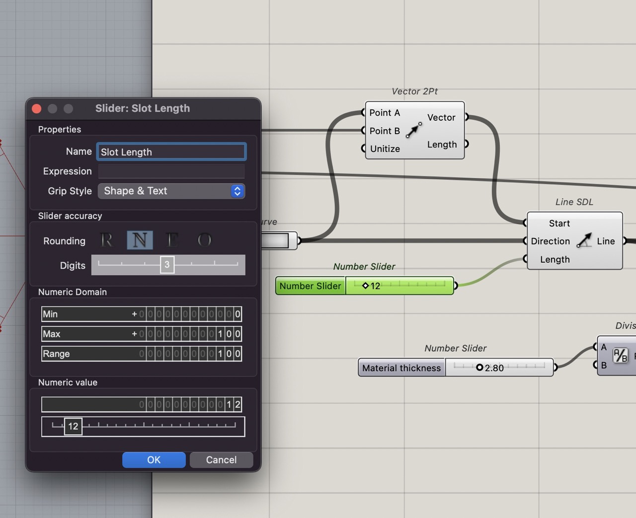
Double click the slider to change the name and, in this case, slot length. We can also adjust things like min, max of the numeric domain and the set point. And set the slider accuracy and decimals or whole numbers.
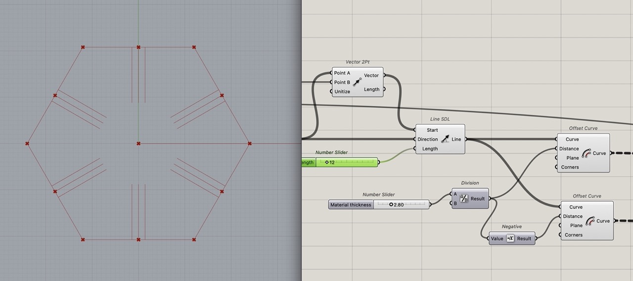
Offset this line each direction to create the slot; this will be half the material thickness in each direction.
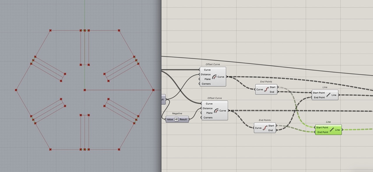
Close the curve to a rectangle using the "end points" and the "line" component.
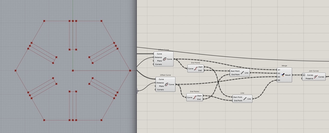
These 4 lines - the 2x "offset curve" and 2x "line" components - can be merged to create one closed curve using the "join" component.
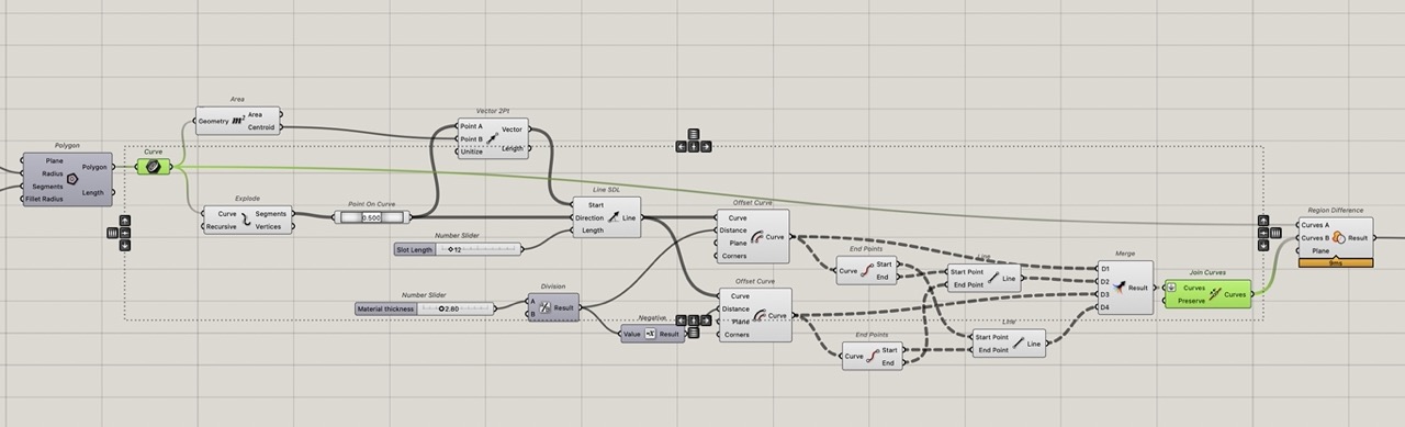
These closed rectangles need to be removed from the original shape. Use "Region Difference" component to do this. Connect the polygon curve we created at the start of the definition and the "joined curve" component just created.
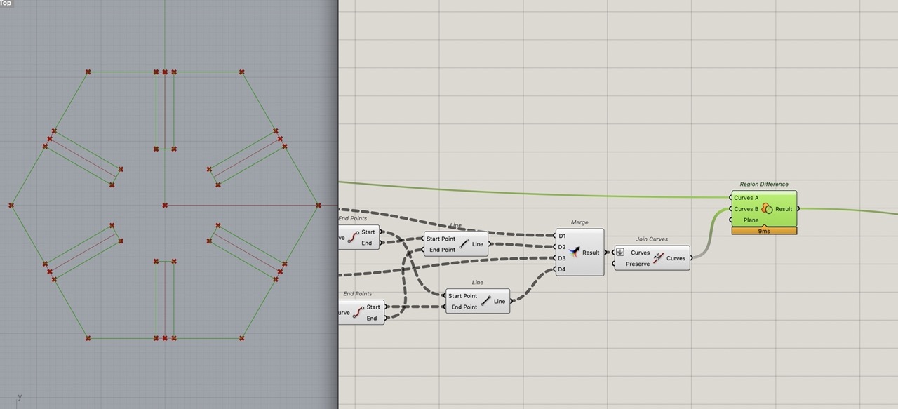
This should create one flat curve. You will need to flatten the curves coming into join curve; you can zoom in, right click on the node and select flatten.
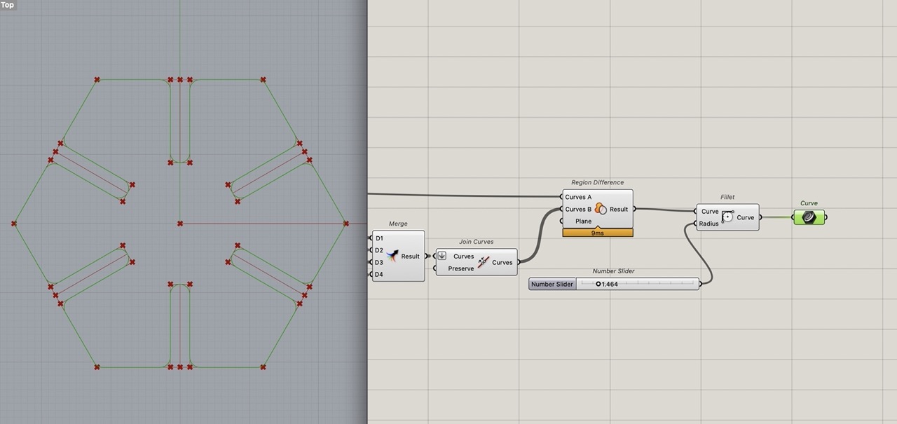
Add the curve component to tidy up the definition. Then we can bake this. But first we need to add Kerf allowance.
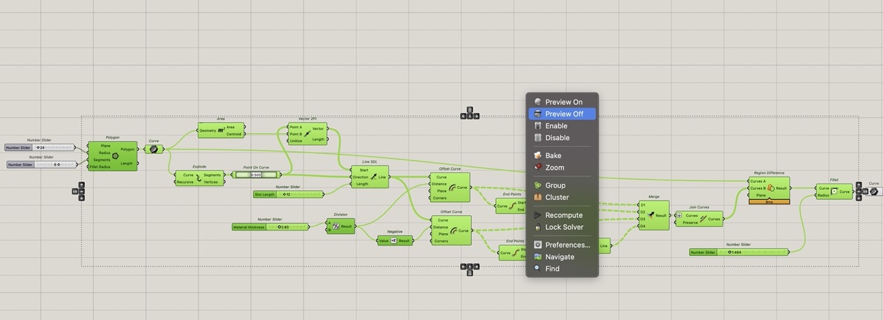
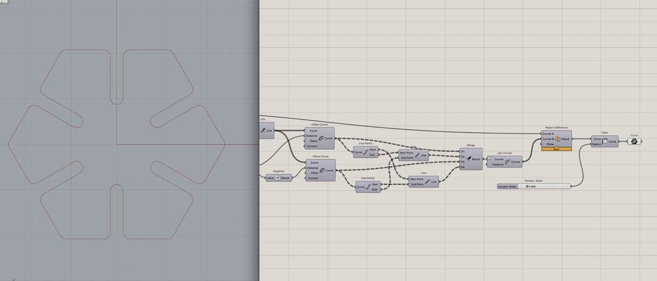
We can select all components except the last curve component, right click on the canvas and click "preview off".
This gives us a clean uninterrupted view of the outline curve. Which should be one closed curve planar curve. (Add a "panel" component to see what is being output from the curve component or any component for that matter; just connect the node you want information from.)
We can add a kerf with slider and a subtraction component Add the material thickness slider to A on subtraction and the Kerf Width slider to B and then connect this to where material thickness was before that.
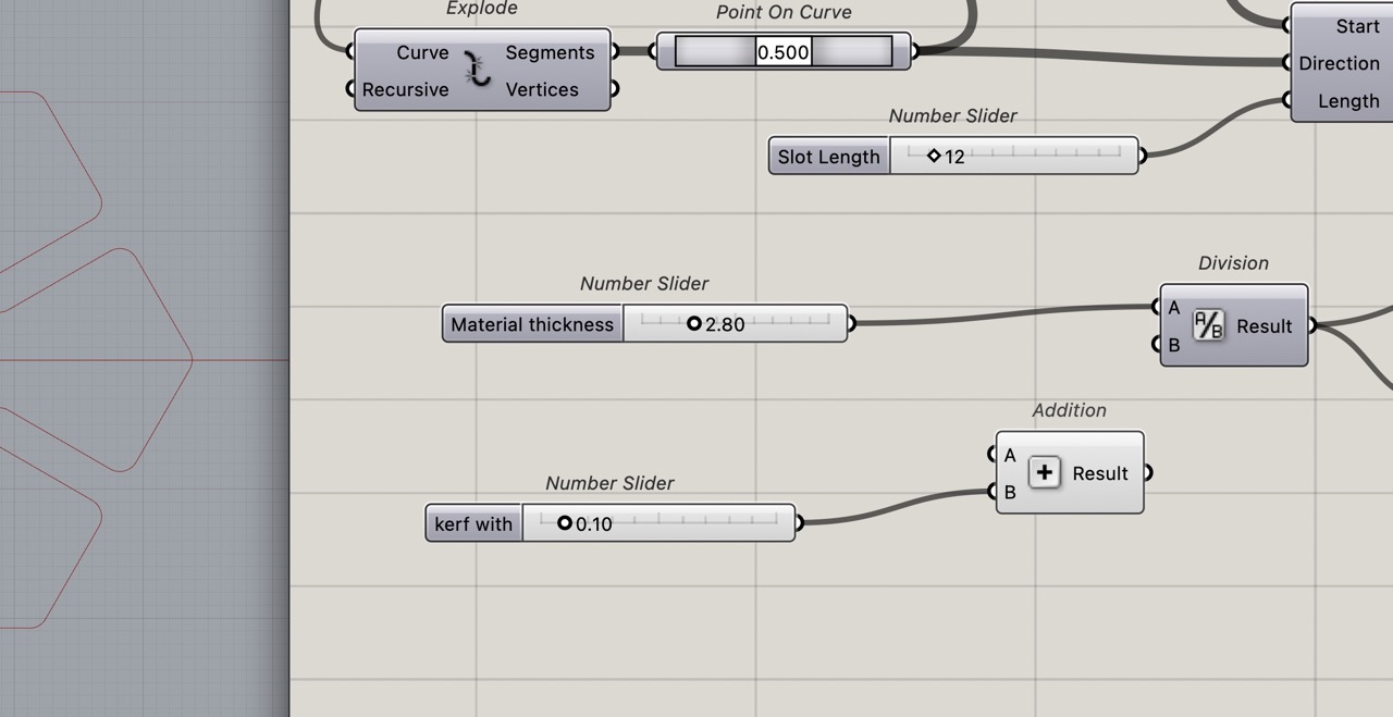
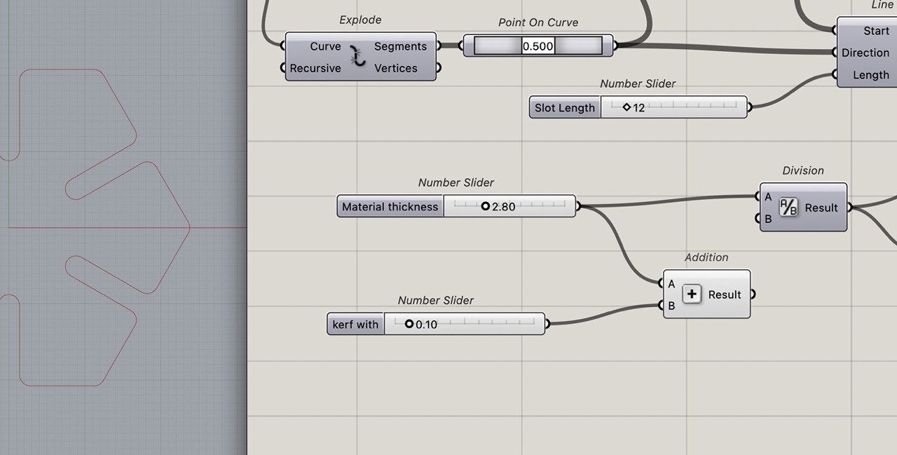
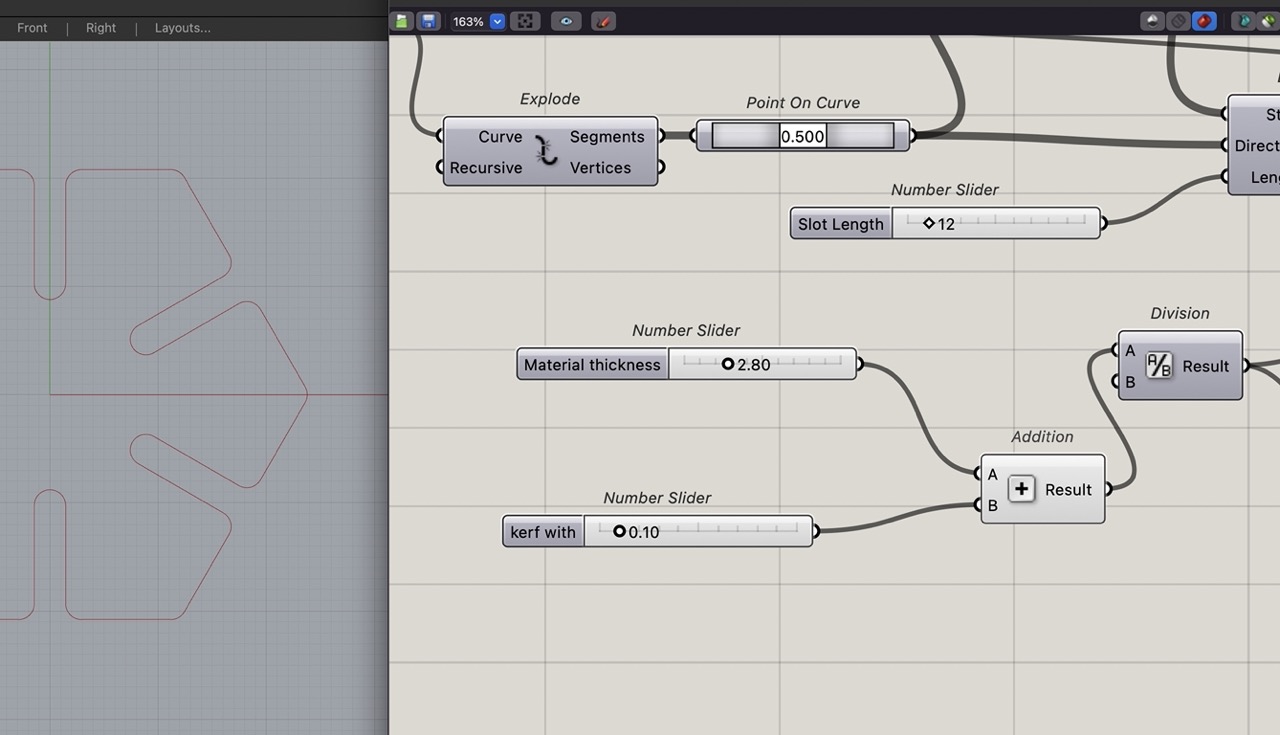
With this done we can now set your material thickness and kerf width sliders.
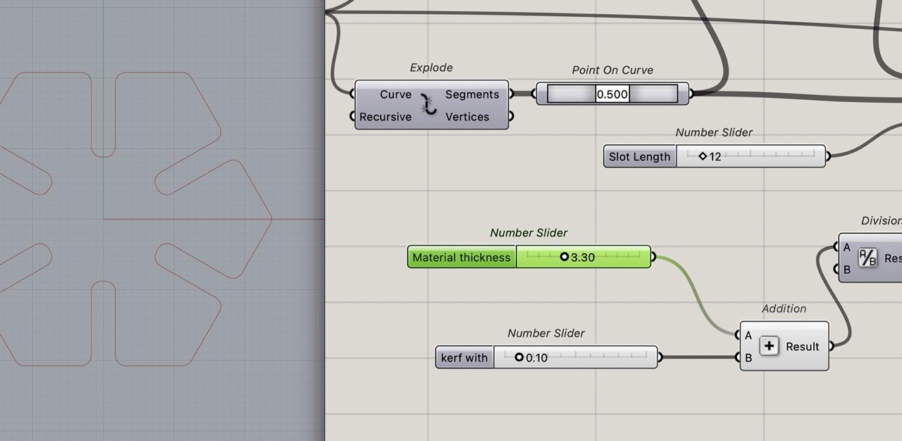
I rearranged the sliders and renamed them appropriately so they are to the left of the definition
We can now bake the curves at the end of the definition into Rhino - I like to bake them onto one layer, select the curves in the layer and export as DXF or SVG to laser cut.
I exported as DXF as the export seemed to work better for me.
Save to USB or SD card; in this case, I decided to cut them on the Laser Pro X500II. Bring the SD card or USB to the computer connected to the Laser Pro X500II
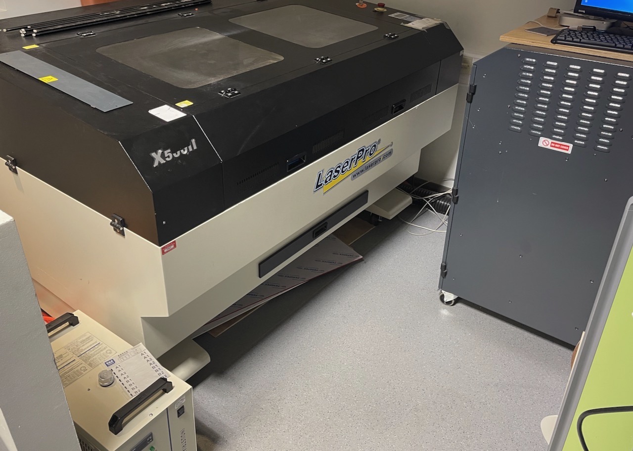
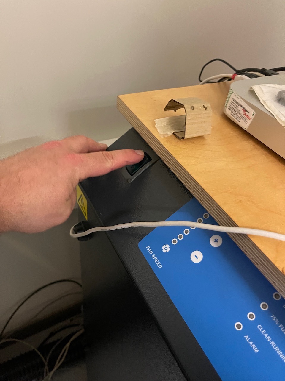
Power on the Laser Pro X500II using the isolator switch on the right side of the machine.
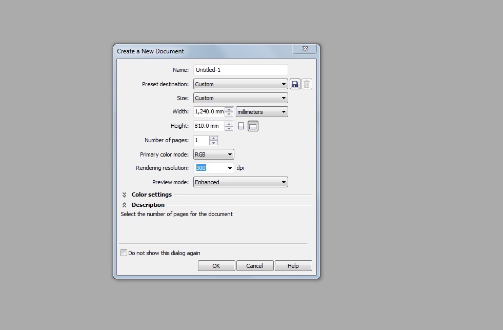
Open Corel Draw
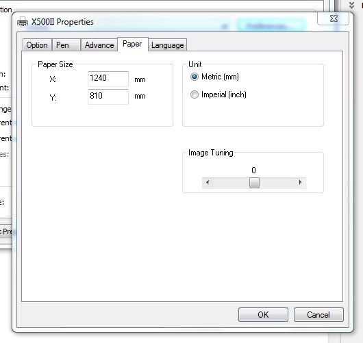
Create a new document RGB colour format and the size of the cut bed 1240mm x 810mm
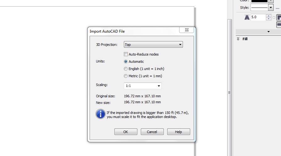
Import the DXF files - make sure scale is set 1:1 - when you press OK click enter on the keyboard to place the DXF on the Canvas
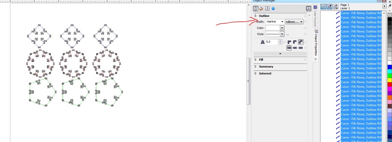
Make sure the line weight is hairline
Set colours if needed - these can set the cut order in the print dialogue - for now we can just set them all to black.

Arrange the parts on the canvas where you want to cut the parts from the stock.
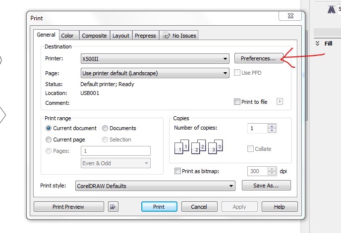
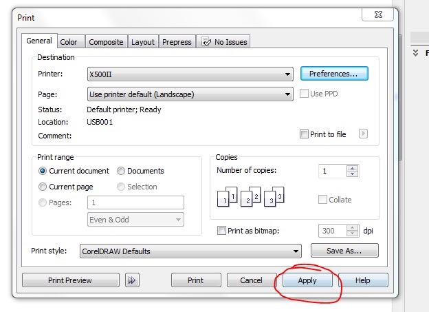
Go File>Print make sure it's the X500II printer that is selected and select preferences
Select manual colour fill in the first tab
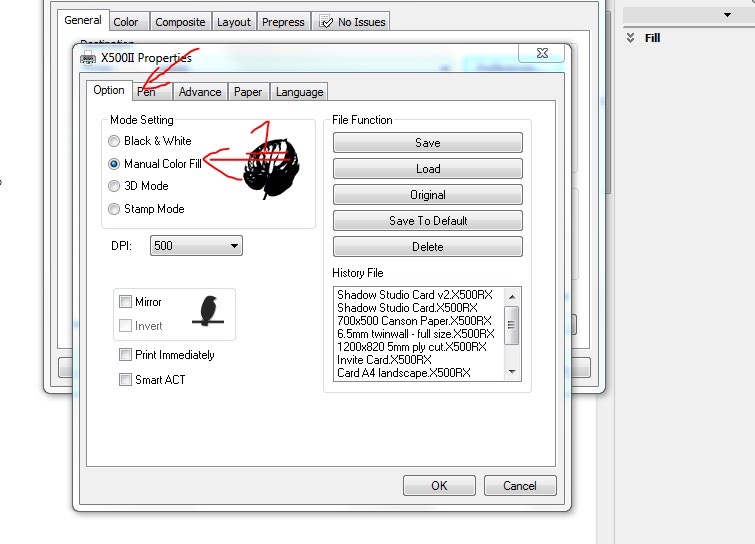
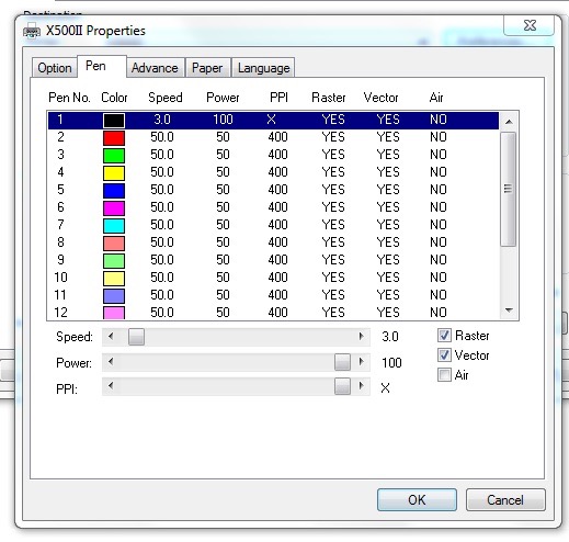
In the pen tab change the Speed, Power and PPI - These are the recommended settings to cut 3mm ply but can be adjusted and dialled in as needed.
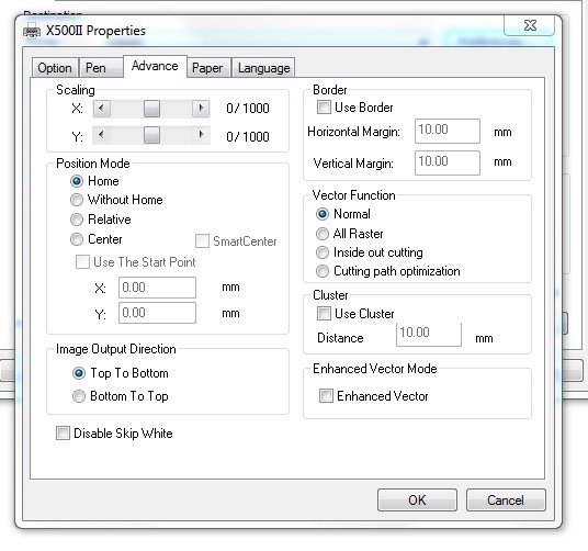
Advanced tab can be left as default.
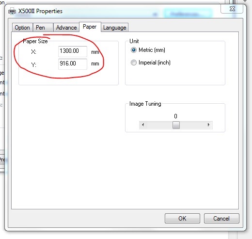
We need to change the paper size to match the canvas size we created in Corel Draw
Press OK - and click apply in the print dialogue screen
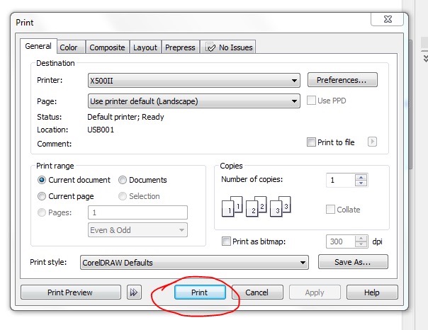
And press print - the file will be sent to the laser cutter.
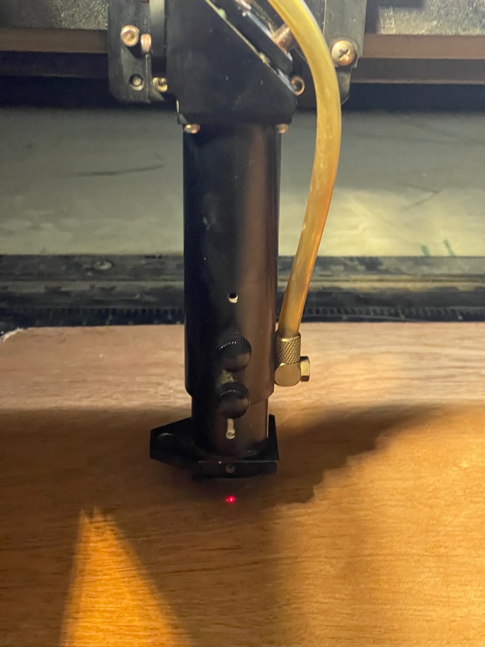
Place the stock in the top left corner of the bed and
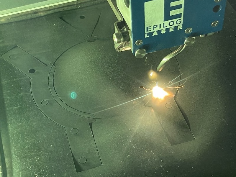
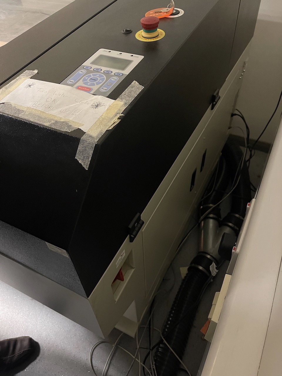
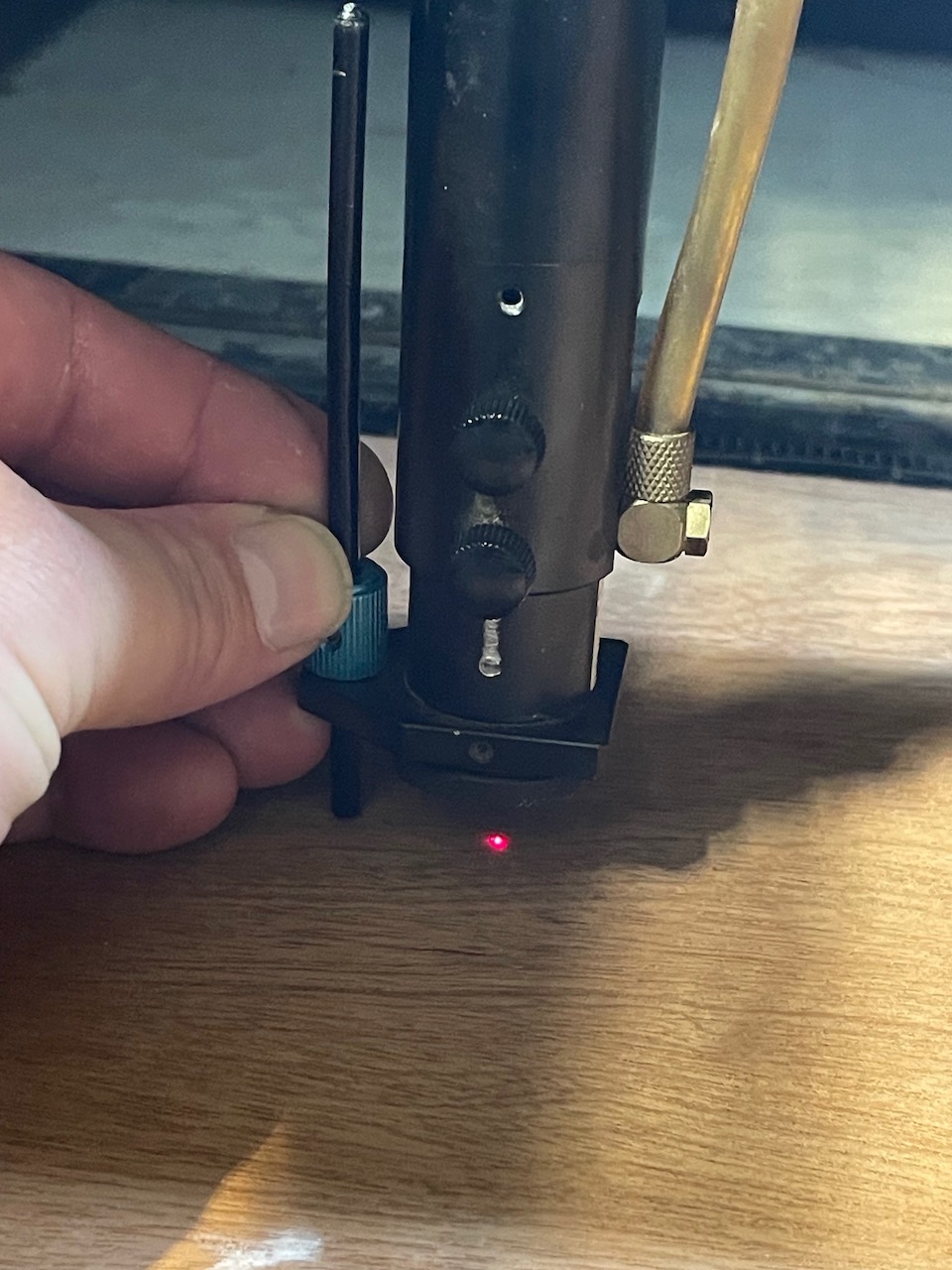
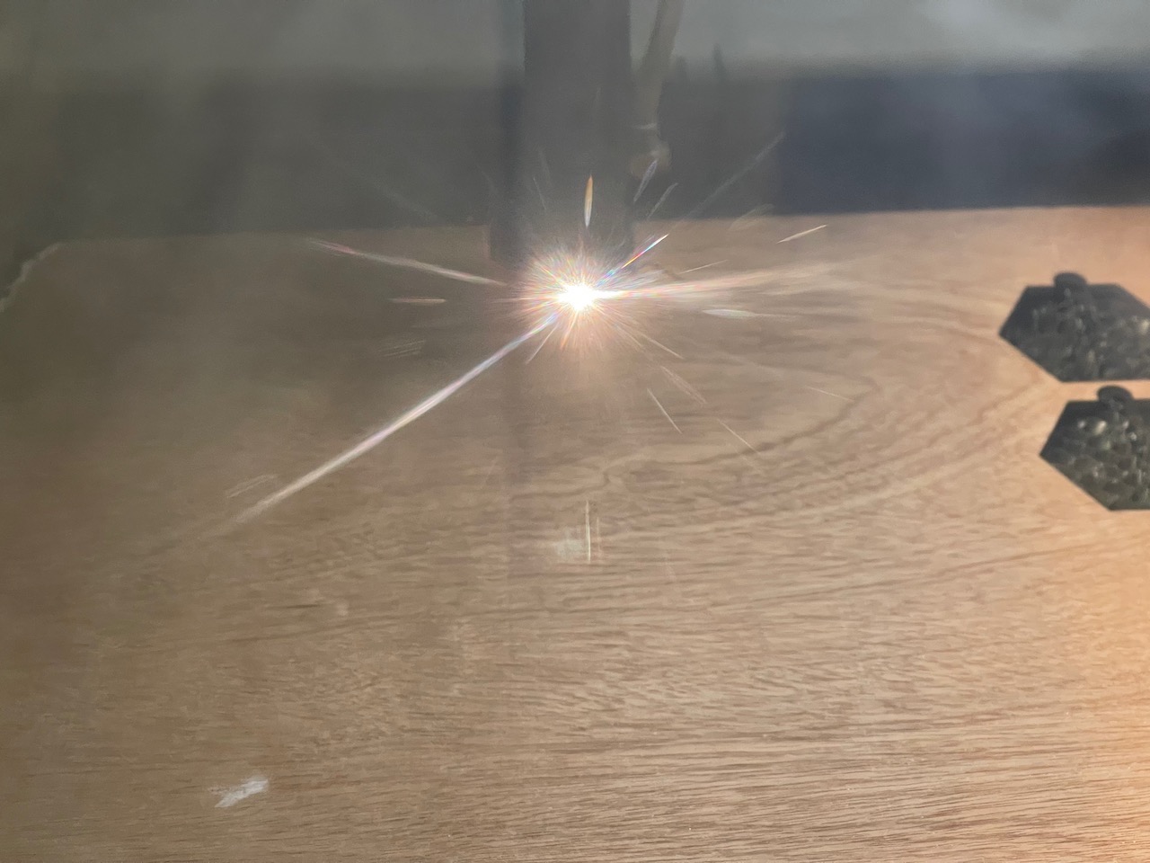
Move the laser nozzle into the middle of the stock. Focus the laser head using the focus stick by placing it in its holder on the left of the laser nozzle; hold it in place and loosen the two screws on the nozzle. The stick should just sit on the stock surface while being held in place - retighten the screws when the nozzle is focused correctly.
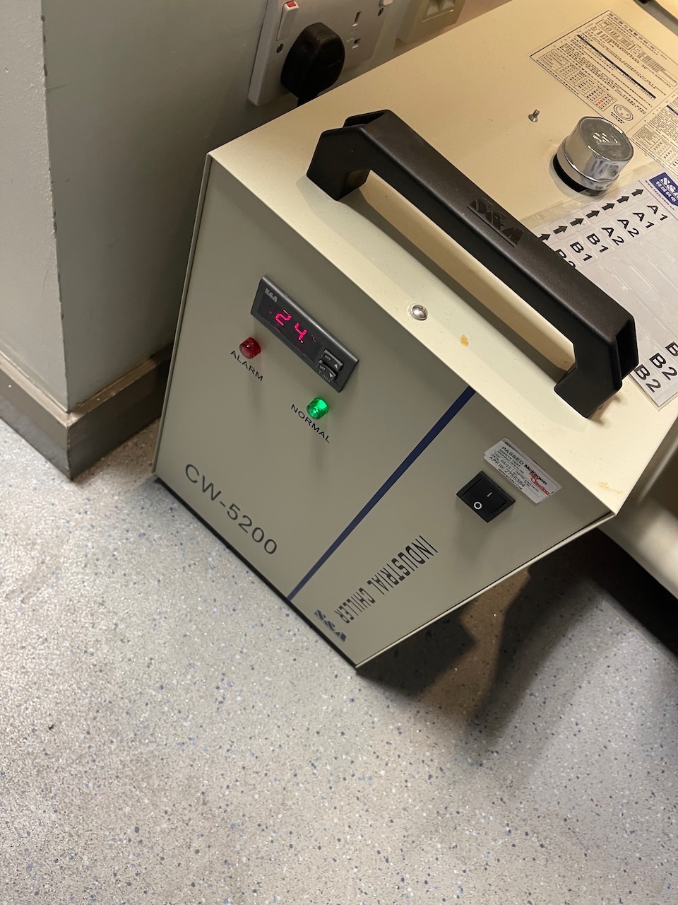
Once focused close the lid - make sure the water cooler is switched on, turn on the extraction,
Make sure the orange Door indicator light on the control panel is off (top left it's on in this photo) and press the middle of the start/stop button
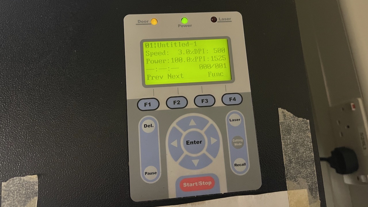
The part should now proceed and cut.
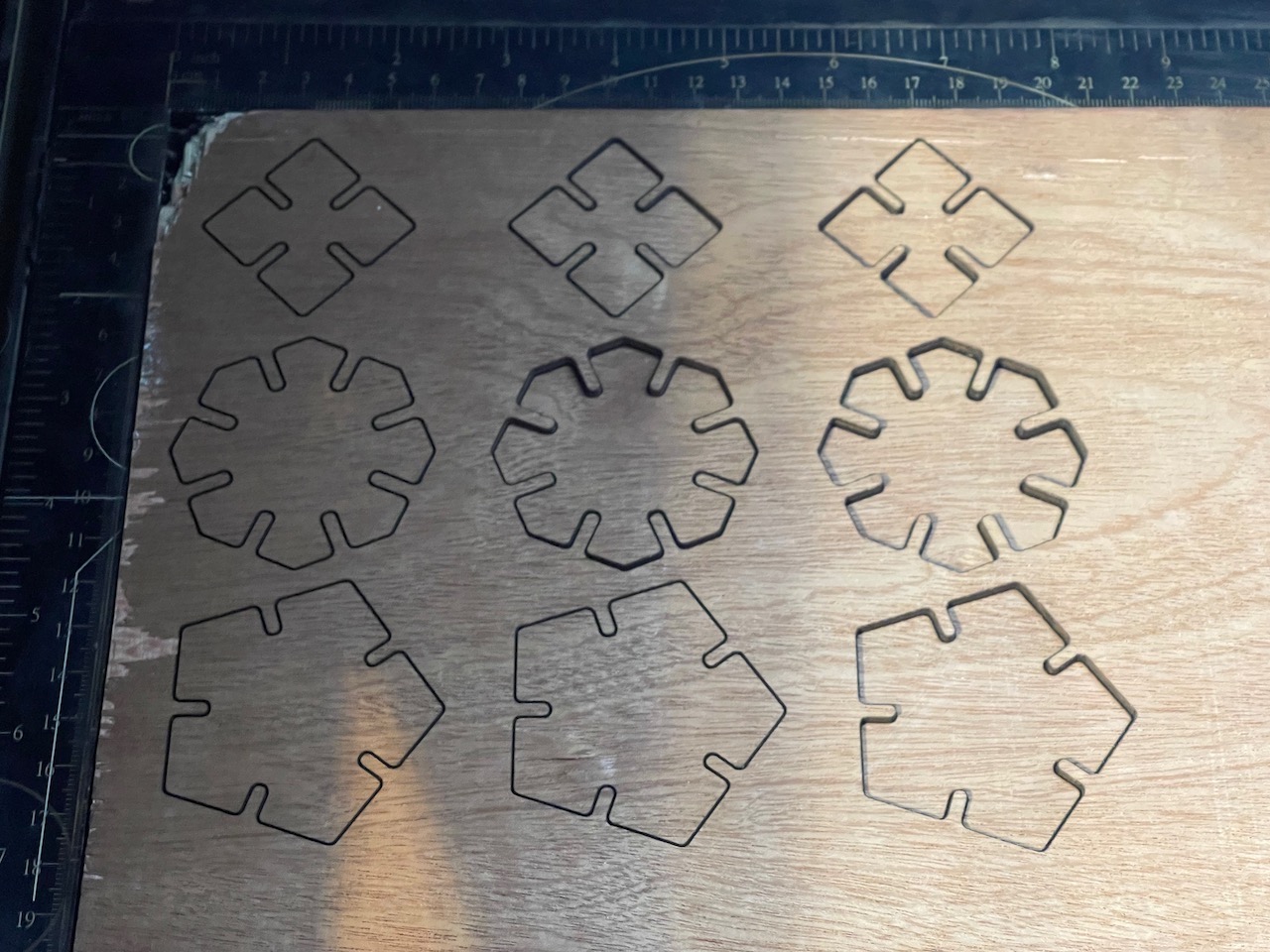
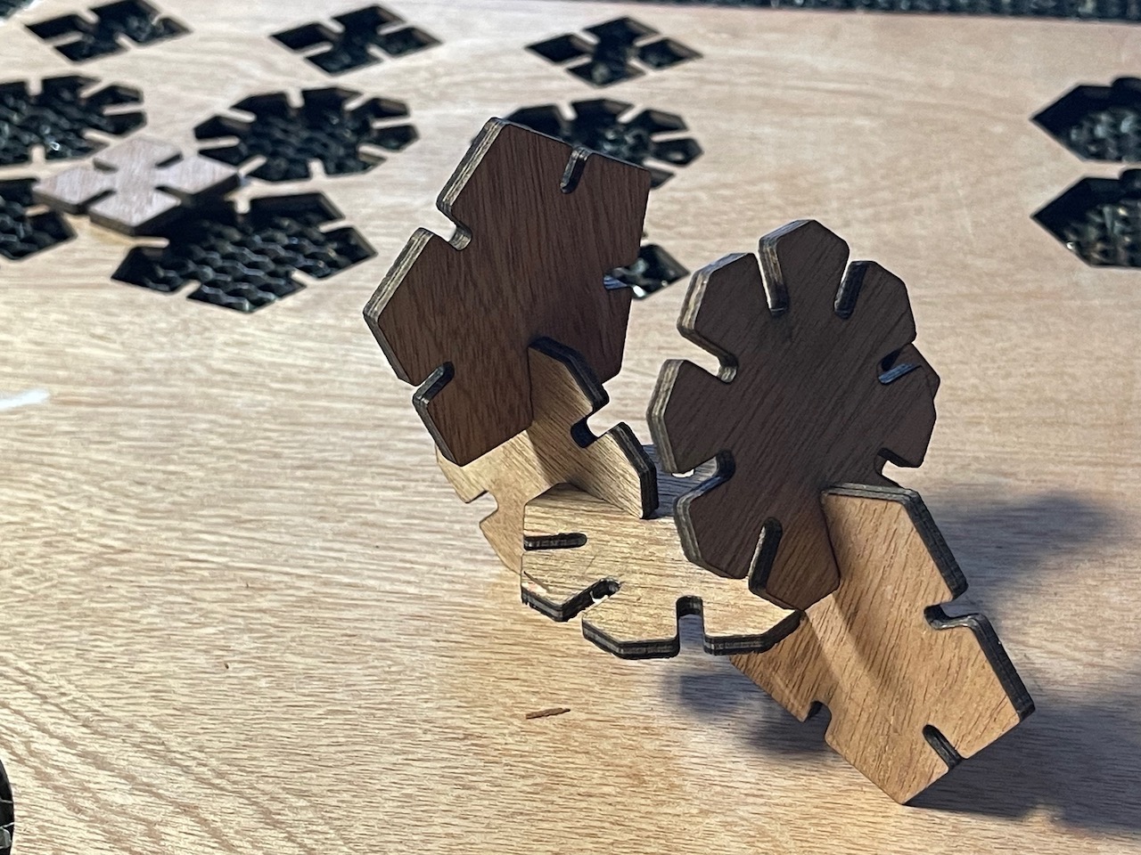
Some cut parts assembled
Learning Outcomes
Through this week's assignments, I gained practical experience in parametric design using Rhino and Grasshopper, learning how to create adjustable geometric shapes with proper kerf compensation. I developed hands-on skills in laser cutting, including material preparation, machine setup, and assembly techniques. Additionally, I mastered the vinyl cutting process from design to final application, including proper material handling, weeding, and transfer techniques.