Week 07. Computer Controlled Machining
We're going big with the CNC machines this week...
Group assignment: (link)
Do your lab's safety training
Test runout, alignment, fixturing, speeds, feeds, materials,
and toolpaths for your machine
Individual assignment
Make (design+mill+assemble) something big (~metre-scale)Extra credit: don't use fasteners or glue
Extra credit: include curved surfaces
Designing the test part
I designed a test part in Autodesk Fusion 360 to test the Biesse Rover CNC machine. I used the 10mm cutter to cut the part.
I started using the text feature in sketch in Fusion, see below
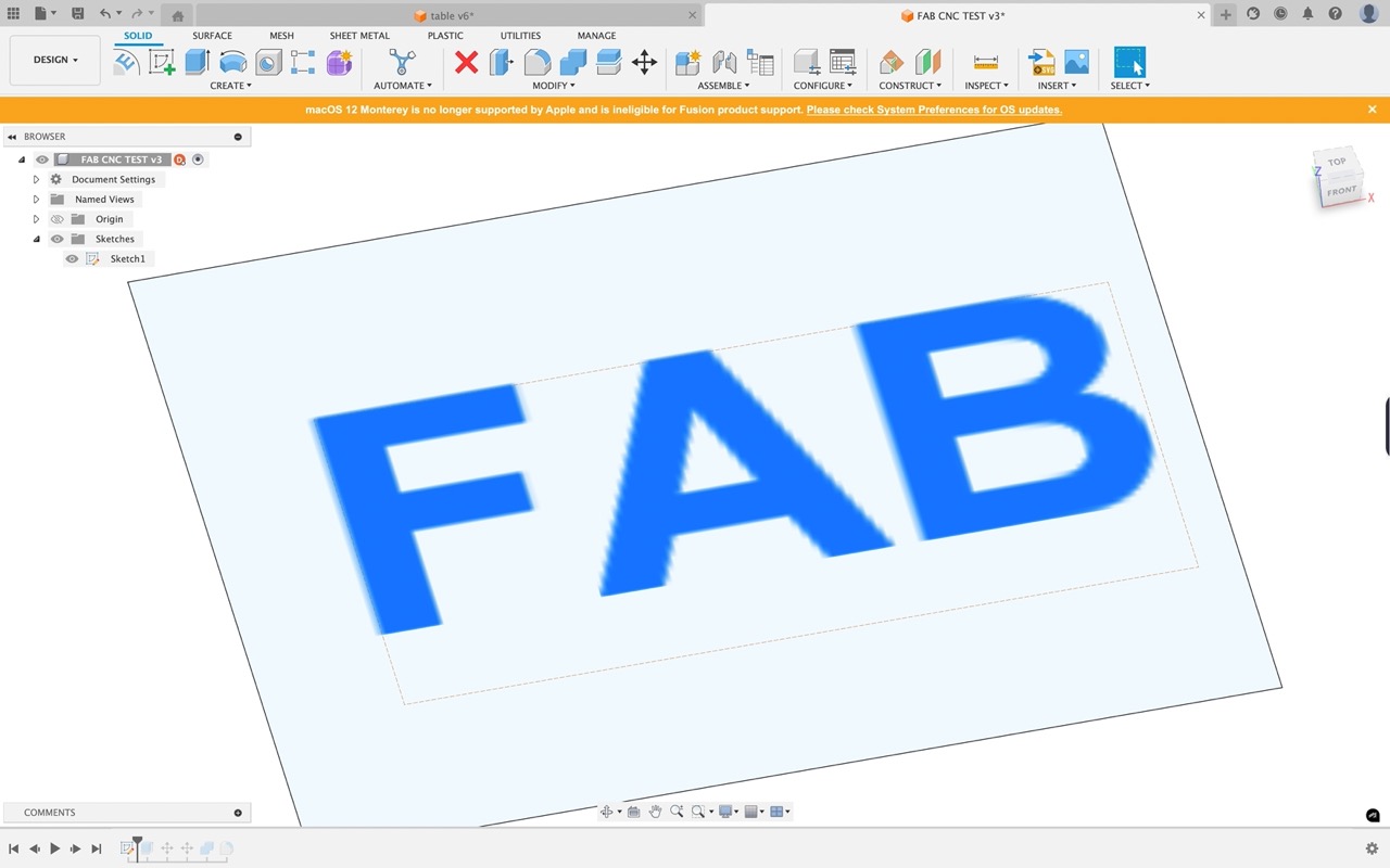
I extrude the text
I then move the letter bodies to intersect so they will form one part

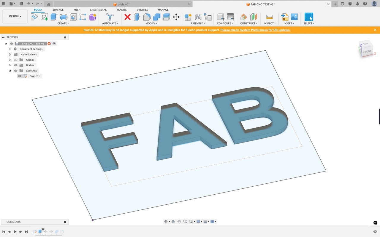
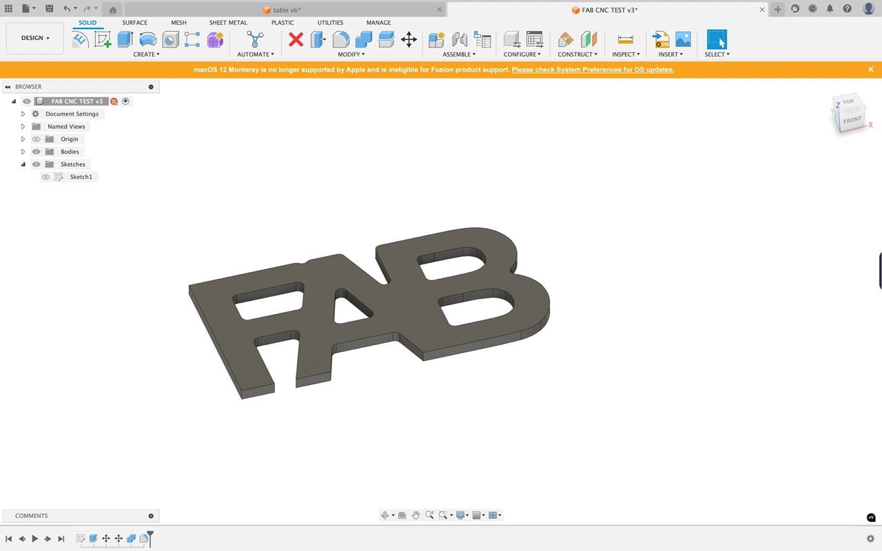
Once overlapping, I use the combine tool to form one part

I add some fillets on the inner corners so the cutting tool can get in to cut them.
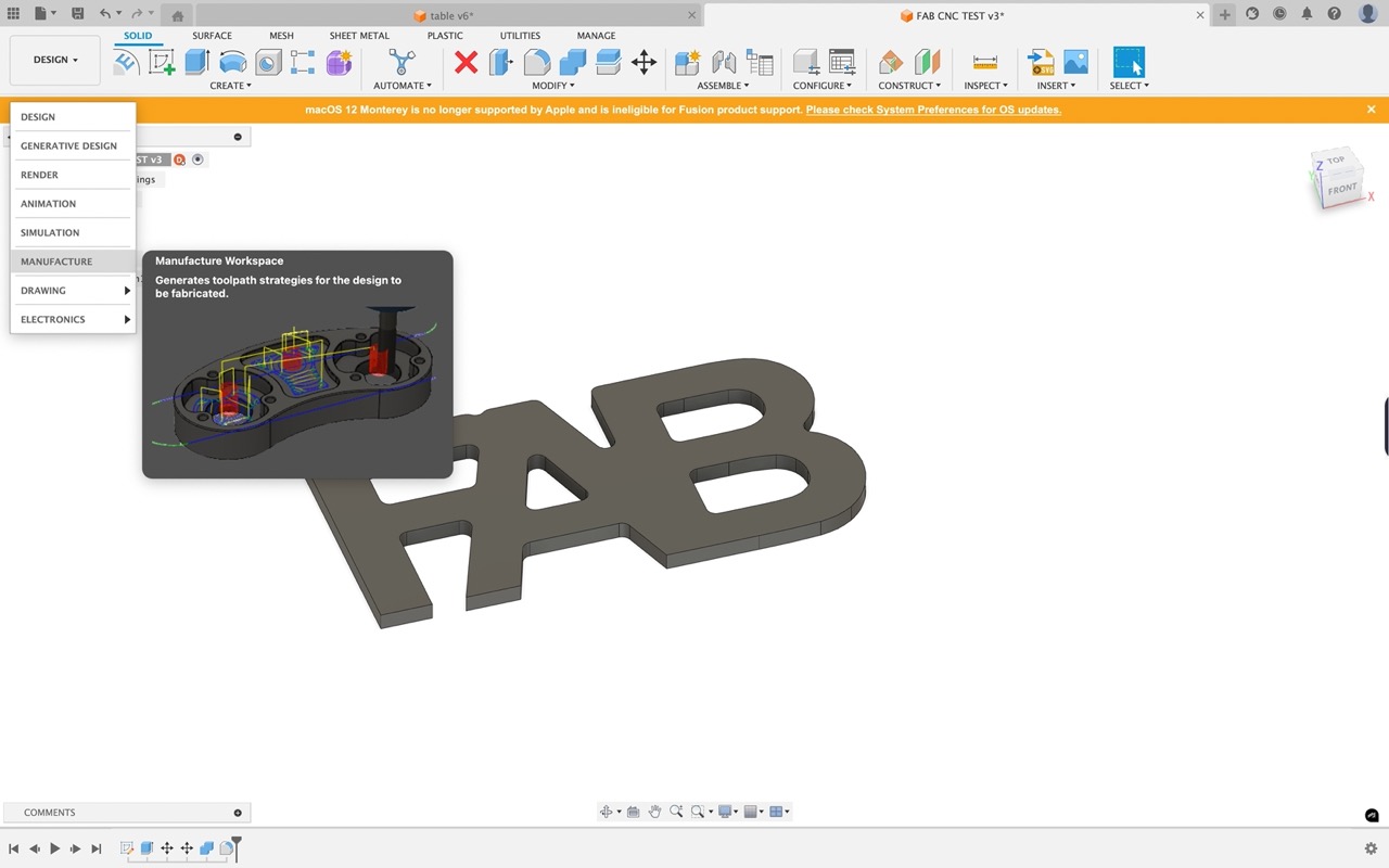
We are now ready to create our toolpaths, change workspace to manufacturing in the top left corner.
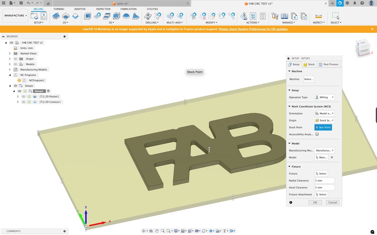
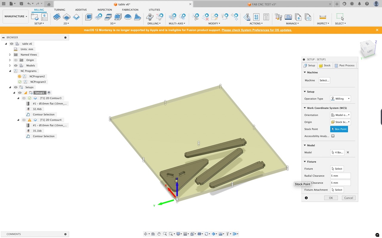
Create a new setup, a new dialogue window opens, in the first tab work through the options.
We don't actually need to select a machine.
Select milling as operation type.
In Work coordinate system set up as shown
Under model select the body
And in fixture we can leave that for now - if you have a fixture setup on your CNC such as a clamp etc. you can enter it here - you will need a model of it in your design.
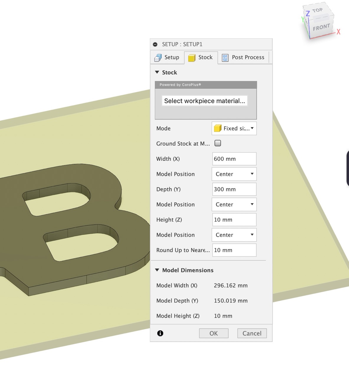
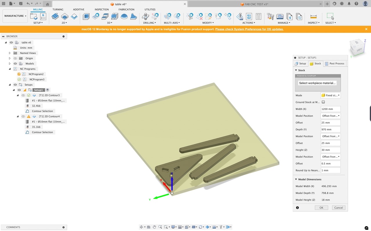
Go into the next tab and set the stock size to fixed and enter the size of the material you are using. Click OK
We can now select a tool 2D Pocket from the 2D section in the menu bar.
Click on select tool. We will select a 10mm end mill - you can create one or select from the Fusion library - it is a good idea to set up your own library with tools that reflect what you have available in the CNC machine.
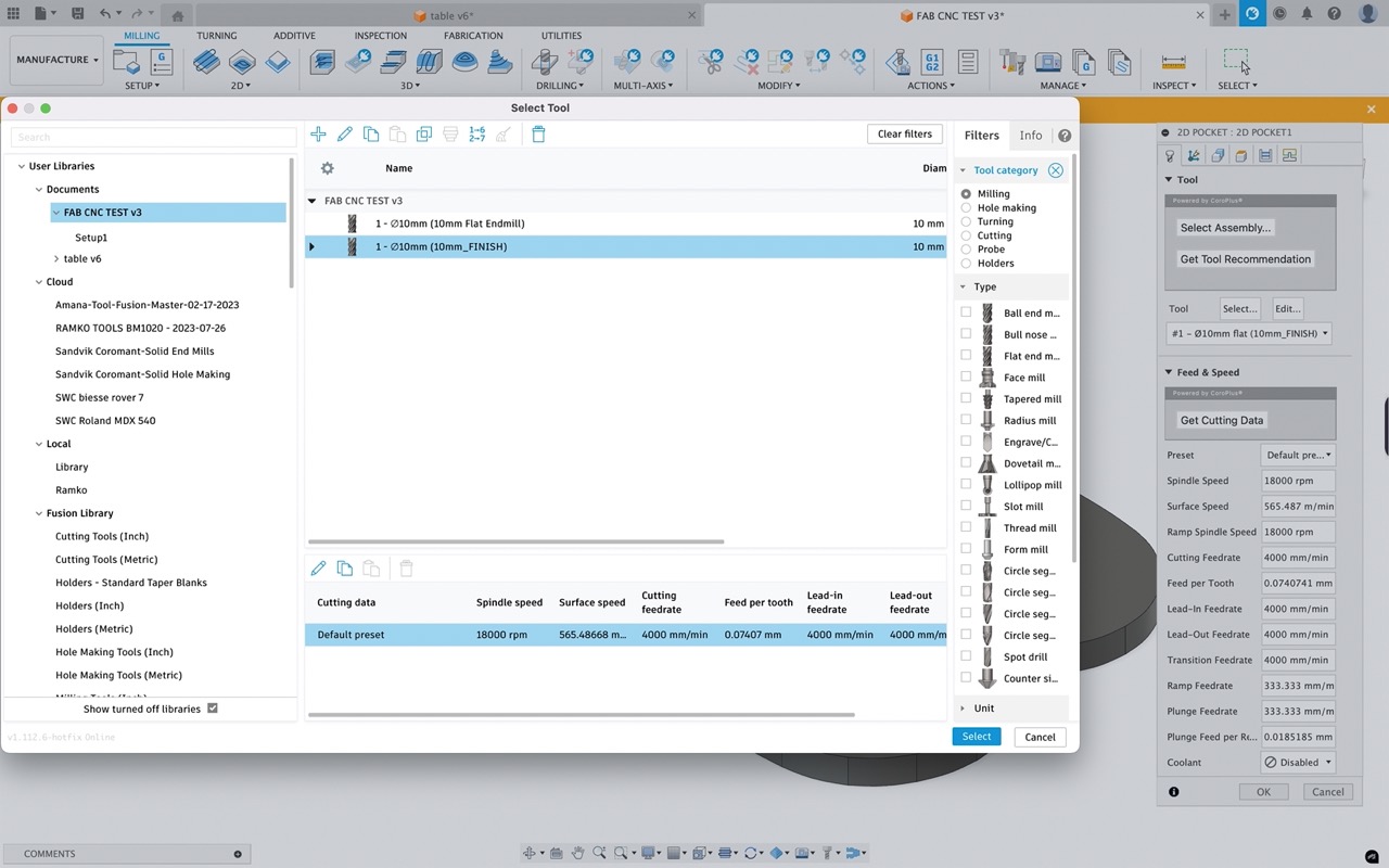
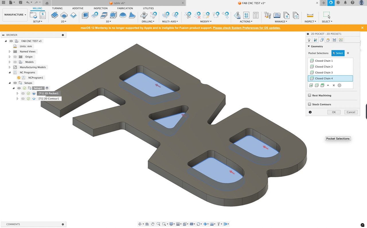
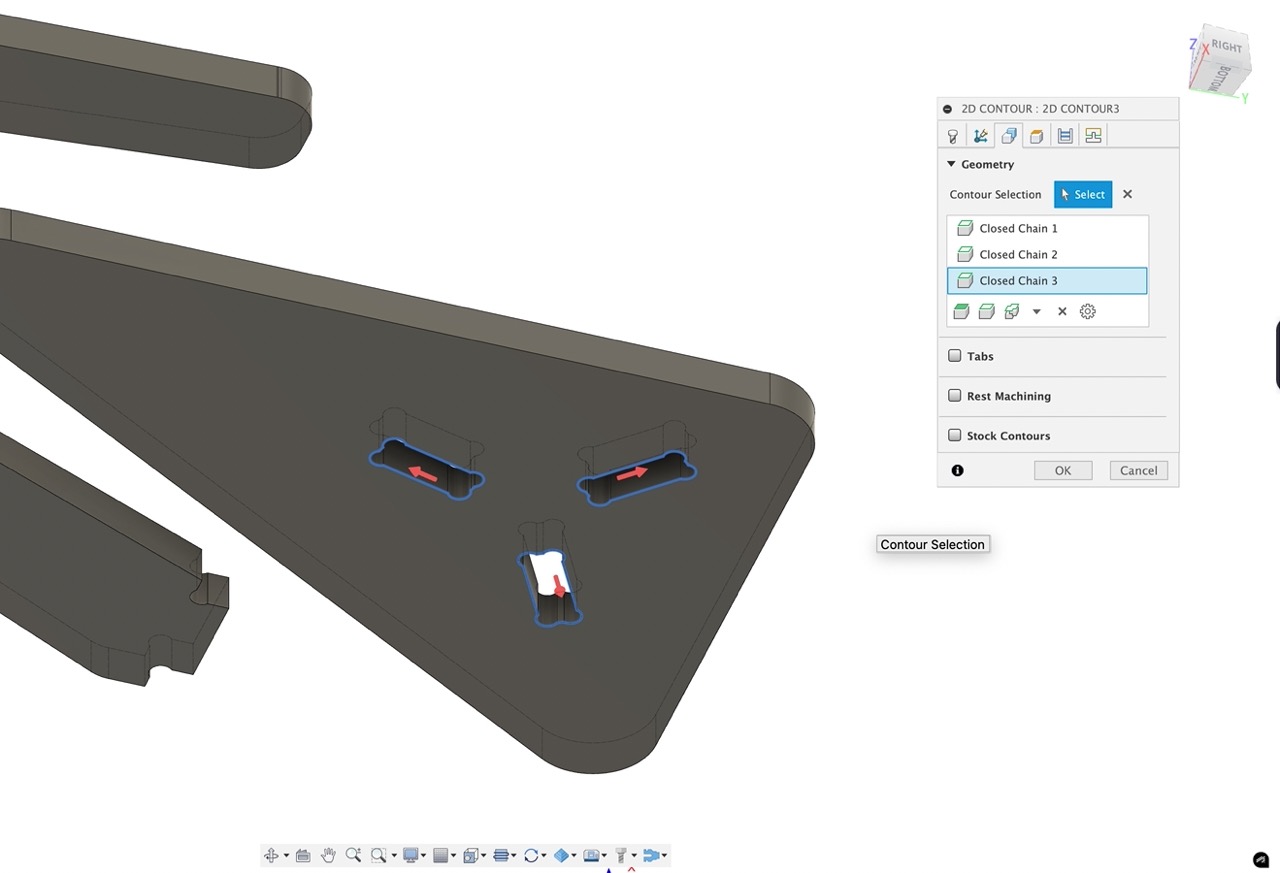
Once selected we can skip the next tab and move to the geometry tab.
We can now select the inner loops at the bottom of the letters as shown.
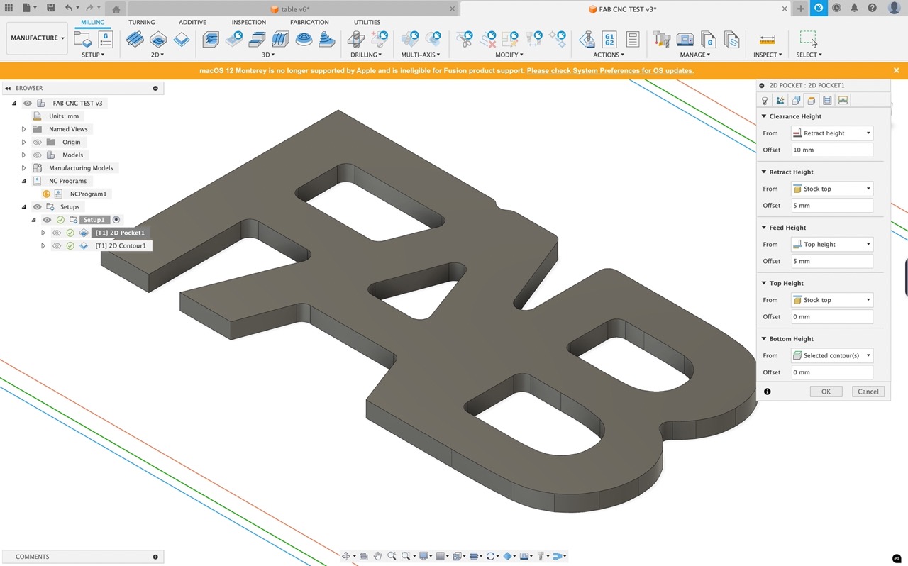
Move to the next tab and make sure you are happy with the heights. This is where you can set how deep the cutting tool will go so if you have a spoil board you can set your bottom height to drop down by 1mm or so - BE CAREFUL WITH THIS YOU DON'T WANT TO DAMAGE YOUR CNC MACHINE.
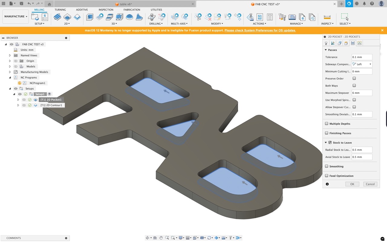
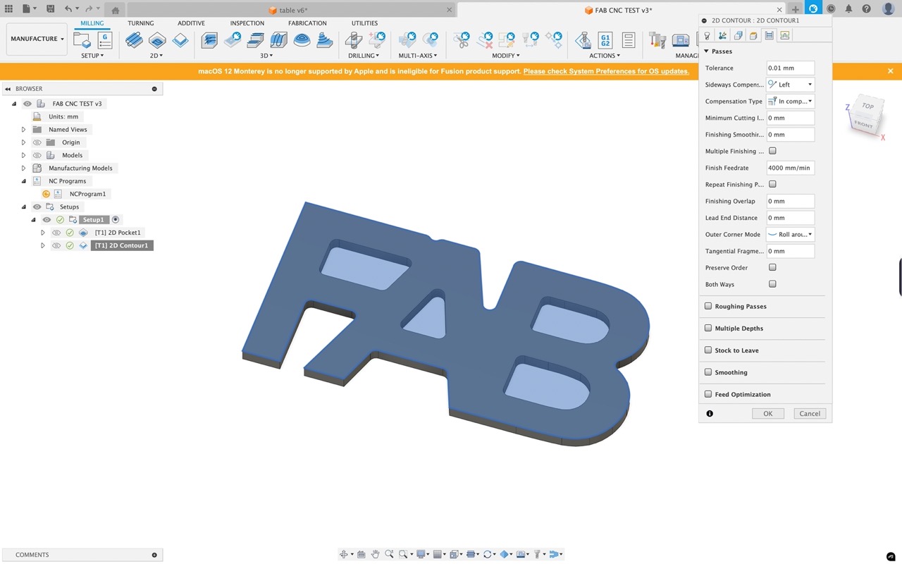
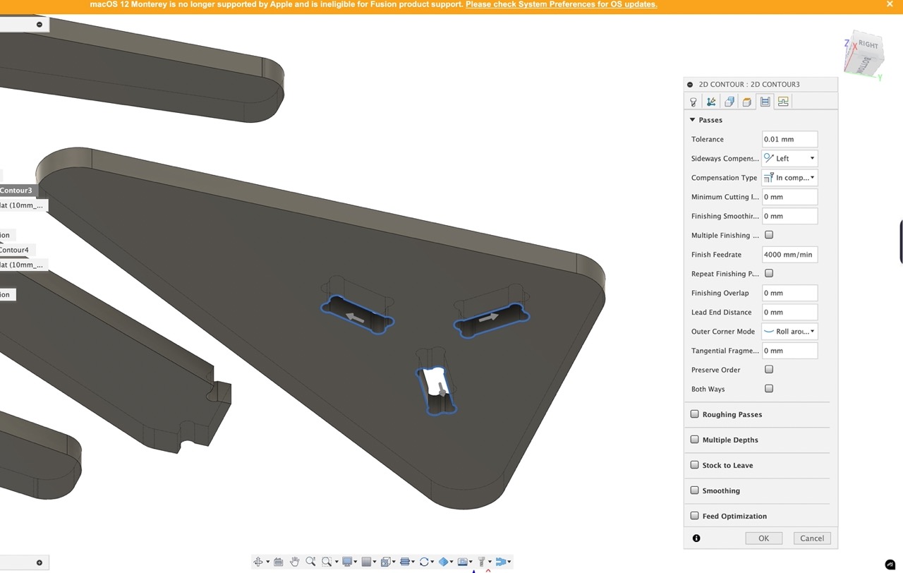
In the next tab we can set our preferences for the cutting passes
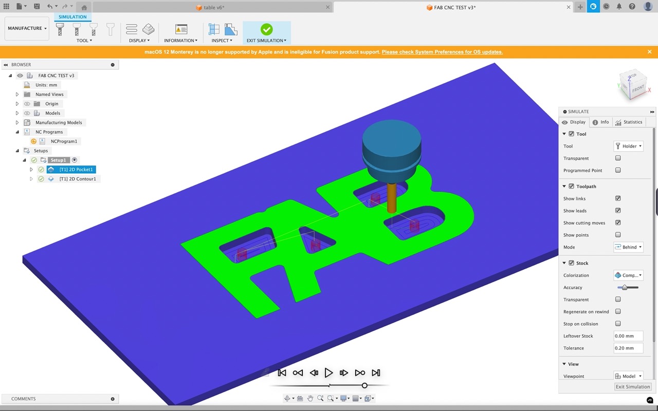
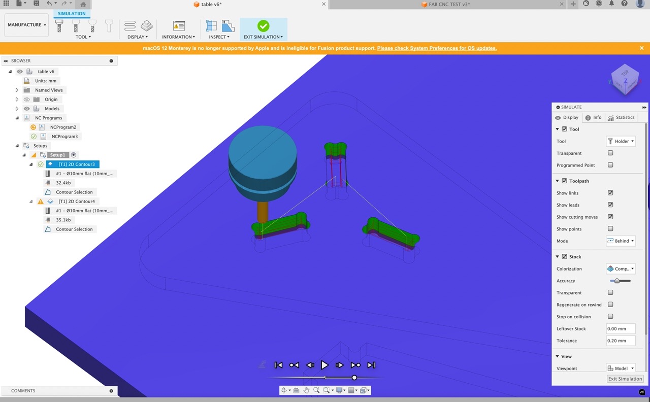
Click OK, the cutting toolpath will now generate - if we right click on the cutting path in the browser we can simulate the toolpath.
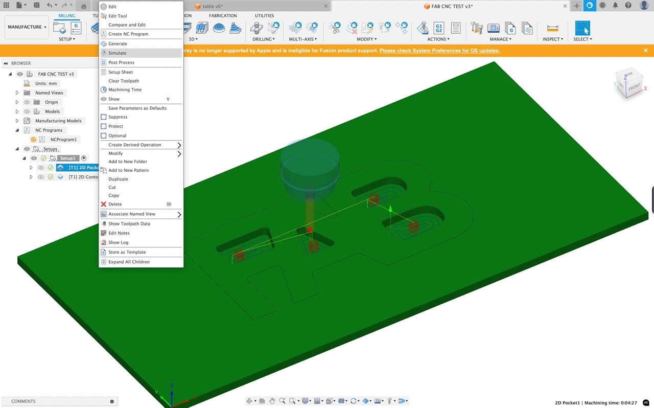
The play button at the bottom of the window will simulate the cutting toolpath - the slide will speed up and slow down the playback - in the dialogue window make sure stock is ticked and we can also visualise our stock material.
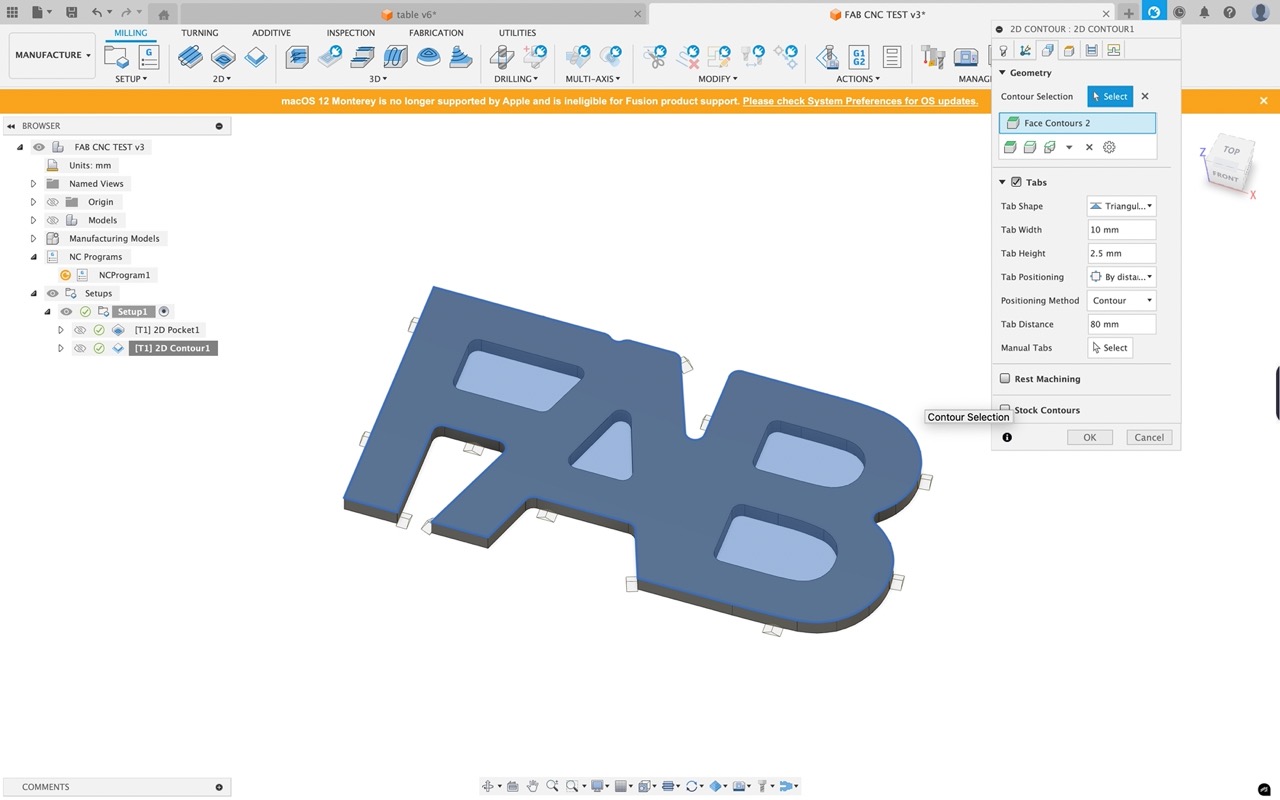
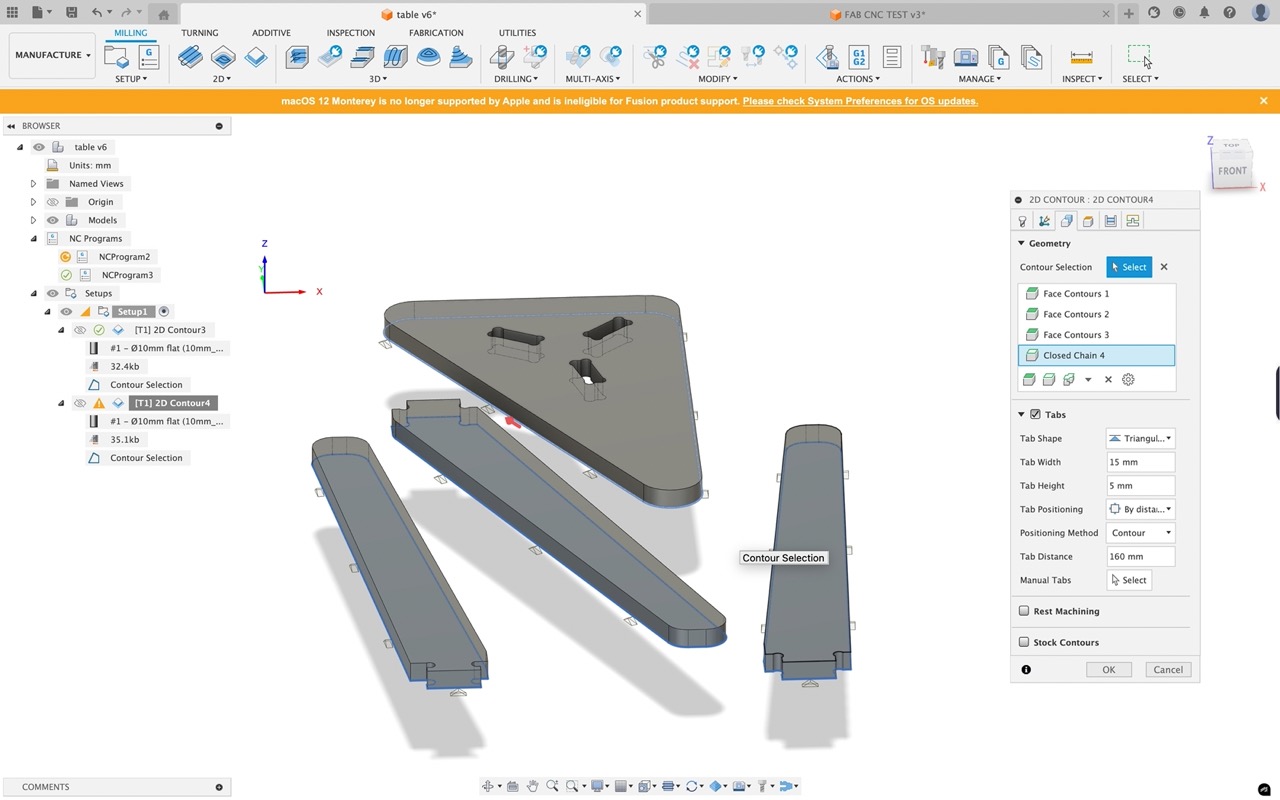
We can now select 2D contour from the 2D menu bar - select the face of the part - again choose the 10mm endmill (or whatever tool you plan to use) we can add tabs to the part so it will be held in place in the stock after cutting.
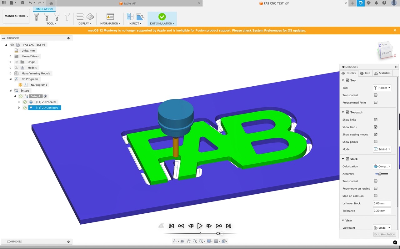
Once complete we can again simulate the toolpath to confirm everything looks correct.
If you're happy we can right click on the setup and go to postprocess - a new dialogue window opens -
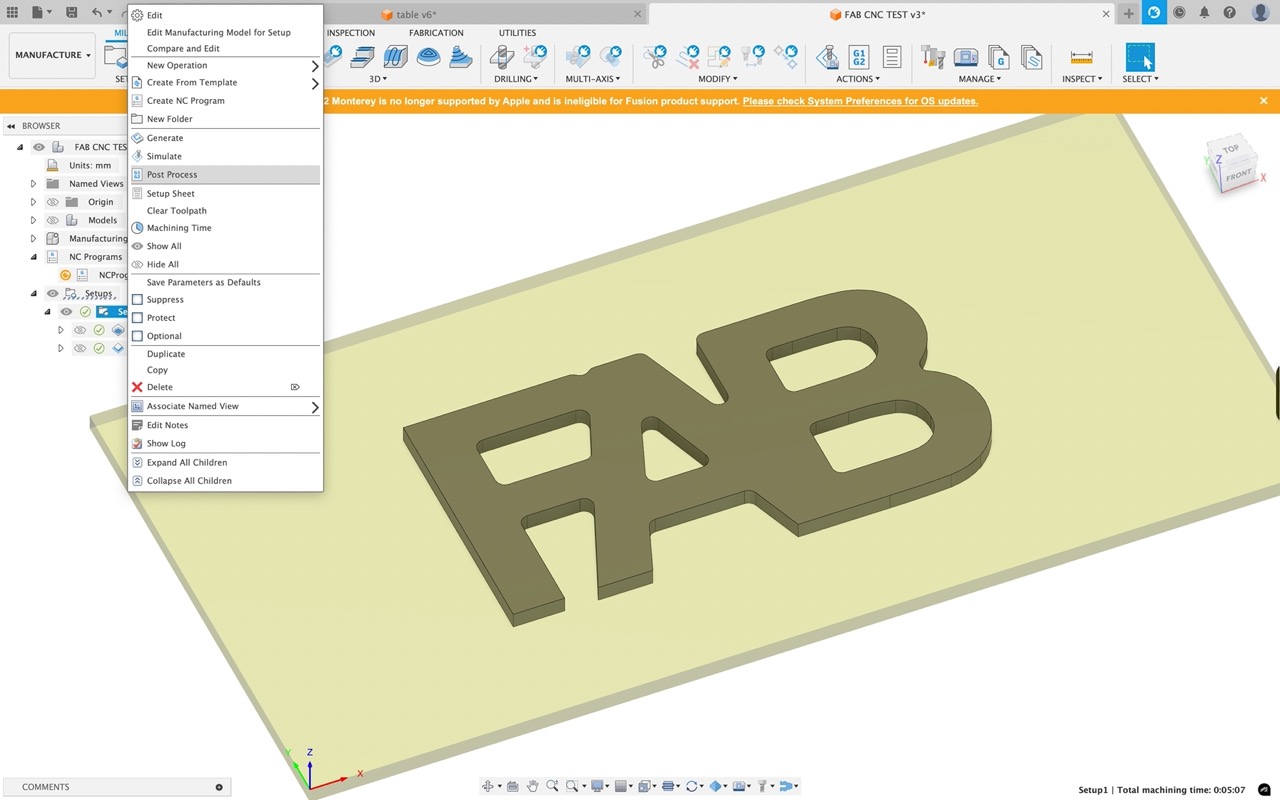
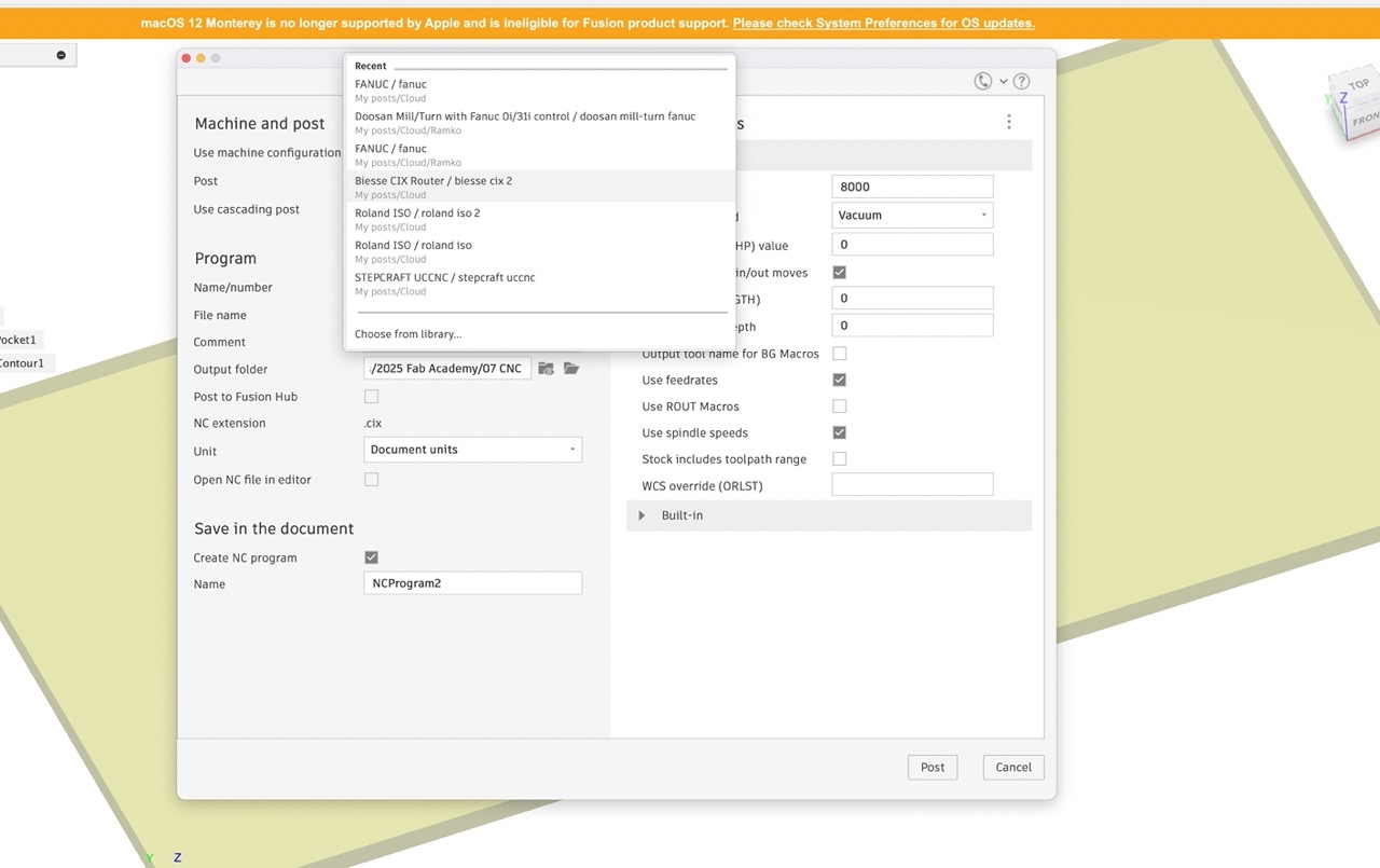
Select the machine we will be using - in this case the Biesse Rover. You may need to choose from library and search for your CNC machine.
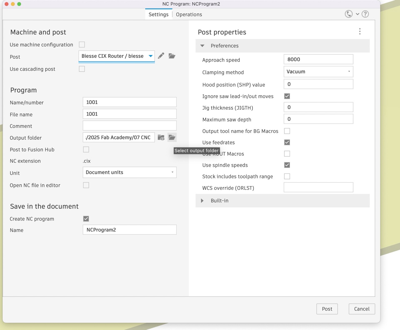
Set the programme number - this needs to be numbers only - you also need to set the Folder the output file will be saved to - click OK
We can save this to USB and take it to the CNC machine to cut -
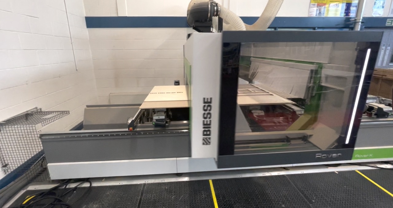
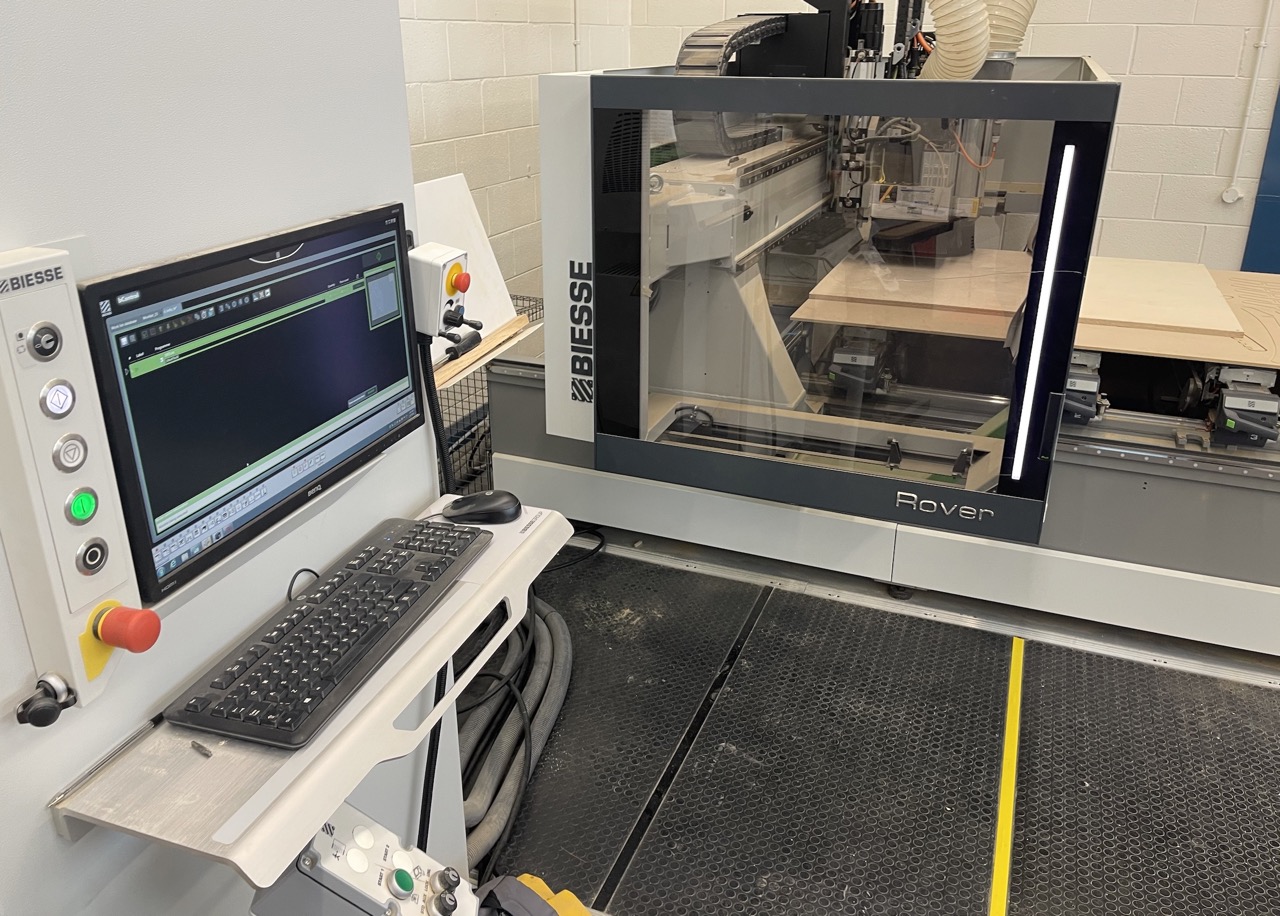
Biesse Rover
I decided to use equipment at South West College this week to produce something big as this would be more beneficial to me, my colleagues and students at the college. I had a few options: the Balstreni Idea 5-axis CNC at the Omagh Campus or the Biesse Rover at the Dungannon Campus. I specifically wanted to design the parts and produce the CAM toolpaths using Autodesk Fusion. I chose to use the Biesse in Dungannon as there was an available post processor for Autodesk Fusion – I would also like to use the 5-axis machine in Omagh. However, it looks like a post processor would need to be produced for this.
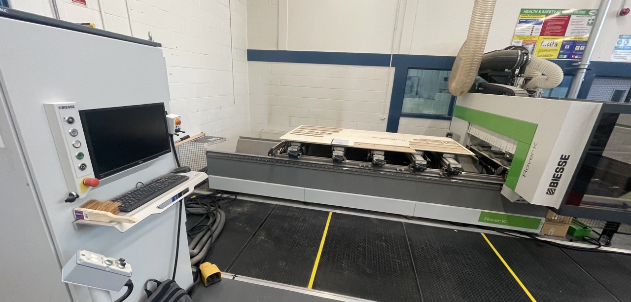
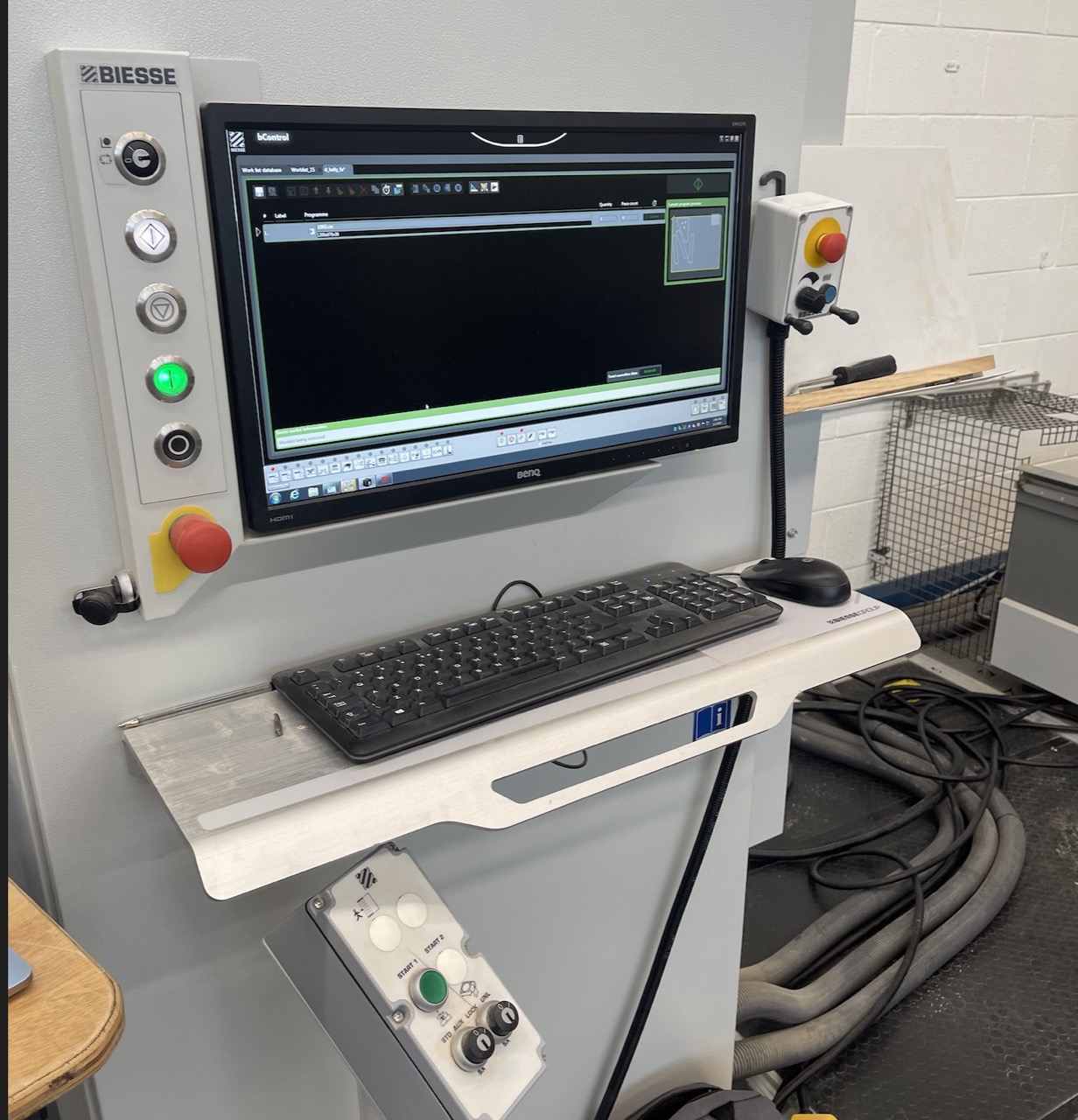
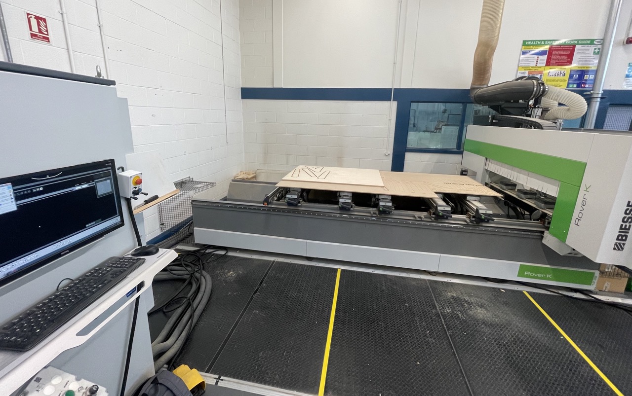
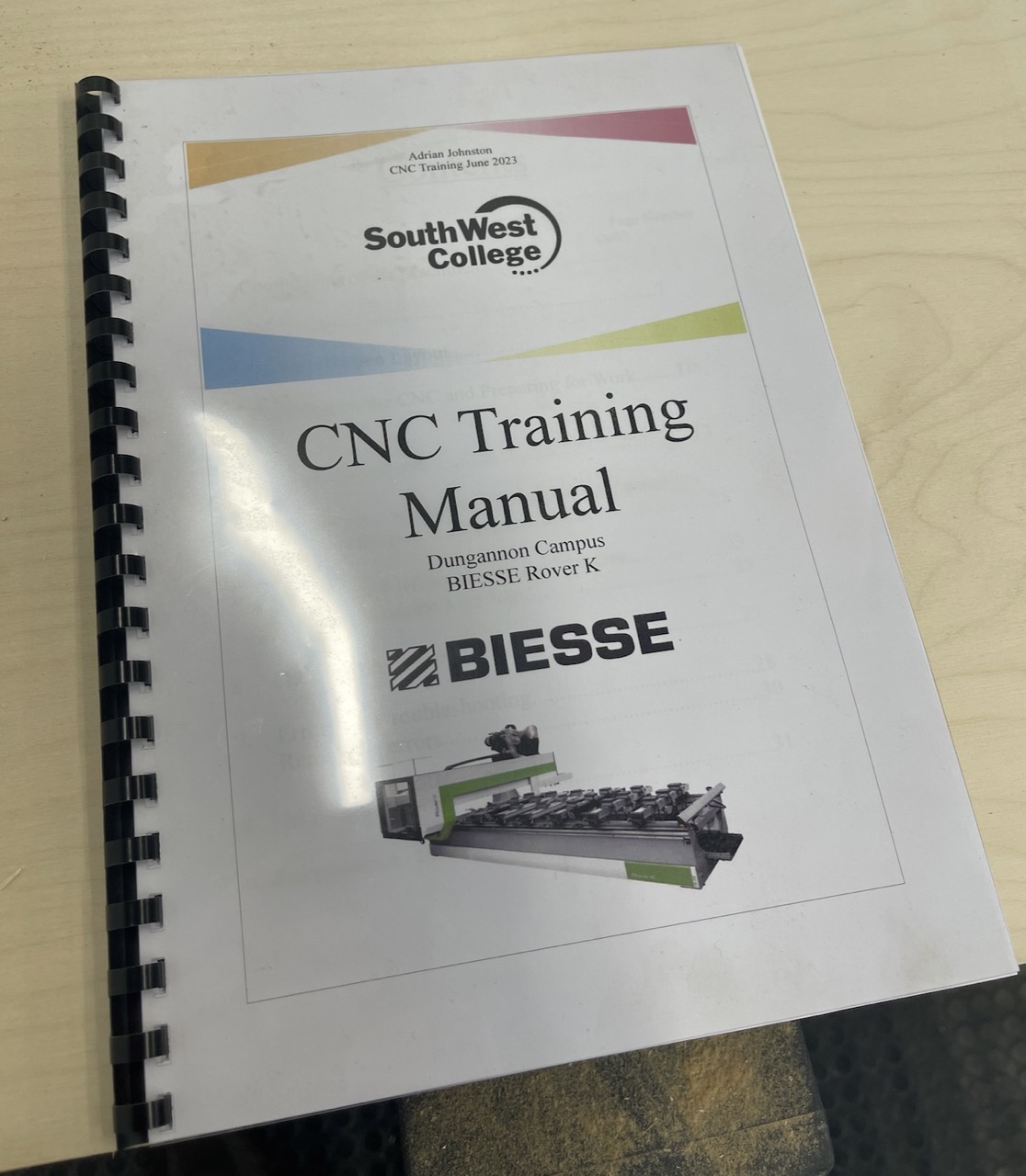 First, I read the college training manual for the CNC and familiarised myself with it, the operation of the machine and, most importantly, its safety features.
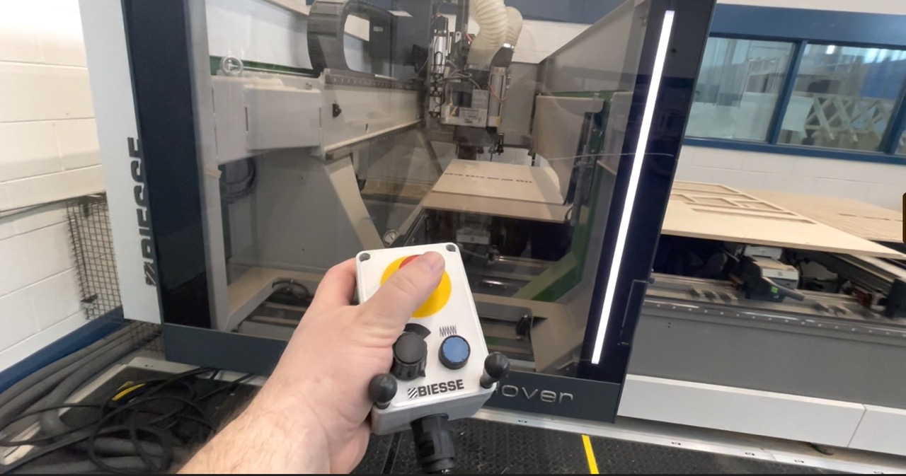
This machine had two red safety stop buttons, one beside the monitor and the other on the handheld console. There is also a safety mat in front of the CNC. This also acts as a safety stop – if you step into the mat while the machine is in operation, it will stop whatever the machine is doing – errors will need to be cleared in the computer, and the process can then be resumed by pressing the green button.
First, I read the college training manual for the CNC and familiarised myself with it, the operation of the machine and, most importantly, its safety features.
This machine had two red safety stop buttons, one beside the monitor and the other on the handheld console. There is also a safety mat in front of the CNC. This also acts as a safety stop – if you step into the mat while the machine is in operation, it will stop whatever the machine is doing – errors will need to be cleared in the computer, and the process can then be resumed by pressing the green button.
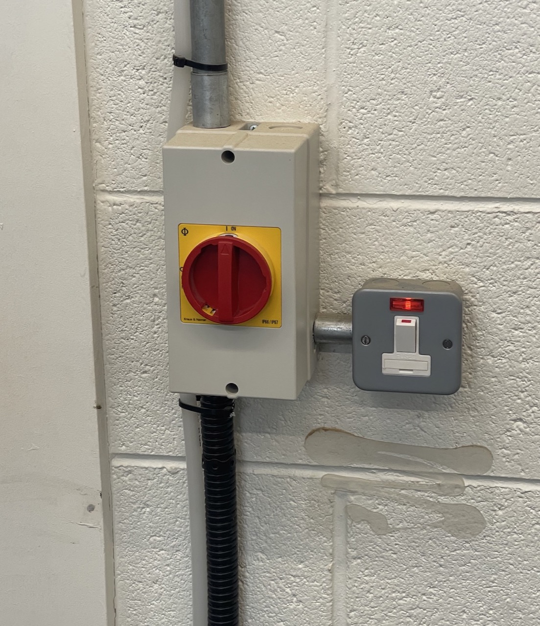
Let's get started by powering on the CNC.
Power on the wall switch isolator and flick switch
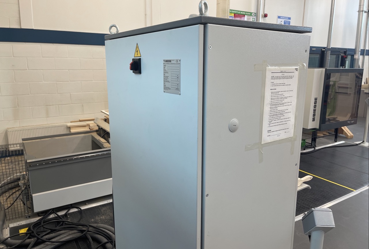
 The switch at the back of the console cabinet will power on the CNC and computer.
Let the machine switch on and the computer boot up
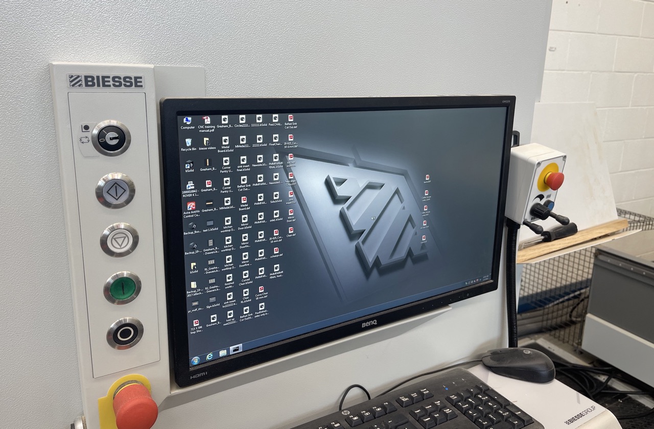
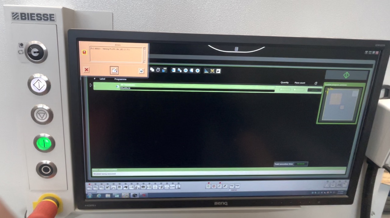
After boot up, the "QUOTE" window/dialogue should open up
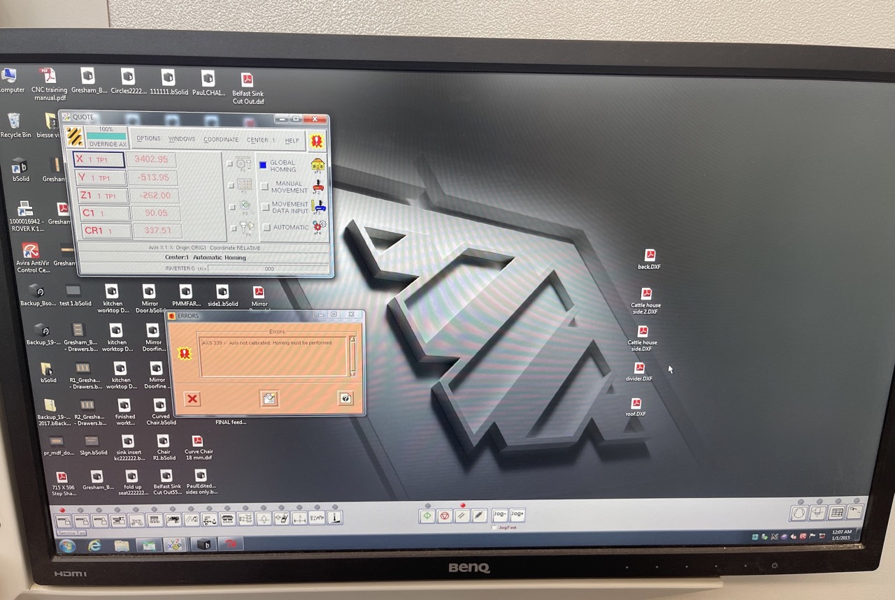 There will also be screens with errors on them – we can clear what we can by pressing the "clear errors" button – however, we also need to home the CNC to allow all the errors to clear
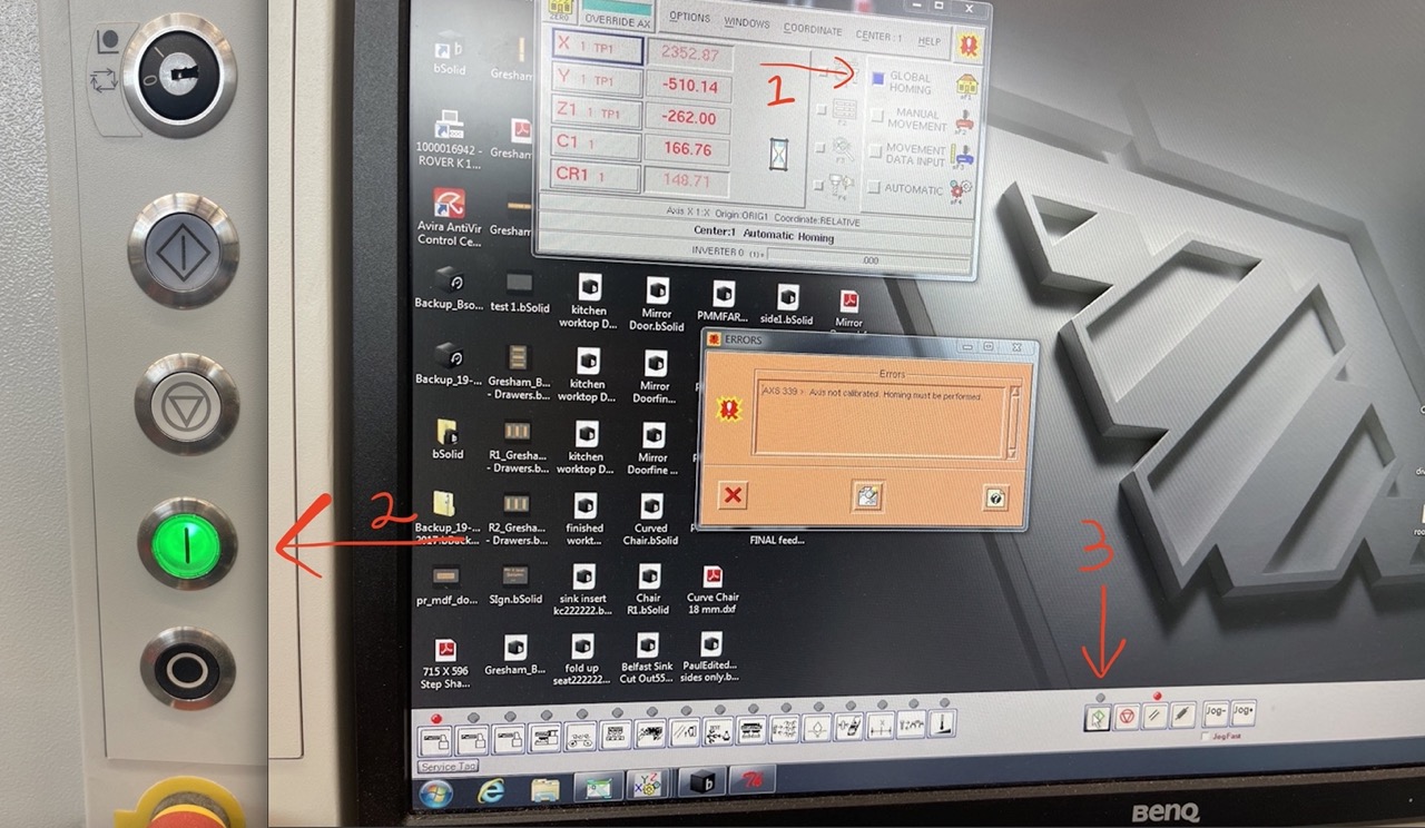
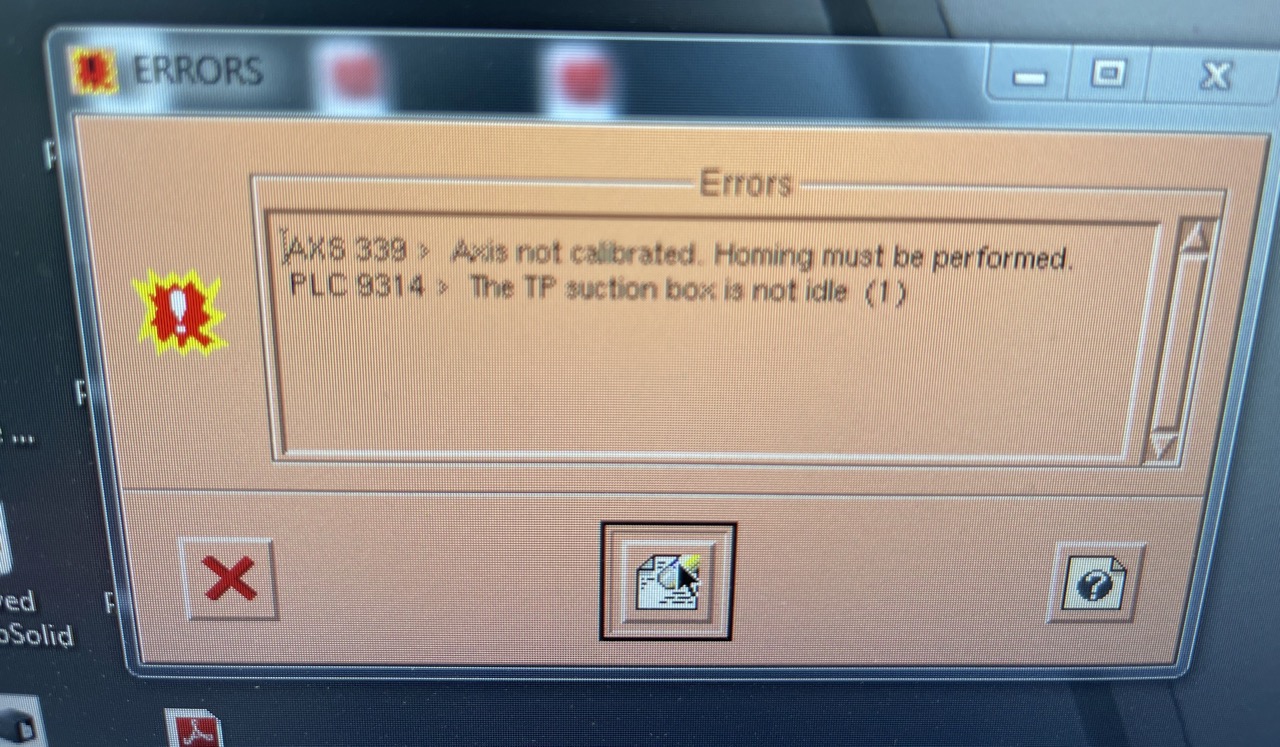 (1) In the QUOTE dialogue, make sure global homing is selected, indicated with the blue square to the left. – (2) Press the lower power button to the left of the computer screen and wait for it to go solid green – (3) Press the green start button in the computer, bottom centre of the screen.
 The Machine will now Home – while this is happening, do not step on the pressure mat - when this is complete, we should be able to start cutting -or get our test pieces uploaded to start cutting –
 At this point, we can take our output toolpaths from Autodesk Fusion and bring them into the CNC machine.
Setting up parts to cut in BSolid
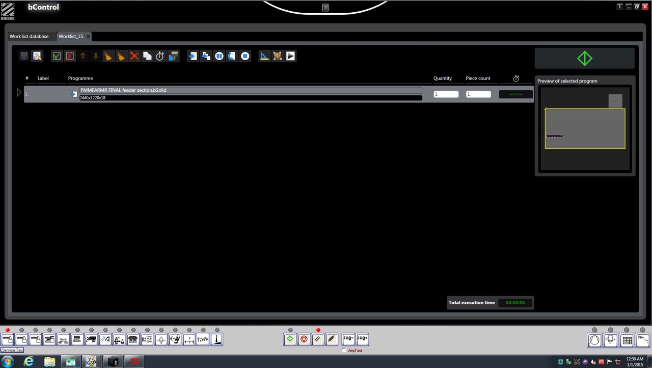
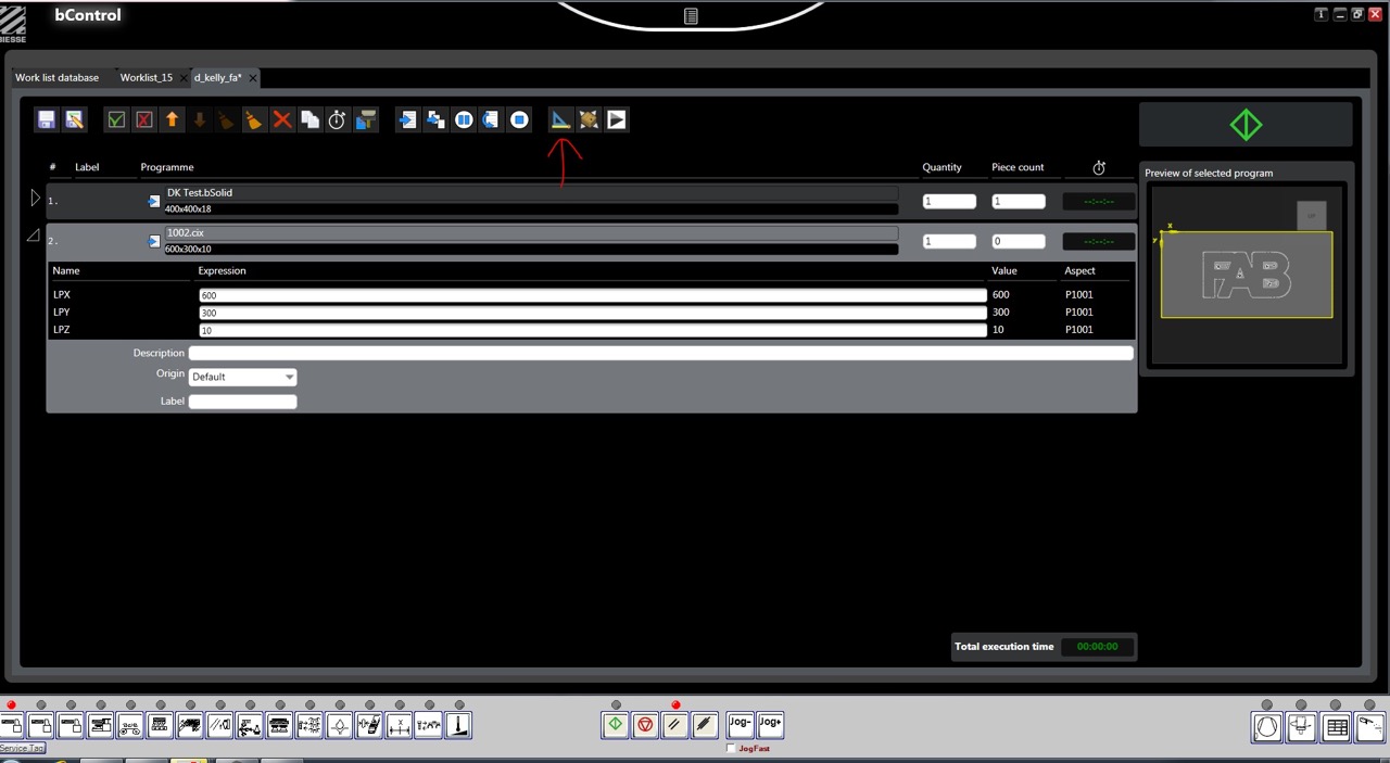
I opened a test part created in BSolid to check the CNC machine was cutting as it should - I did find a 6mm bit was broken when I got to the CNC so I knew this cutter could not be used. In the work list, add file – I opened a test part that had been run on the CNC before.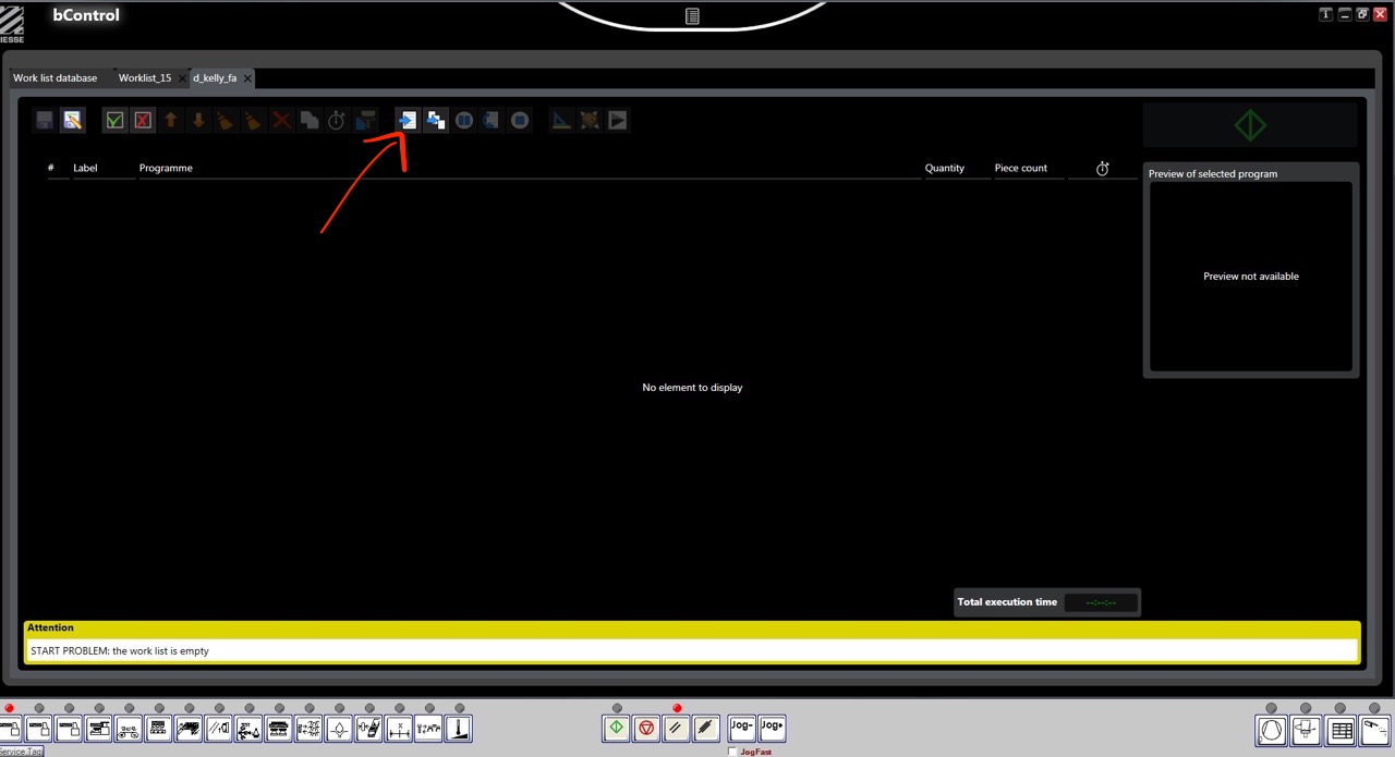 This then adds a file to the work list – we can inspect this using BSolid and change parameters if needed.
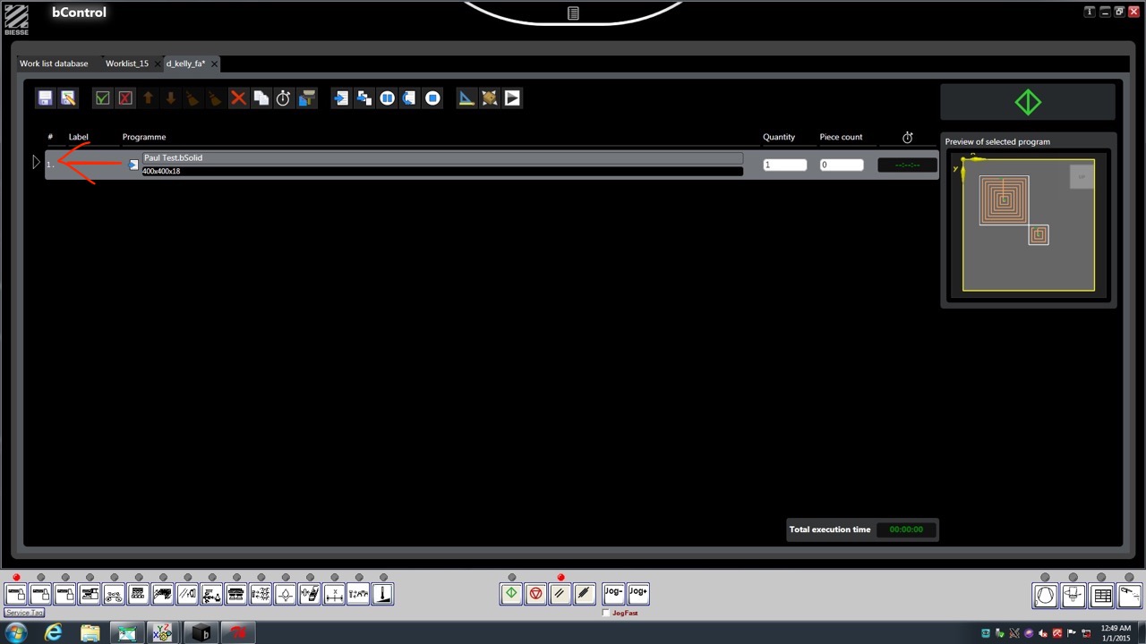 Press the arrow to the left to see details of the job, such as stock size and origin location. We will be using the default origin for most jobs.
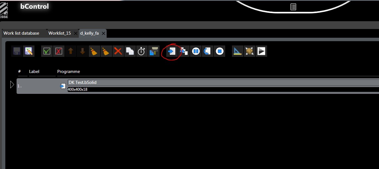
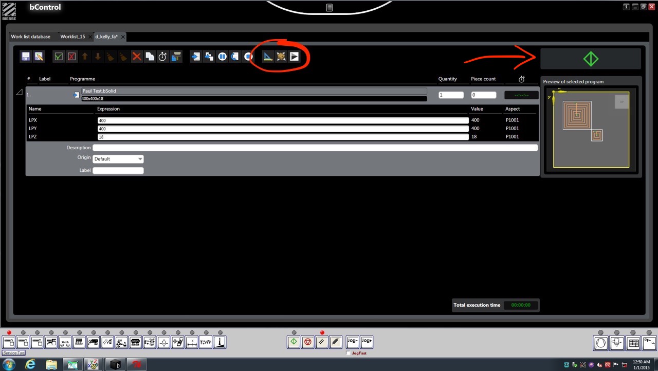 To edit or preview the job in BSolid we can use the icons at the top of the screen circled in the previous image.
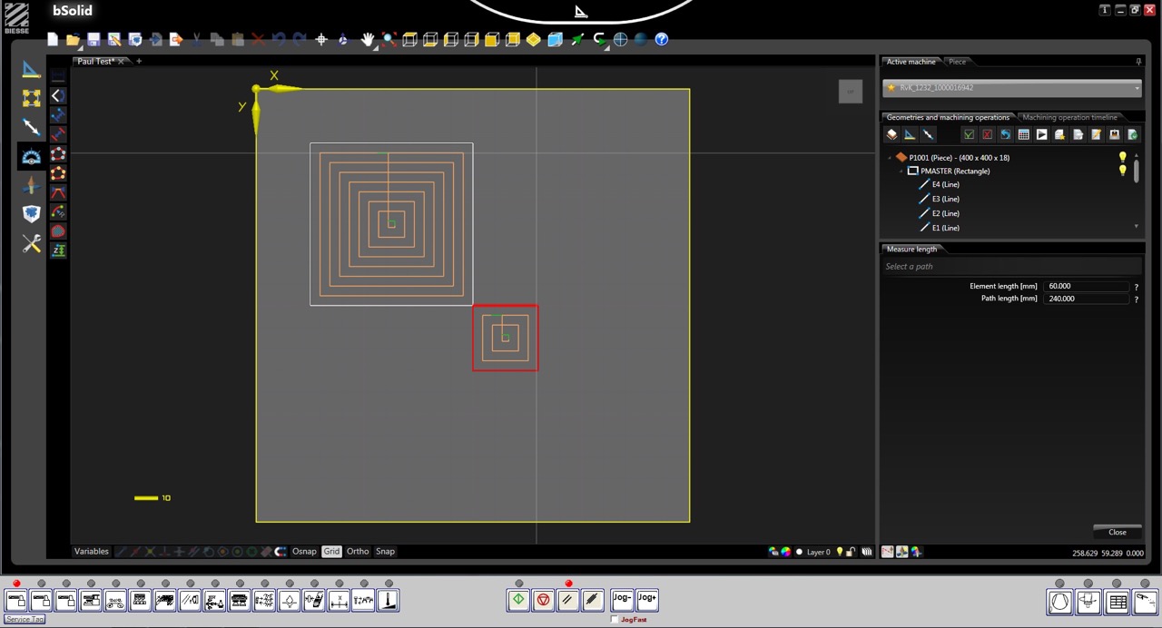
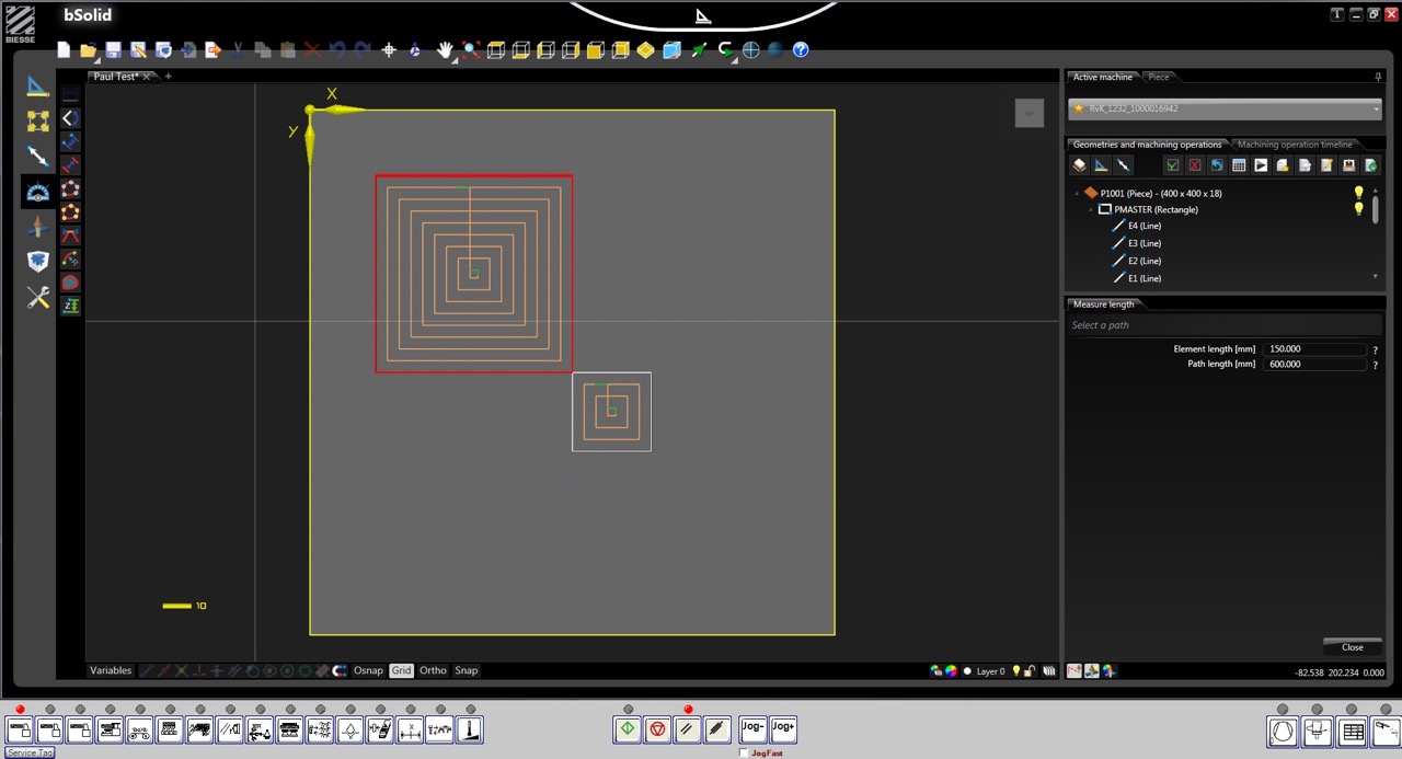
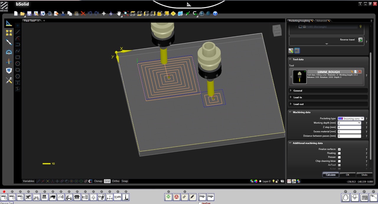
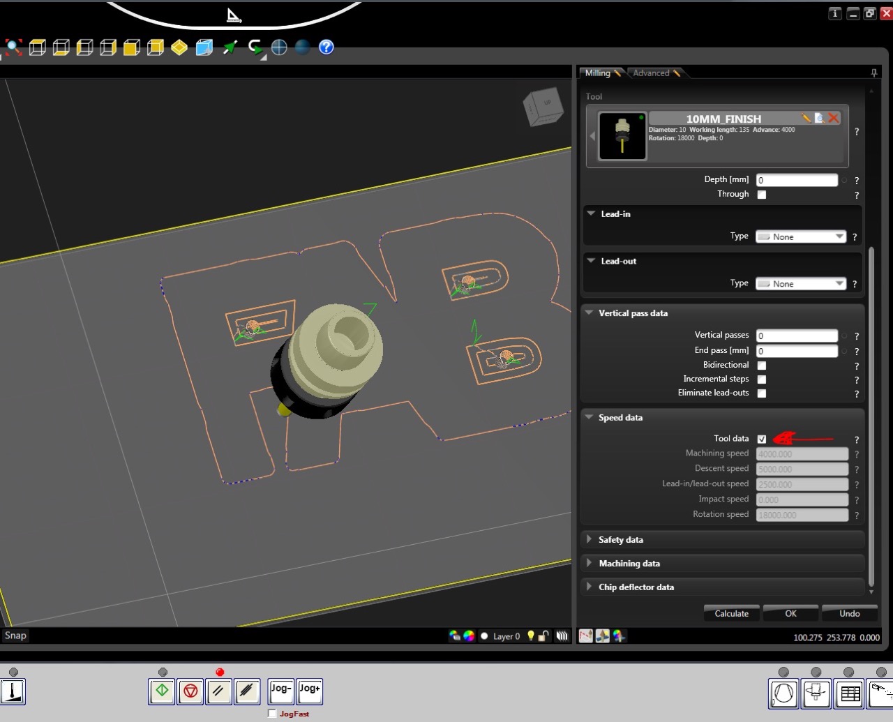
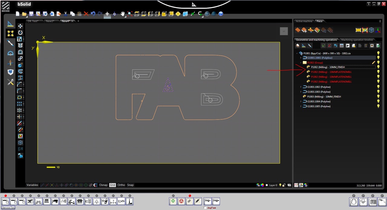
This will open the job in the CAD preview window where we can make changes to the toolpath and cutters used - in my case I had to select a 10mm cutter to replace the 6mm cutter that had recently been broken on the CNC.
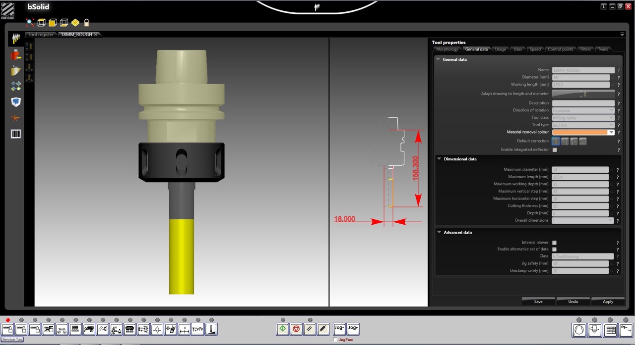
I opened the tool library and identified the 10mm cutter profile and added it to the job in place of the 6mm cutter, saved to file and returned to the work list.
To send the job to the CNC we just need to press the green button at the top right of the screen –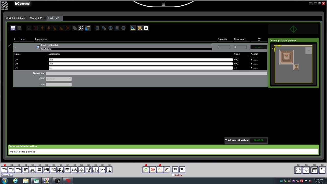 The programme has been sent to the CNC, and we can now load the material.
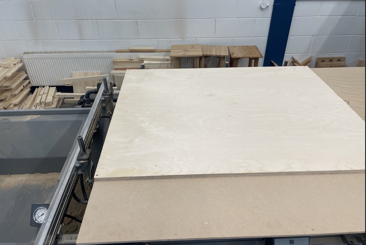
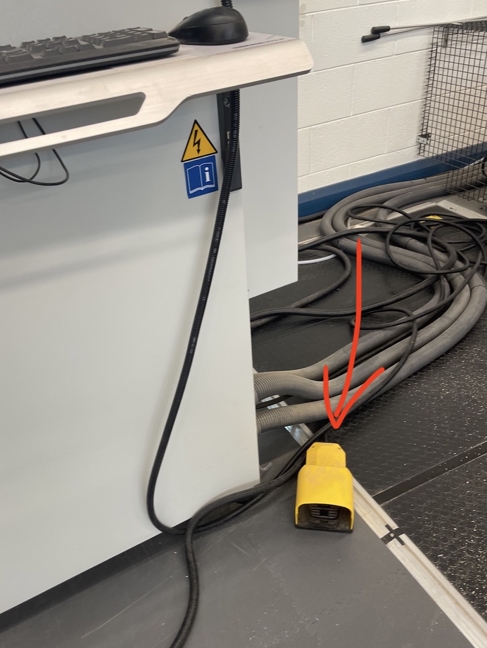
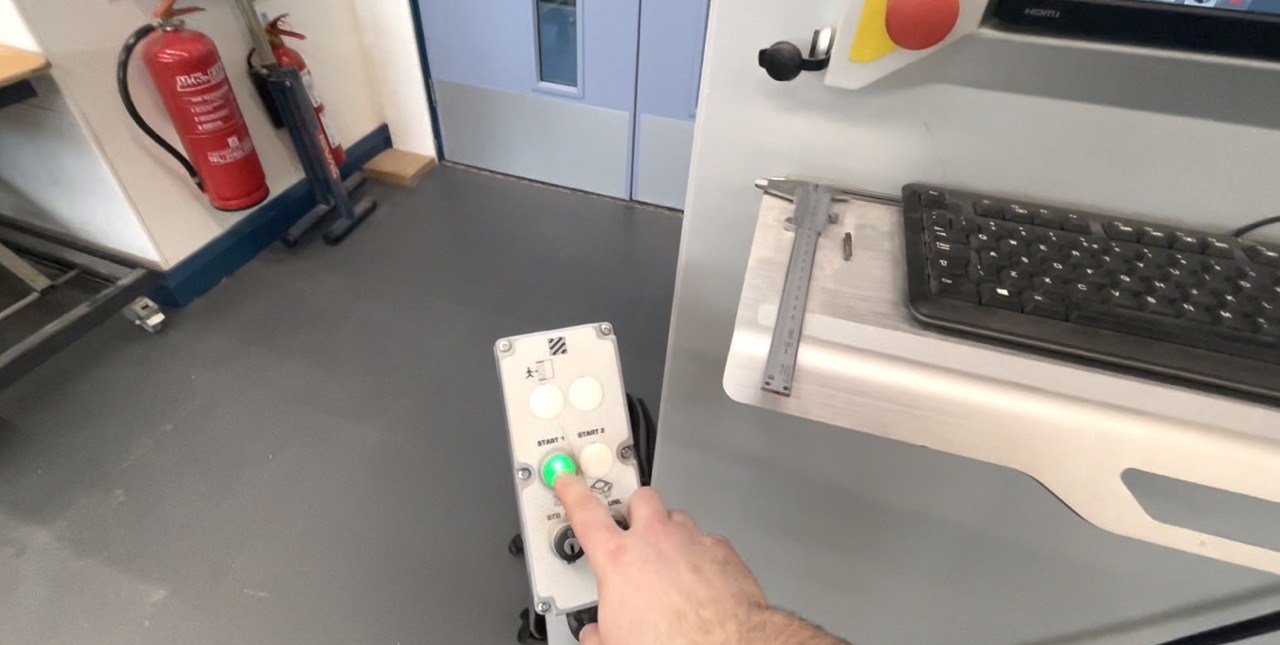
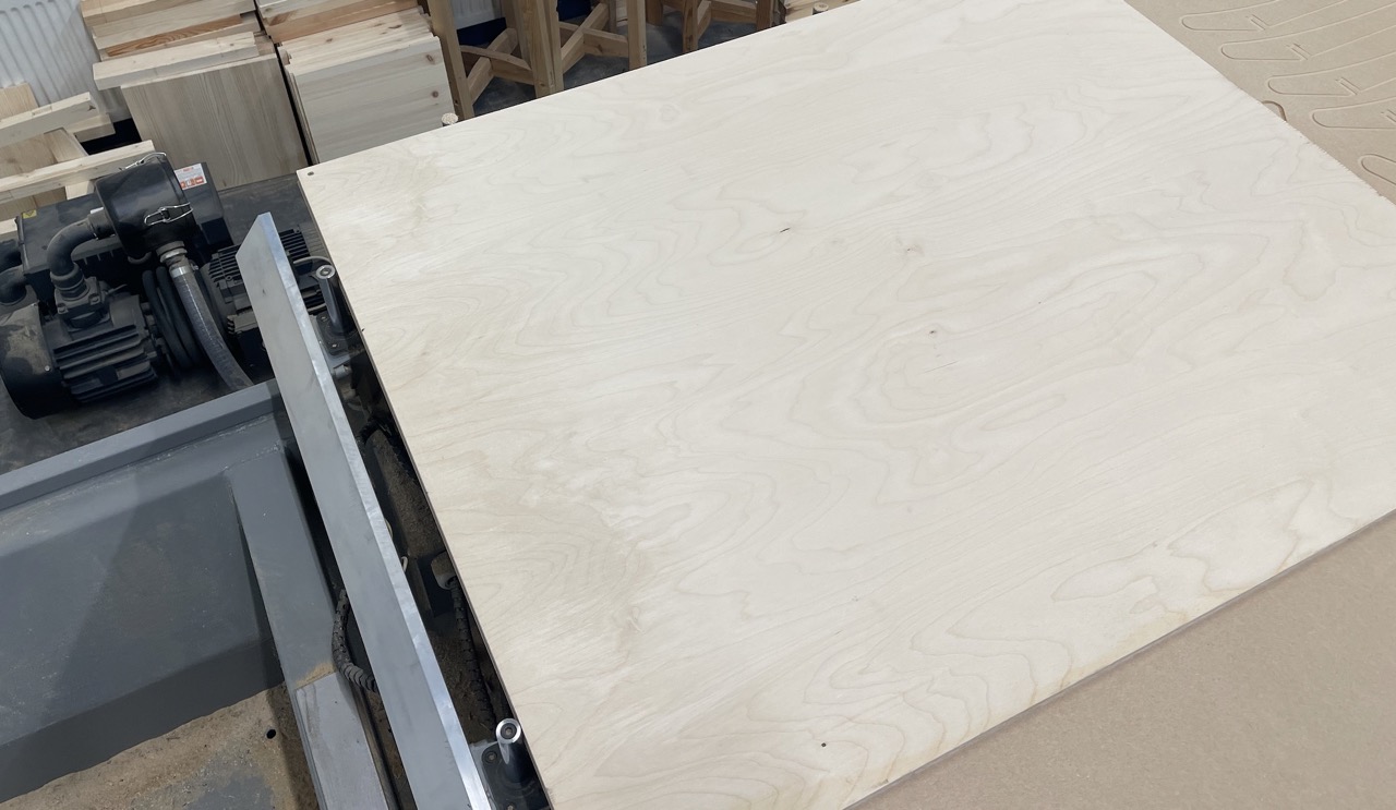
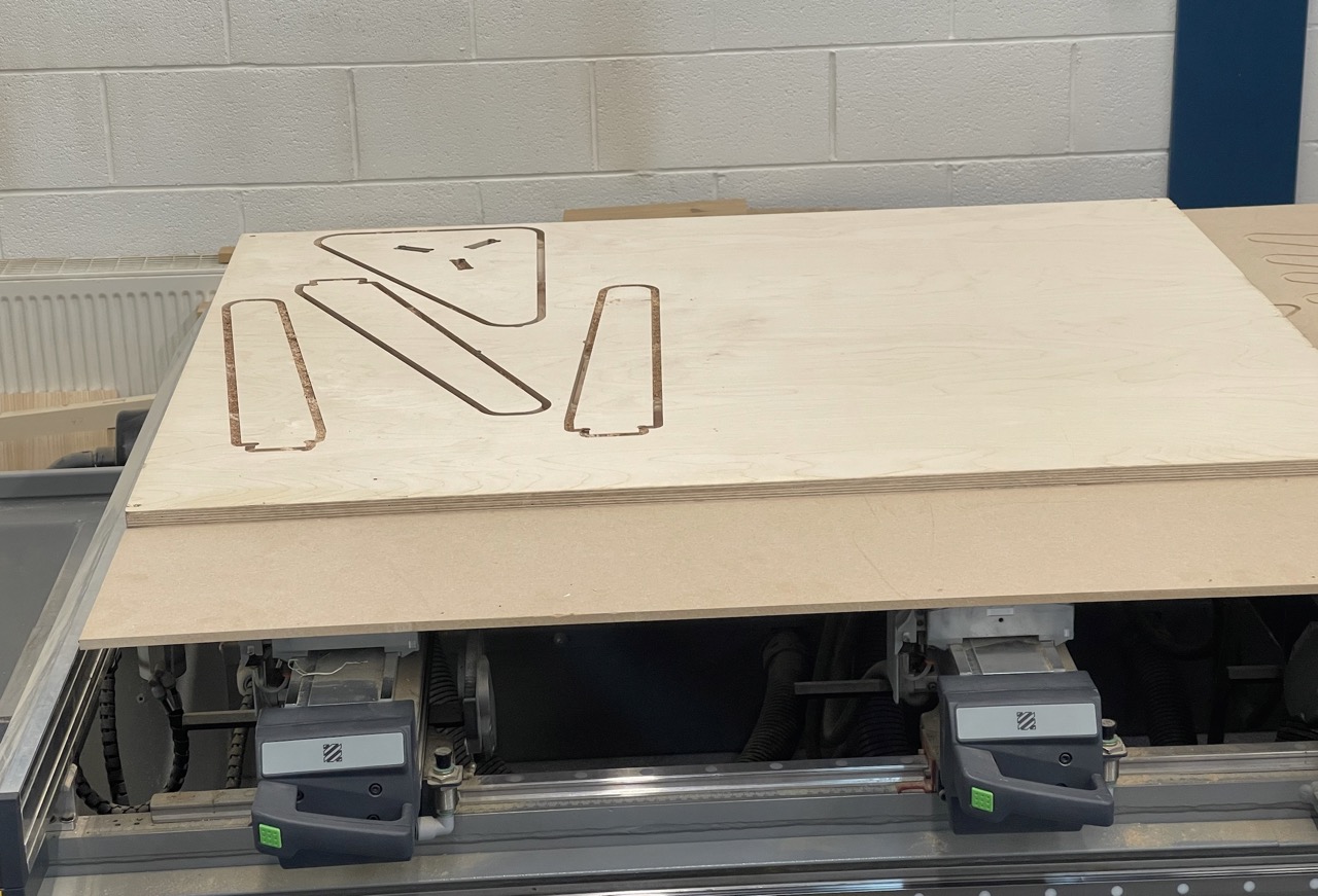
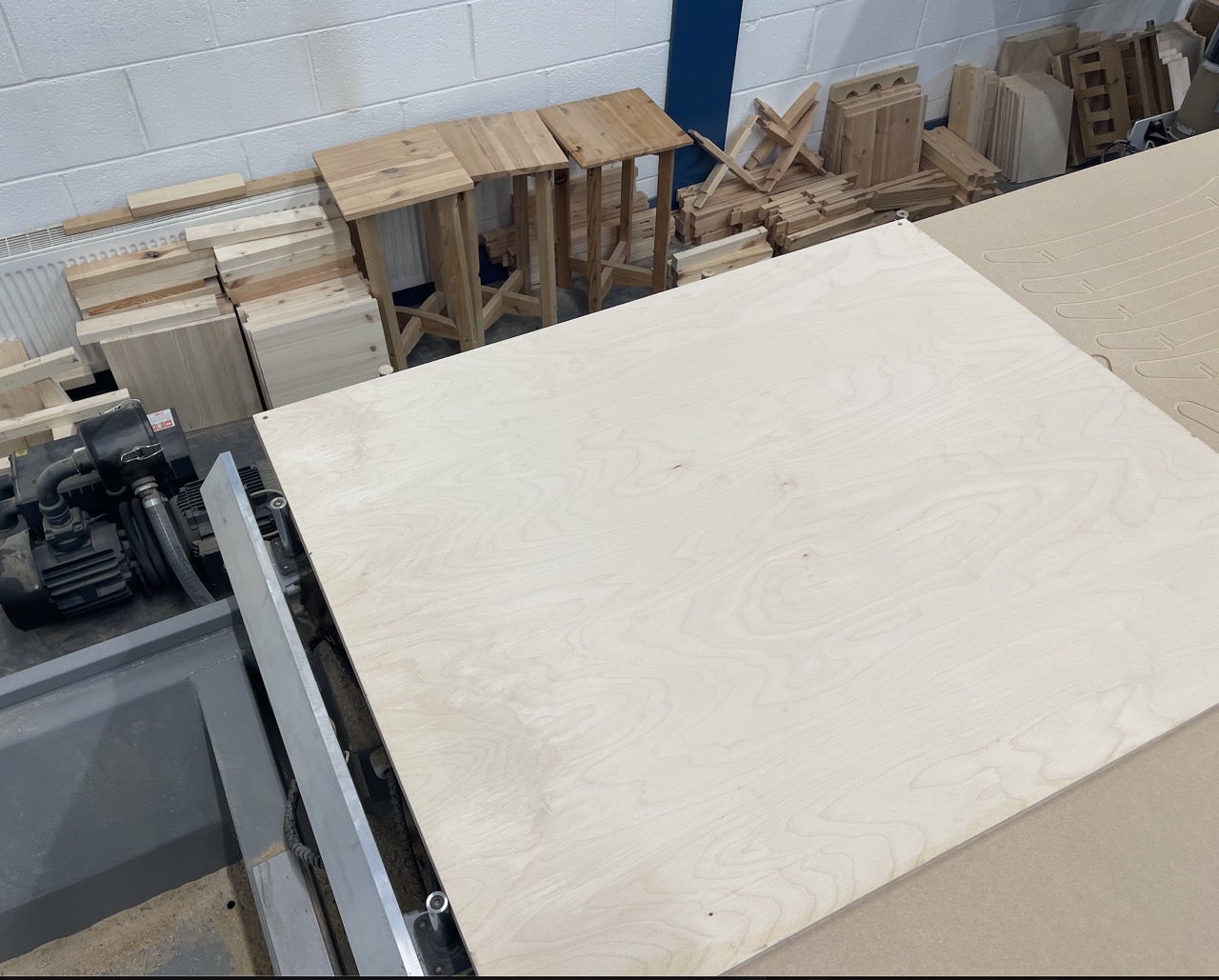 To load the material, press the green button on the floor console. This will lift the 4x large guide bars, we can then place the stock material onto the pods and up against the bars. Press the foot pedal to activate the pod vacuum.
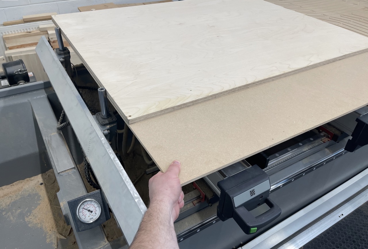 The stock is now loaded, you must check to make sure it is securely held if not you might need to give it a tap with the side of a clenched fist.
 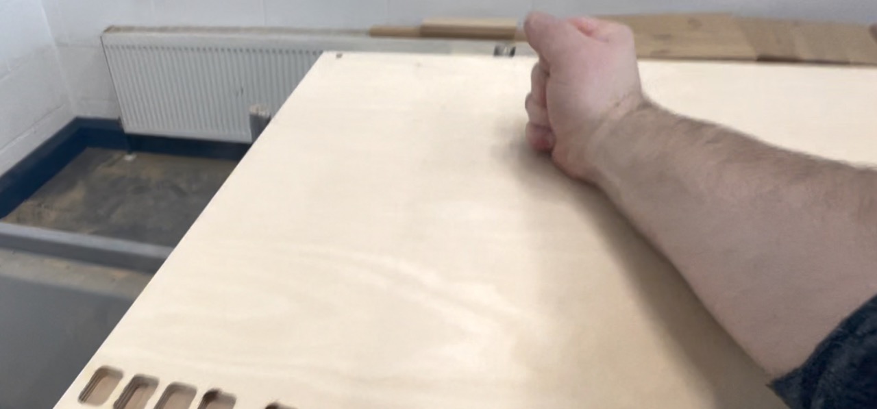 We now need to clear the errors again as we were standing on the safety mat.
We can press the green button on the floor console to start the CNC machining process.
The CNC will now move to start cutting - stay off the safety mat and at this point it's a good idea to grab the hand console and get ready to hit the red button – also make sure the speed controller is at full speed – if it's low or all the way down it will cause the machine to run too slow and damage the tools and potentially cause a fire.
At the start I'm looking closely to make sure the cutting tool isn't going to plunge through the material into the pods and that it's cutting at a high enough feed rate.
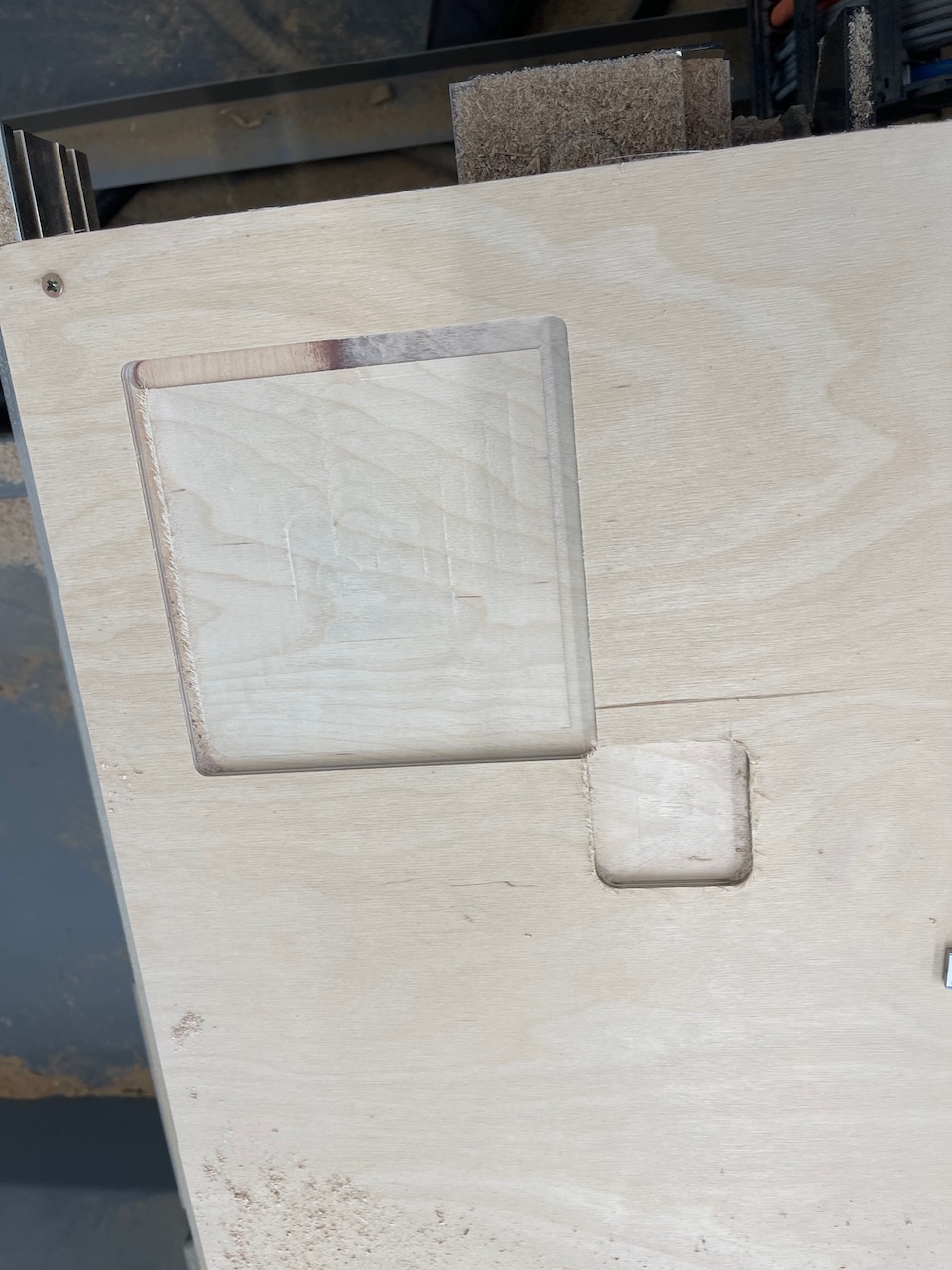 Once the part is cut we can check the dimensions to make sure it is within the tolerance of the design. So far so good. Let's get on with sending some parts from Autodesk Fusion
We can import the test piece we made in Autodesk Fusion to the CNC machine.
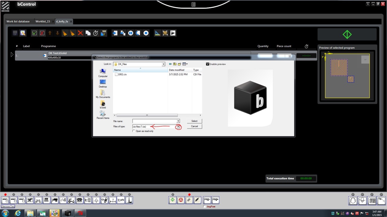
In BSolid select the import button from the menu bar at the top of the screen
Select the file you want to import - make sure the file type is set to CXI
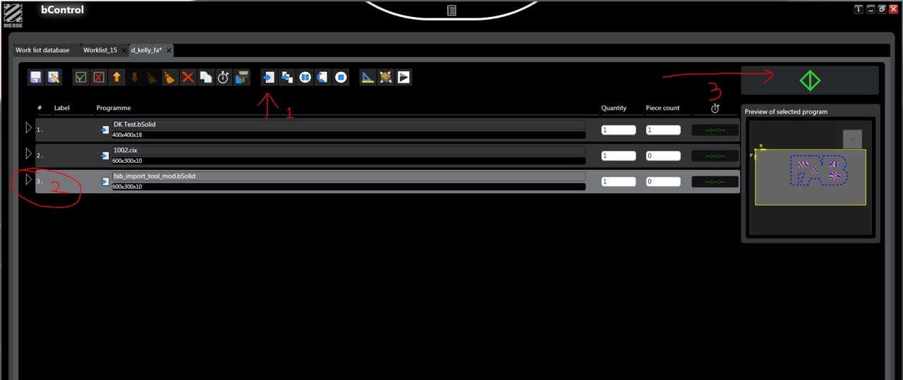
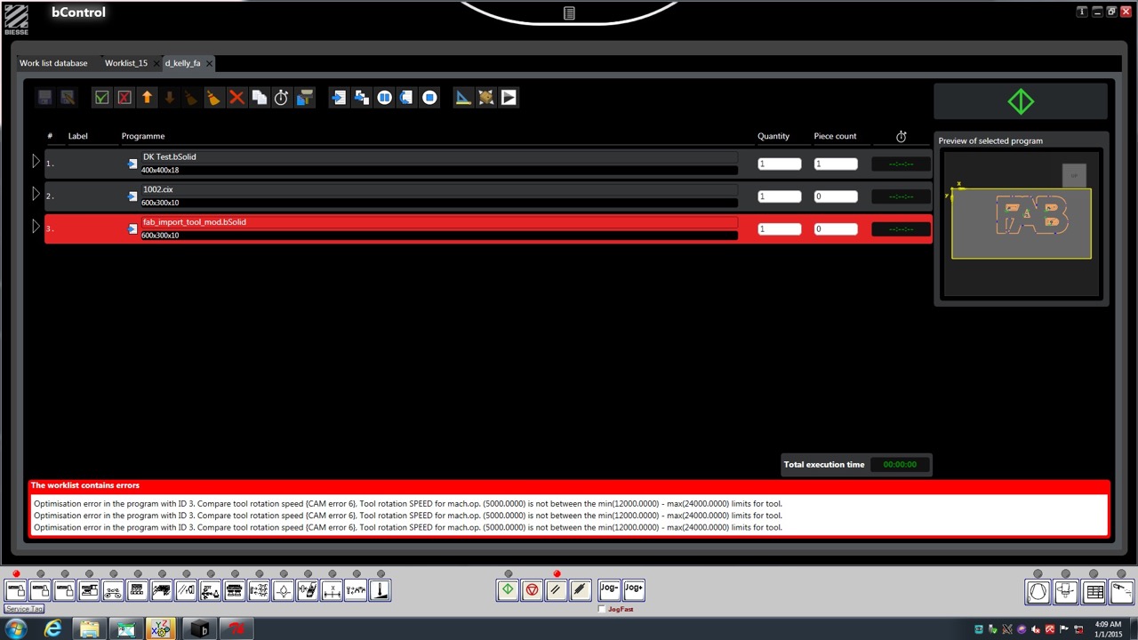
Once open it will be added to your work list - we can inspect this using BSolid and change parameters if needed.
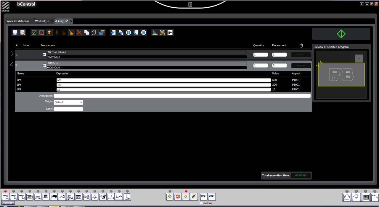
Press the set square icon to check parameters - if anything is changed it will create a duplicate in the job list - I changed the offset (I should not have)
I changed the tool offset (this was a mistake) and made sure the correct tool was selected
To get the part cutting follow the numbered procedure below once you hit the green button the machine will power up and start cutting be ready!!
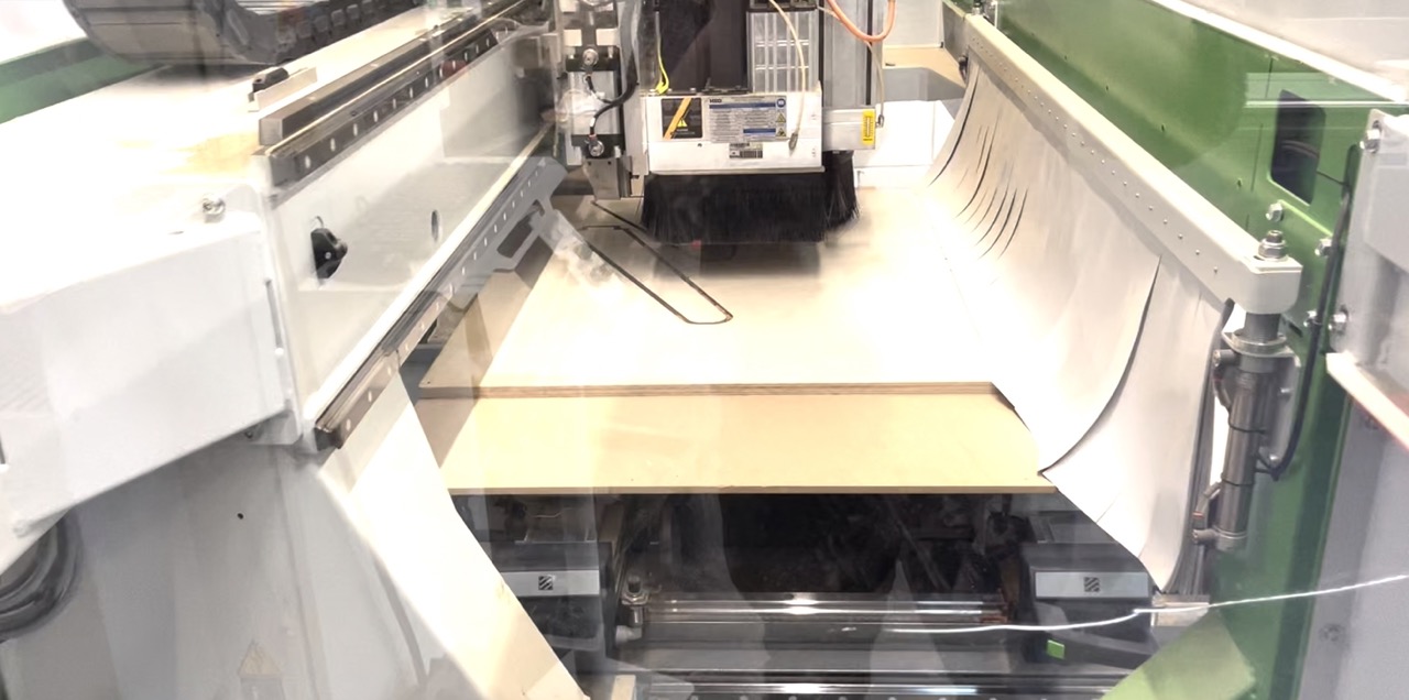
Above the CNC cutting the FAB part and below some images of the results
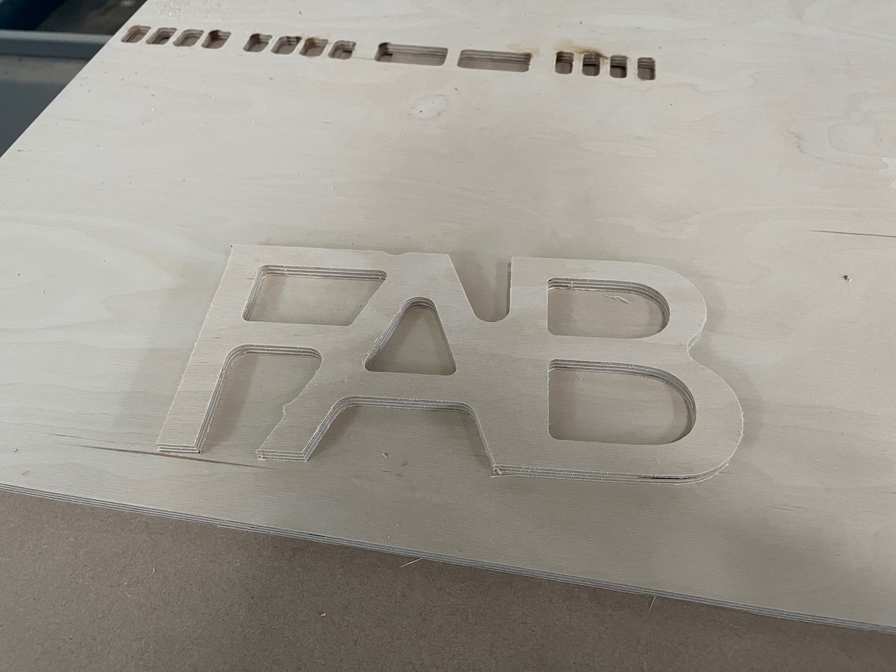
Design something big (using Autodesk Fusion) Cut using a Biesse Rover CNC
The below screenshots follow a very similar process to the FAB test part we machined, follow below.
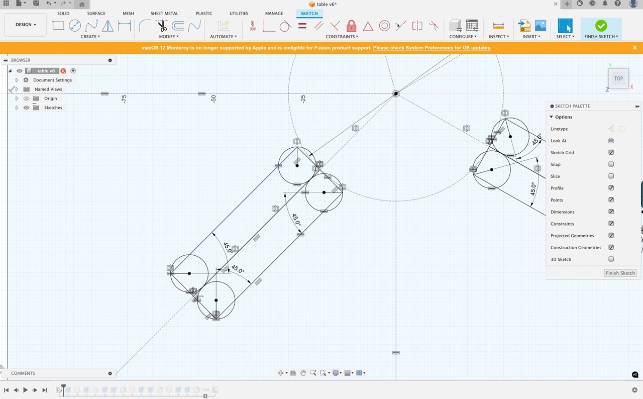
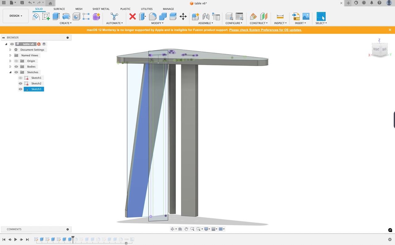
Start with a 2D Sketch
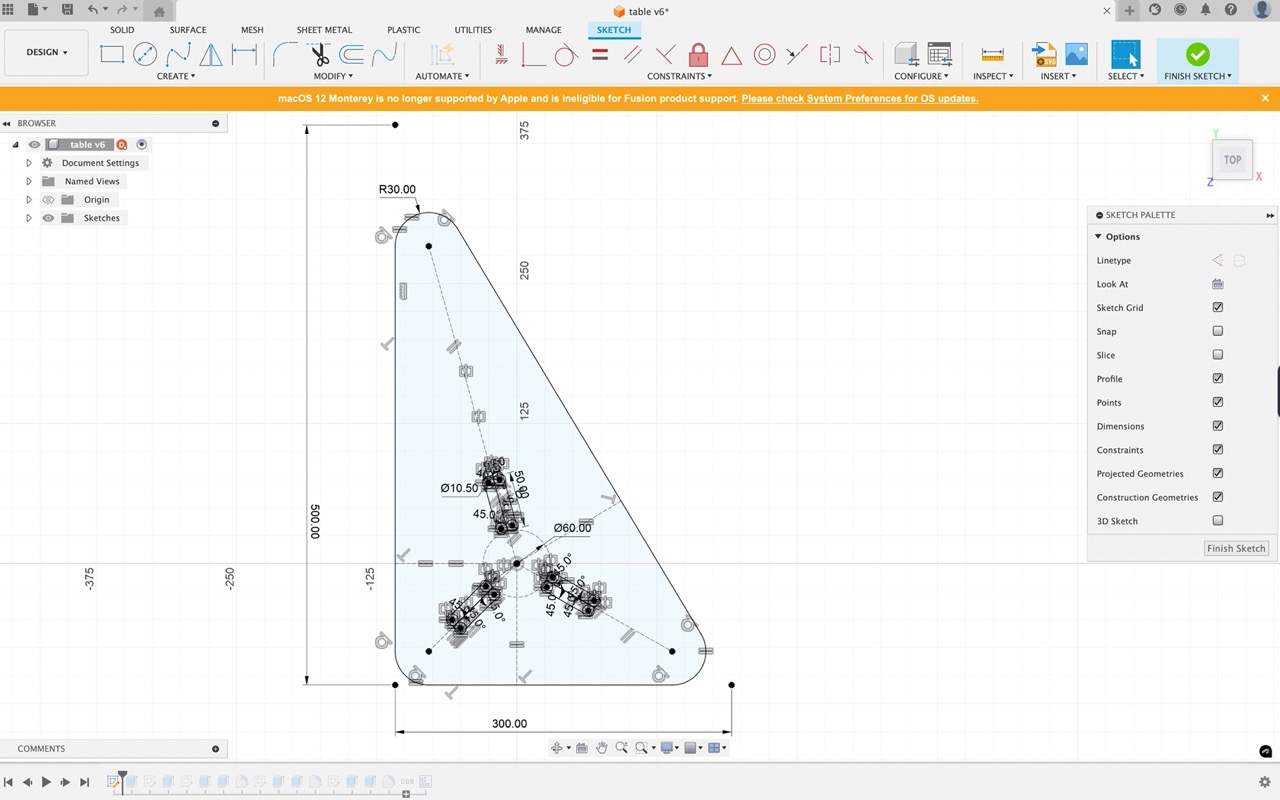
I added some dog bones to allow for the cutting tool - the parts will be square but the round cutting tool can't profile square corners - this is a quick solution
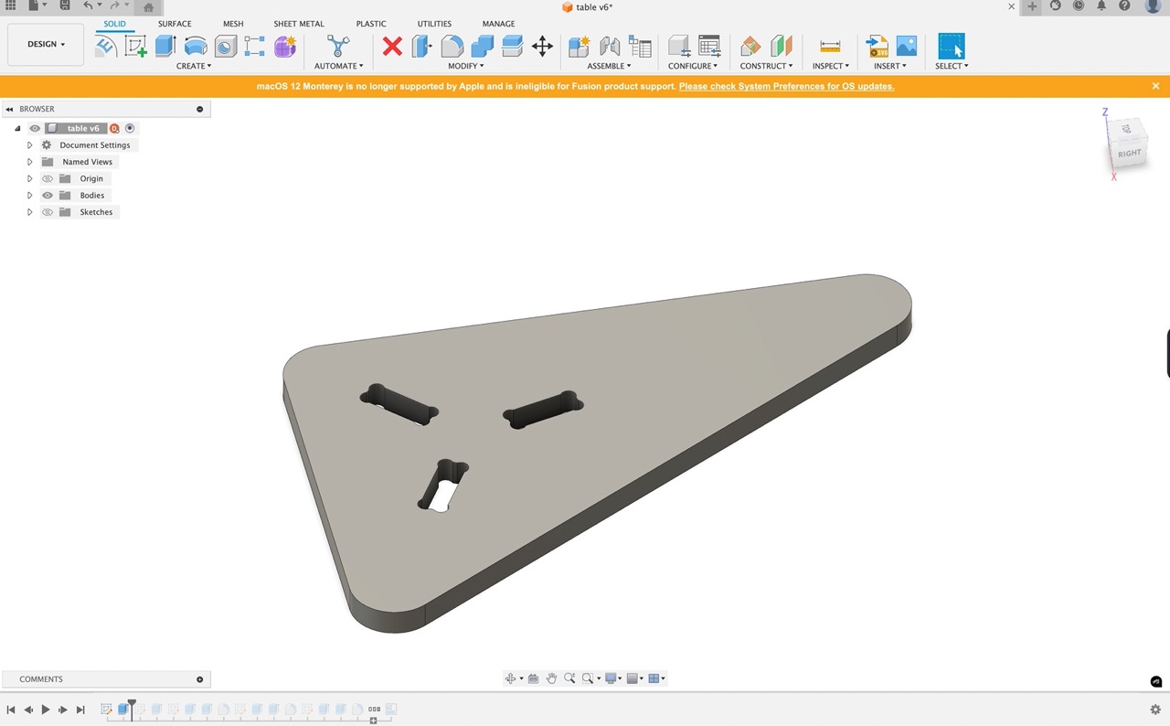
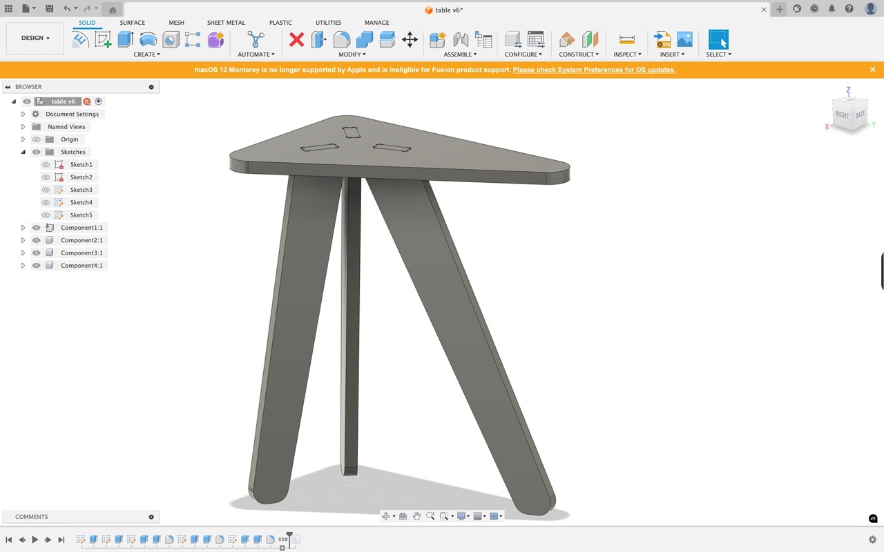
The sketch is extruded - for the most part I'm following similar process as described previously - follow the images below
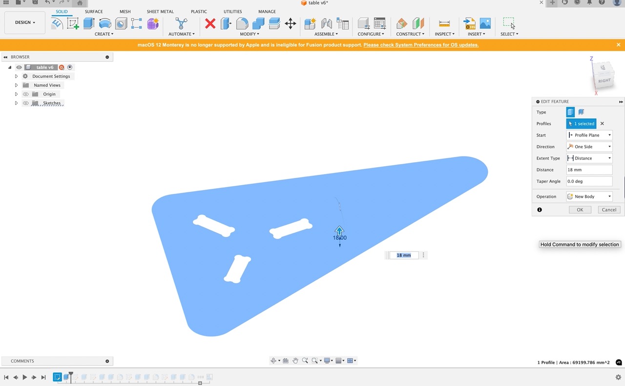
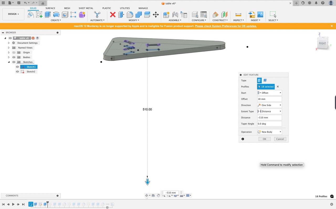
Table top is extruded to the material thickness
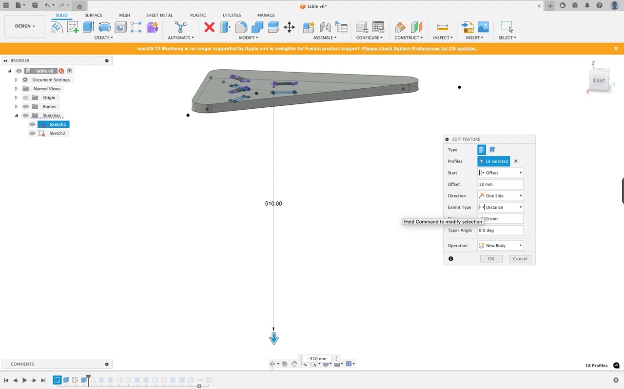
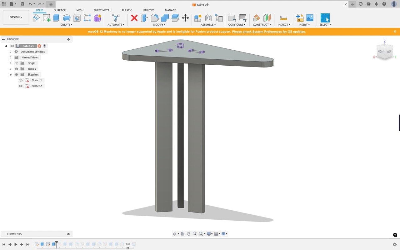
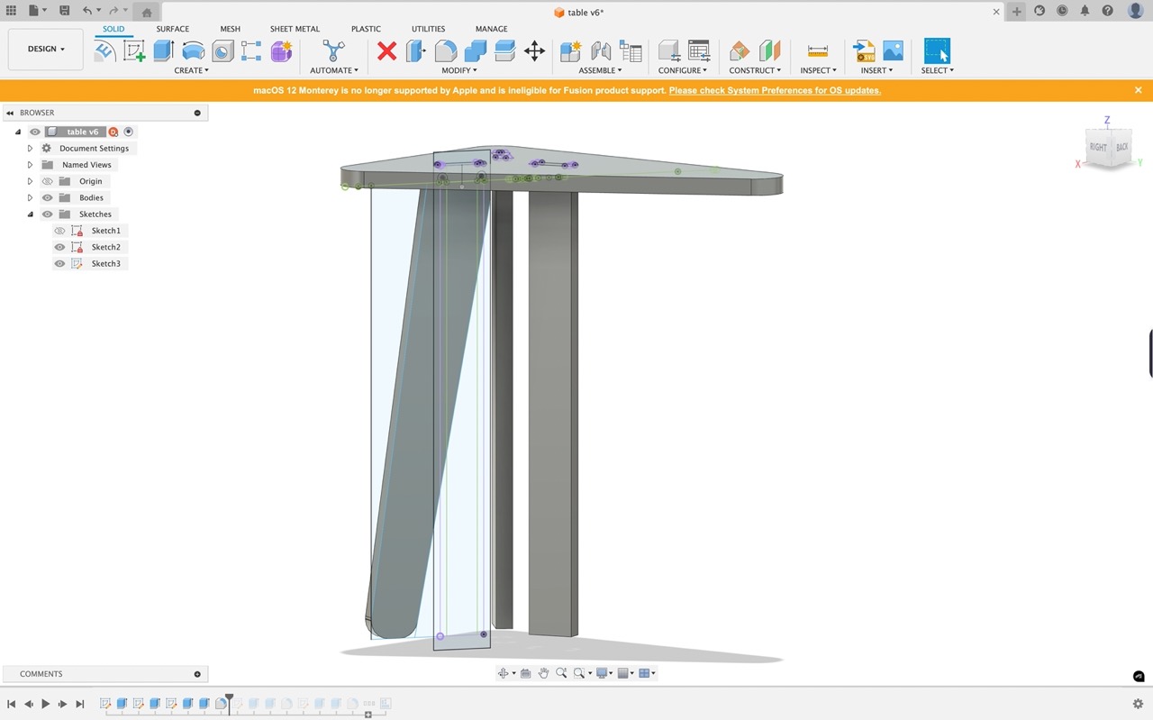
I then extrude the legs from the same sketch (you might need to switch visibility on again in the browser) extrude in two directions. One direction is up to the table top the other will be the height of the table (to the bottom of the table top)
We now have 3 legs make sure you select new body at the bottom of the extrude dialogue or else they will join to the table top
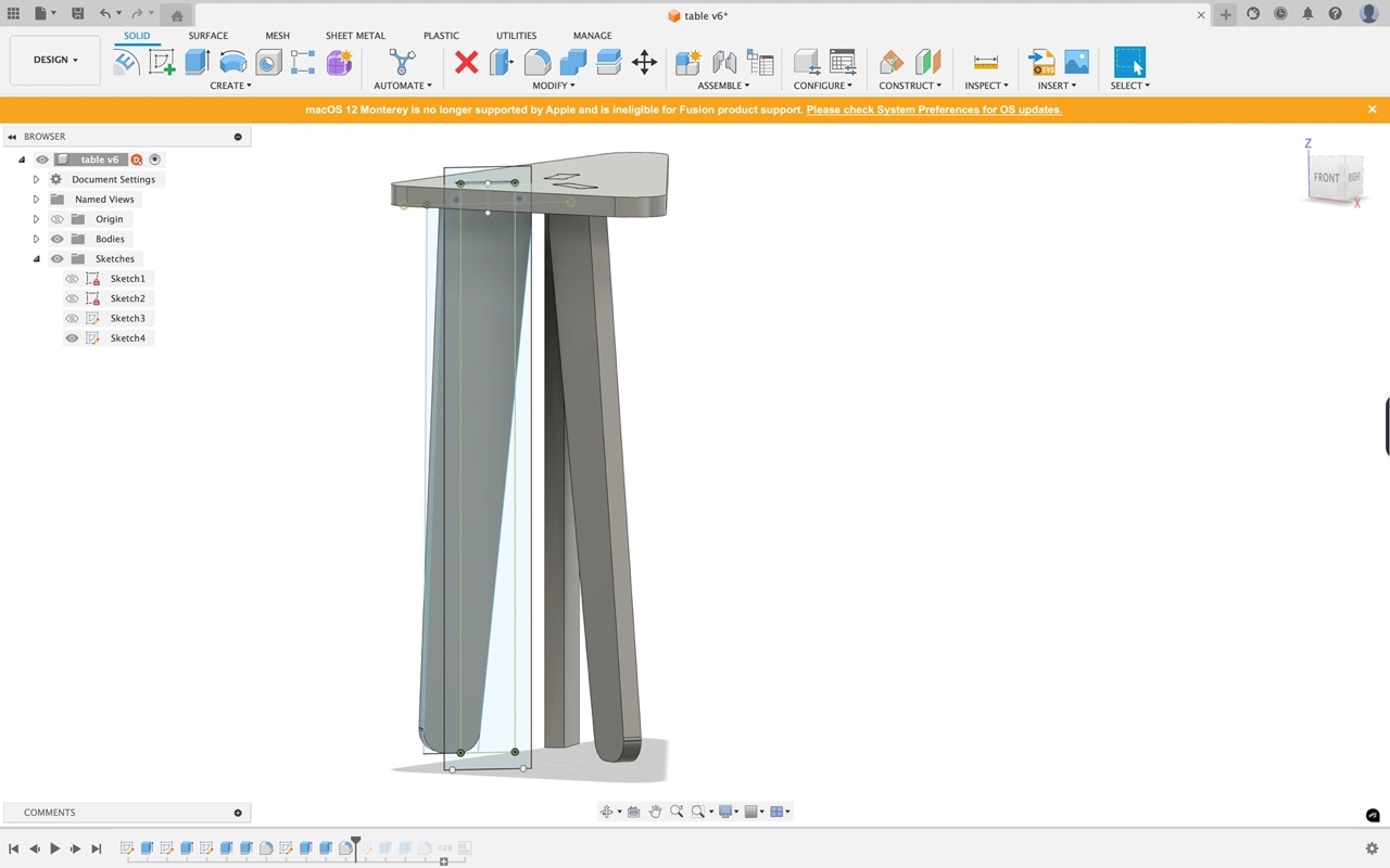
I then created a sketch on the face of one of the legs - this is to create a wider leg than what we currently have as this would be too unstable. I draw a rectangle in the area I want the leg to be and then create two diagonal lines that will make the leg I then need to extrude cut the bit I don't want
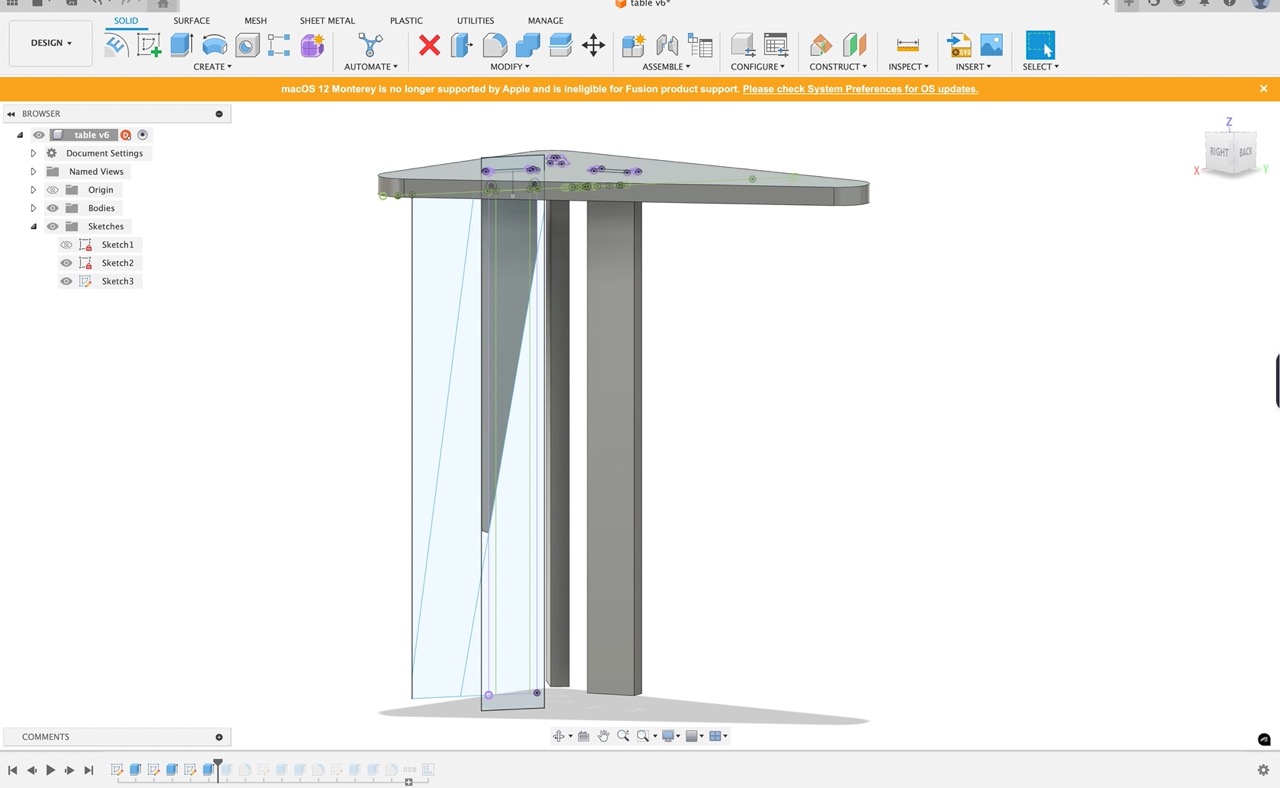
And extrude the bit I do, this time we can join this to the leg body
Add some fillets to round the corners at the bottom of the table legs
Repeat the process for the other legs - we can't circular pattern these as they are all different shapes
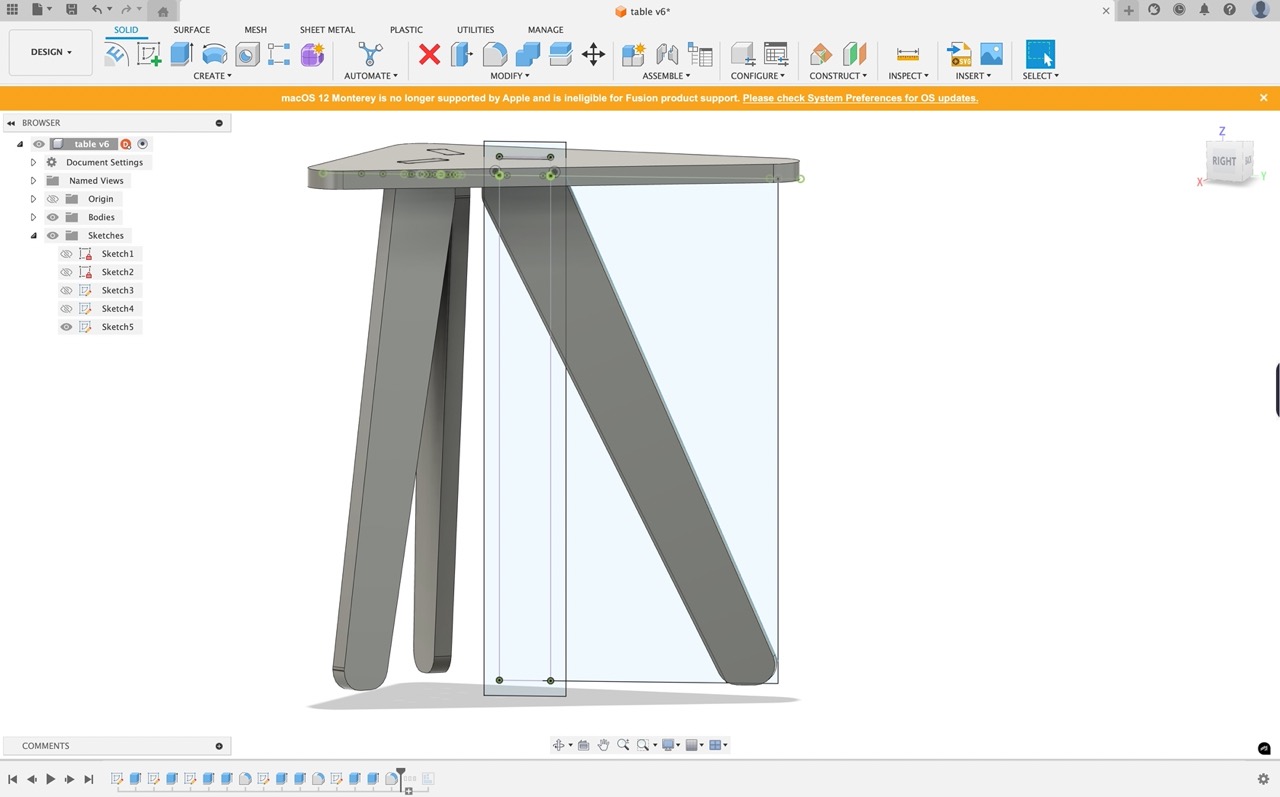
Once all the legs are created we now have to make components from bodies - in the bodies folder in the browser hit the dropdown select all the bodies right click and select create component from bodies. We have to do this to use the arrange feature in the next step.
Then use the arrange tool you can find it under >modify > arrange to lay out the components
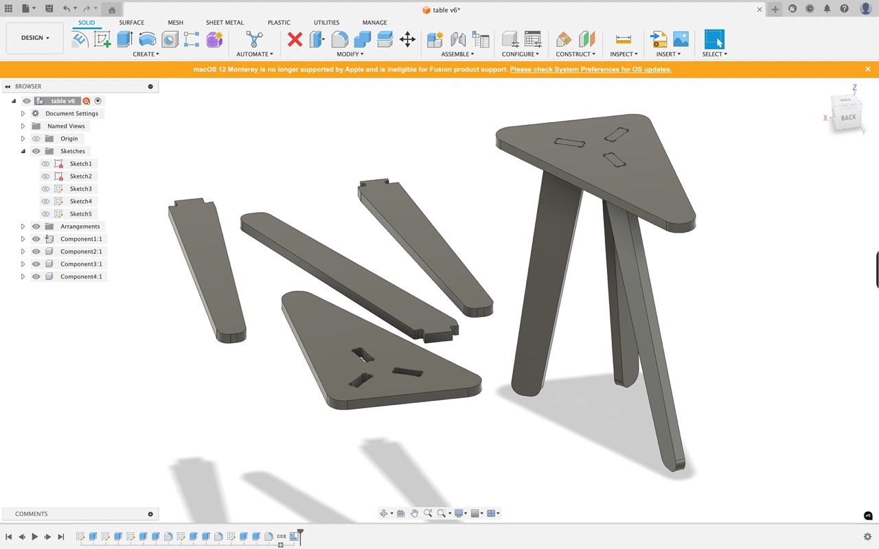
When happy with the layout we can now go to the manufacture workspace to set up the CAM toolpaths..
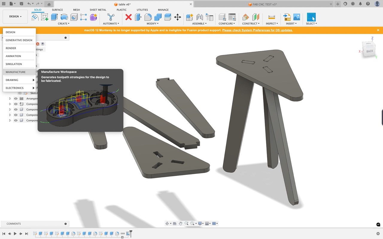
Same procedure as before - create a new setup - select milling as operation type - set up work coordinate system - select the model - set up fixture - select tool - select geometry - set up heights - set up preferences - click OK
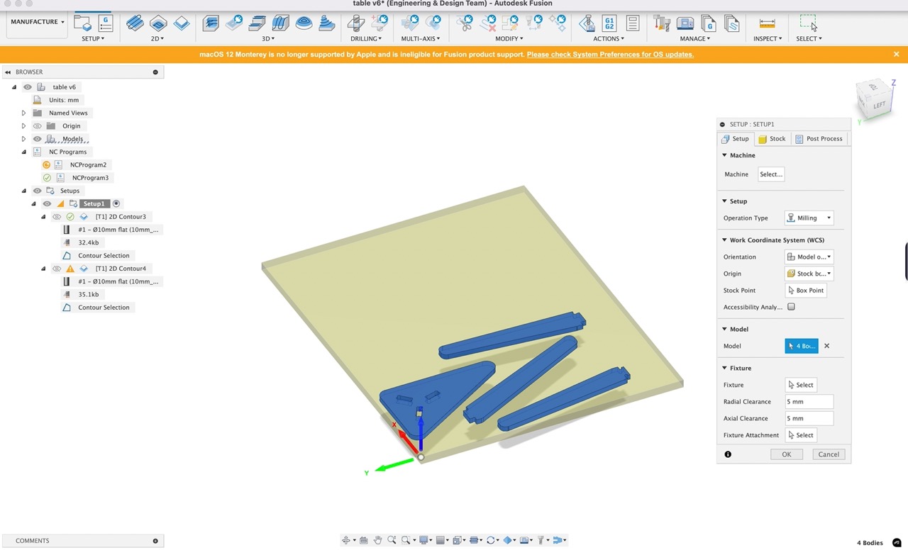
Set the stock size and the appropriate origin location
We can now select 2D contour from the 2D menu bar - select the inner dogbone edges of the part - again choose the 10mm endmill (or whatever tool you plan to use) we can add tabs to the part so it will be held in place in the stock after cutting.
Now we can create a 2D contour toolpath for the outer table top and the legs - select lower outside contour of the table top and the lower face of the legs - again choose the 10mm endmill (or whatever tool you plan to use) we can add tabs to the part so it will be held in place in the stock after cutting.
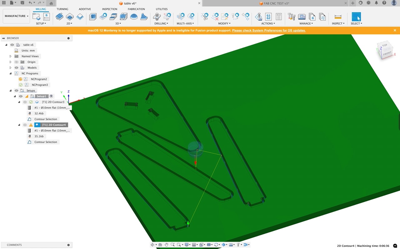
Right click on the generated toolpath and select simulate to see the toolpath in action
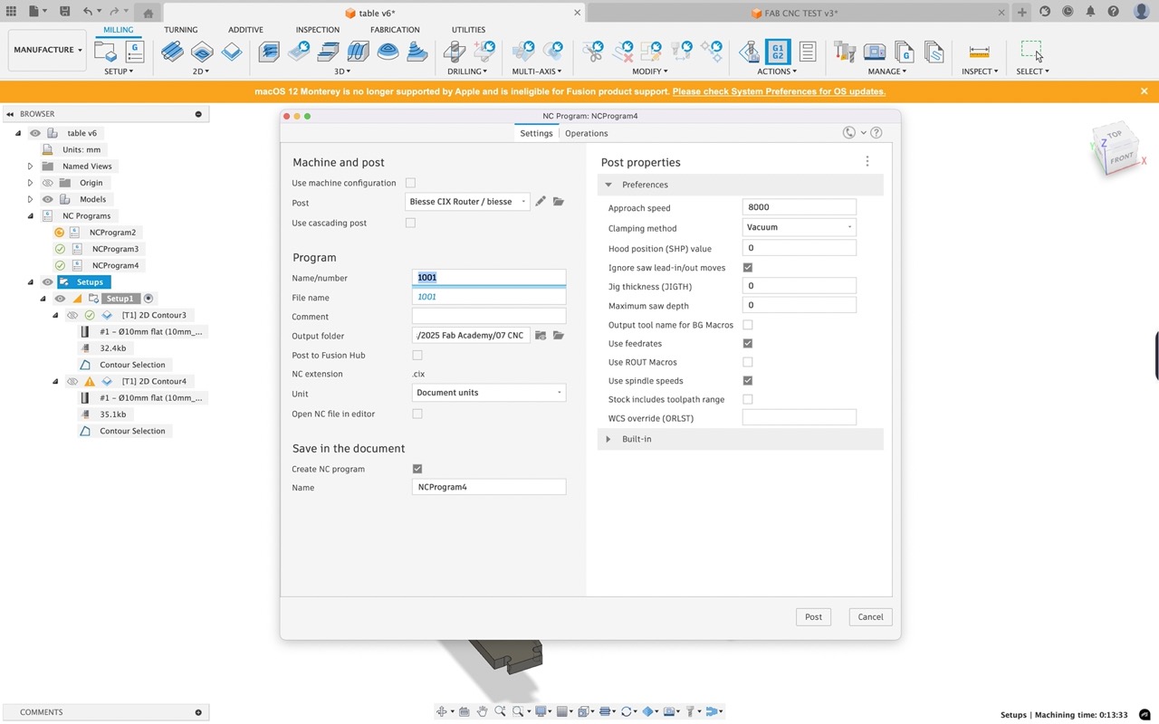
Once complete we can right click on the setup and go to postprocess - a new dialogue window opens - select the machine we will be using - in this case the Biesse Rover. You may need to choose from library and search for your CNC machine.
Post process the part and output the NC file to USB and take it to the CNC machine
Set up the stock on the CNC in my case it is screwed to a spoil board and the screws are well out of the way to the cutting tool paths
Follow the steps described earlier to import the .CXI file into the BSolid
Once in and ready send to the CNC machine by pressing the green button in BSolid
Never leave the CNC unattended as it is cutting
Once complete we just need to remove the tabs and give the edges a light sanding
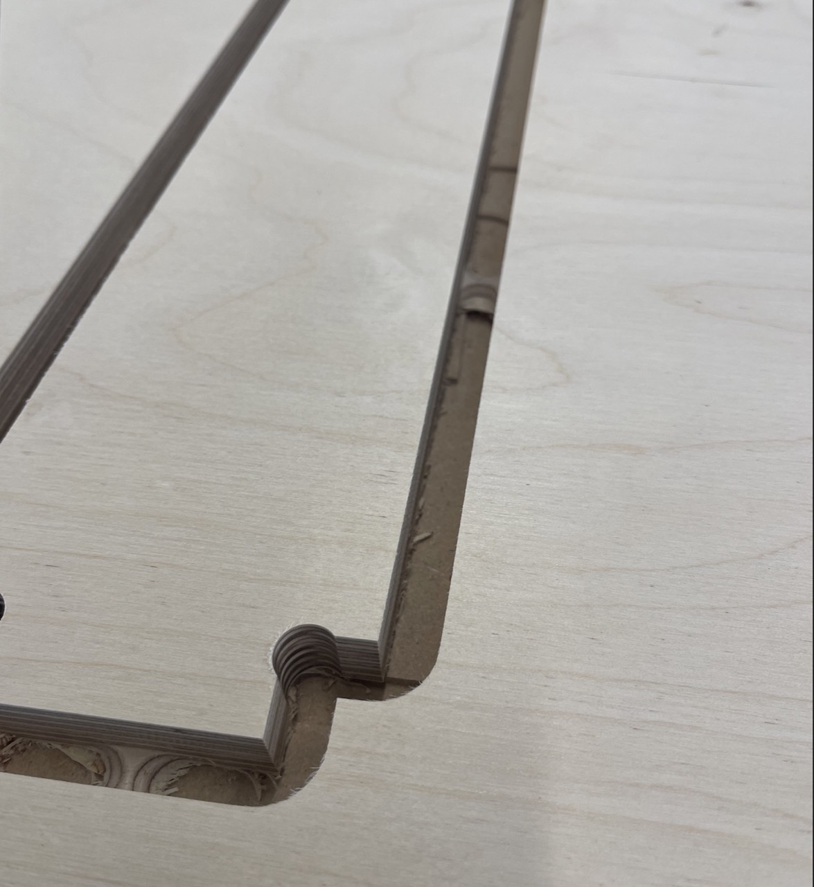
If tolerances were correct we should get good tight fit.
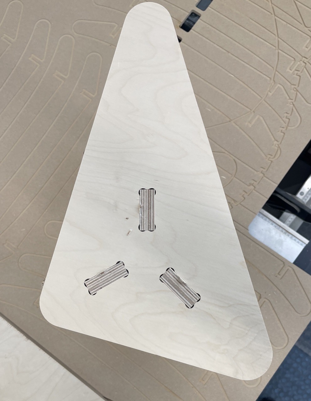
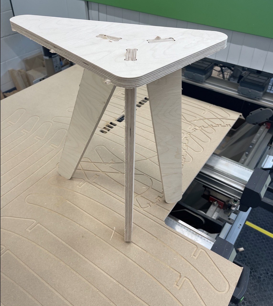
The finished table top and legs assembled.
Issues I've encountered
AGHHHHH
Tool errors in BSolid from the first time sent a programme to the CNC from Fusion - this was due to the tool parameters not being correct in Fusion - they need to match the exact tool parameters in BSolid
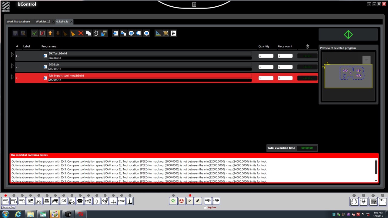
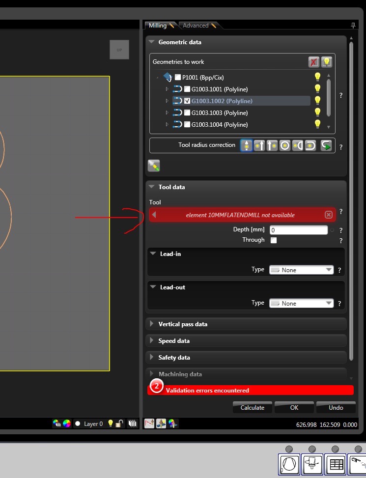
Fixed this in BSolid the first time.
Corrected by correctly setting the tool parameters in Fusion tool Library
Learning Outcomes
This week's key learning outcomes:
- Successfully operated the Biesse Rover CNC machine, including safety procedures, machine setup, and material handling
- Mastered the workflow from Autodesk Fusion 360 to CNC machine, including:
- Creating and simulating toolpaths
- Setting up appropriate cutting parameters
- Post-processing for machine compatibility
- Learned practical design considerations for CNC machining:
- Implementing dogbone joints for square corners
- Using tabs for part stability during cutting
- Designing for assembly without fasteners or glue
- Developed troubleshooting skills for common CNC issues, particularly around tool parameters and machine compatibility
Useful resources discovered: Dogbone plugin Nifty Dogbone plugin