Week 11. Embedded Networking and Communications
Getting social with other boards... let's talk!!
Assignment
Group assignment: (link)
Send a message between two projects
Document your work to the group work page and reflect on your individual page what you learned
Individual assignment:
Design, build and connect wired or wireless node(s) with network or bus addresses and a local input and/or output devices
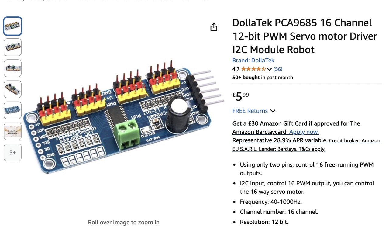
This week I wanted to use the servos using the PCA9685 communicating over I2C and PWM
Would also be communicating with the BNO085 over I2C so this would be a good opportunity to set those up.
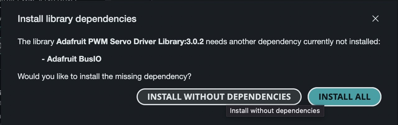
I started by downloading the Adafruit PWM servo driver library and the BNO085 library
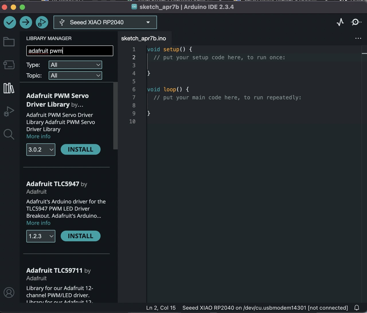
Be sure to install all dependencies
I then opened the sample servo code for the Adafruit servo driver
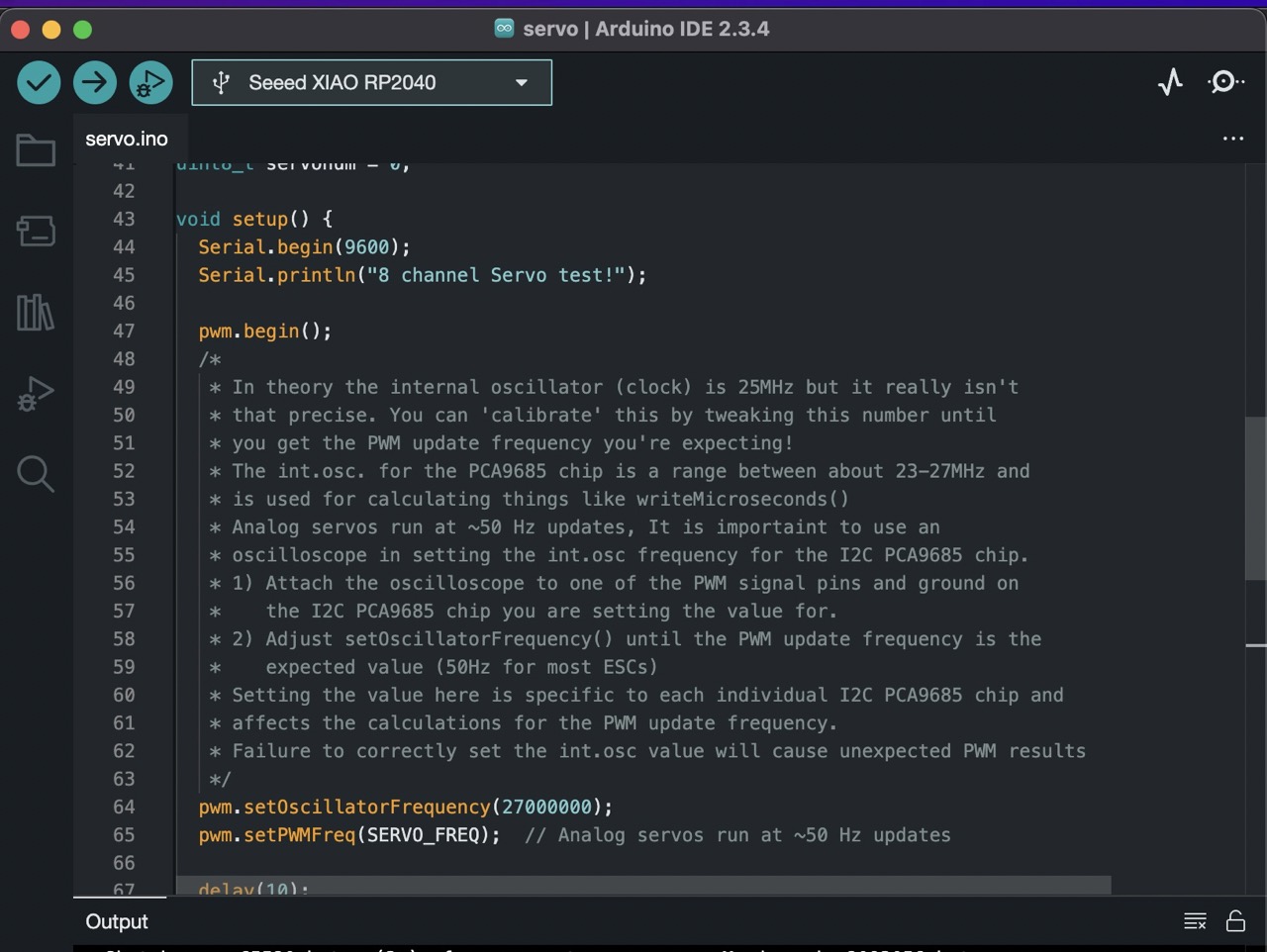
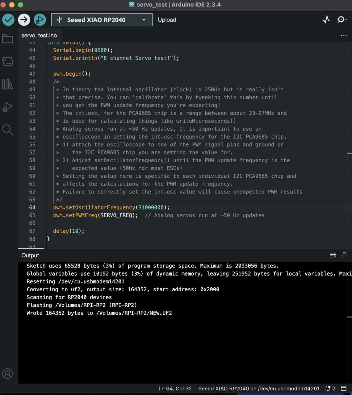
After reading the code description it mentions setting the oscillator frequency so that the board outputs 50Hz
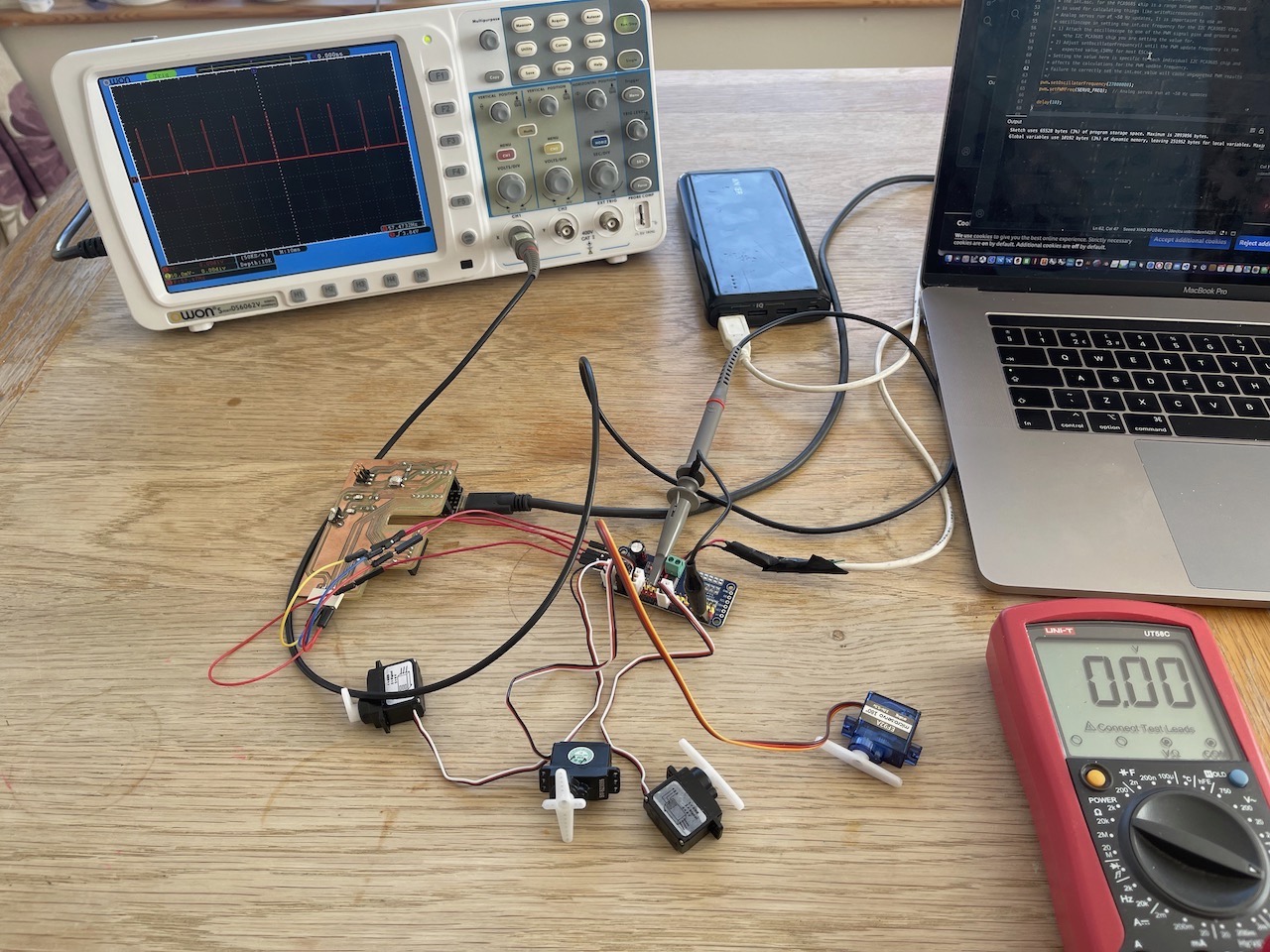
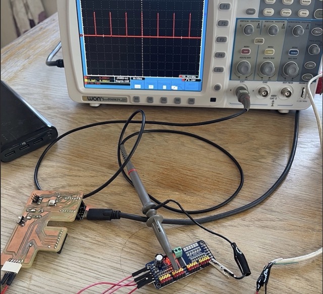
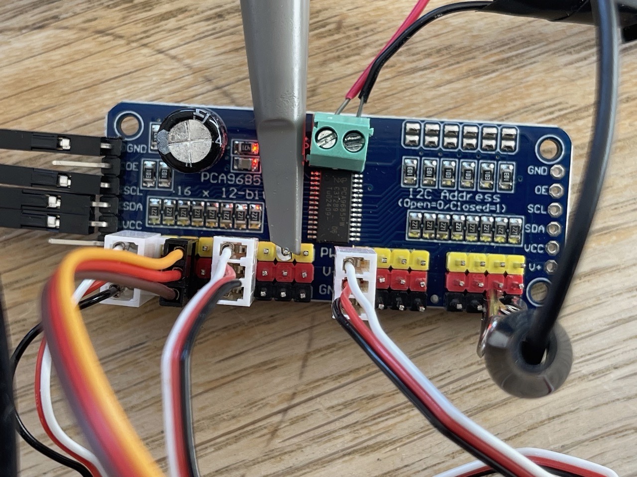
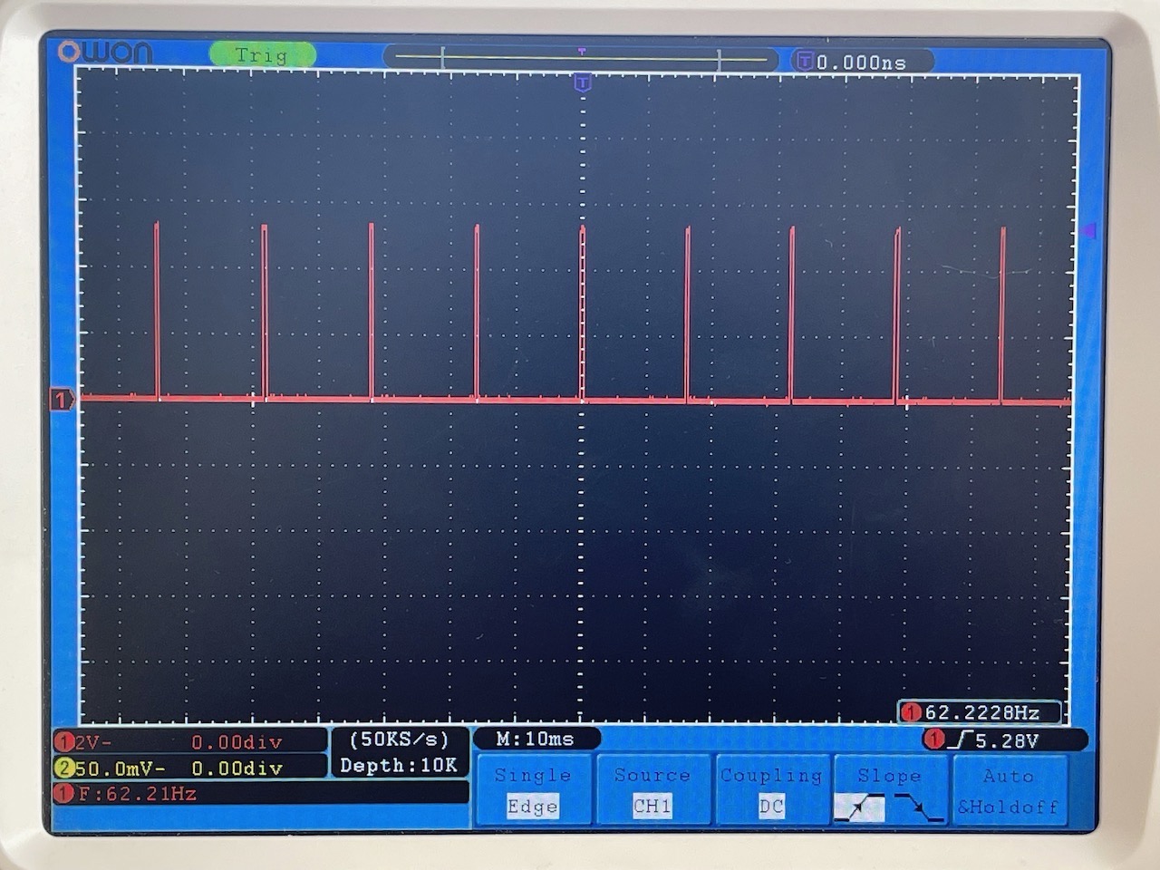
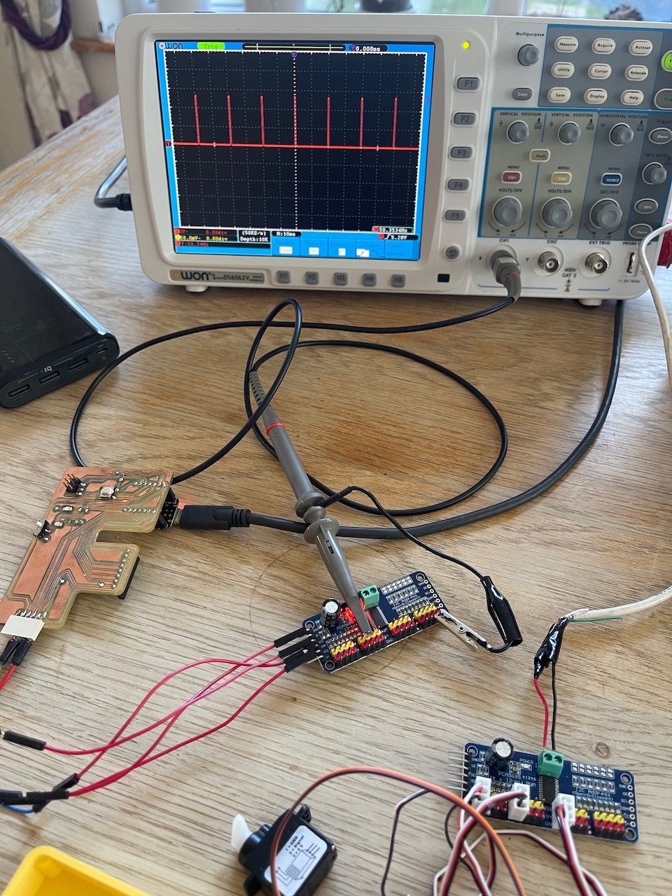
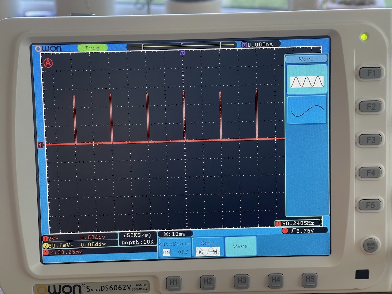
So I got the oscilloscope out to measure the frequency from one of the data pins on the PCA9685
Each board's oscillator frequency will need to be set to get 50Hz reading from the servo pins
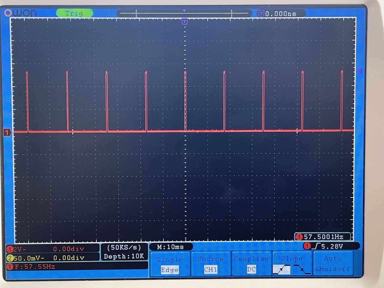
When first connected the reading I got was 57.5Hz with the oscillator frequency set to 27000000
As this was the maximum rated setting I dropped this to 26000000 to see the result however the reading from the PCA9685 went up to 62.2Hz
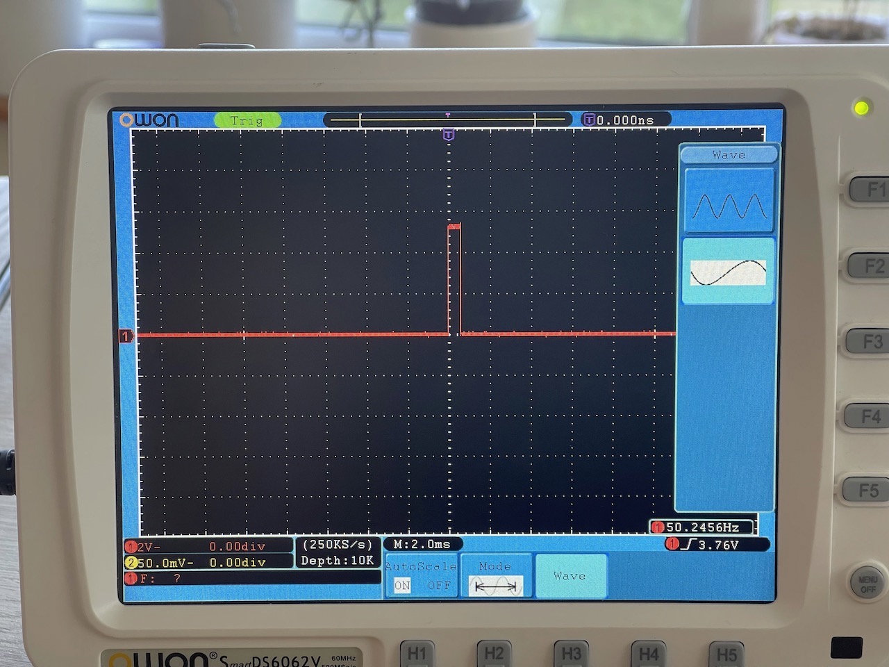
So I increased it up to 31000000 to see if I could get it closer to 50Hz, it was reading 50.27Hz
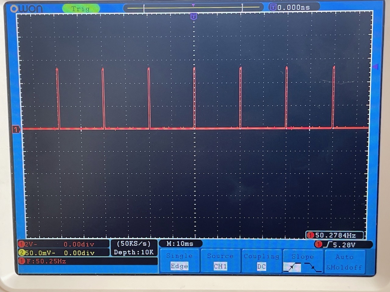
See image below - I'm not sure if it's recommended to set the oscillator to 31000000 as the tech sheet specifies 21000000 - 27000000 but this is what was getting closest to 50Hz with this PCA9685
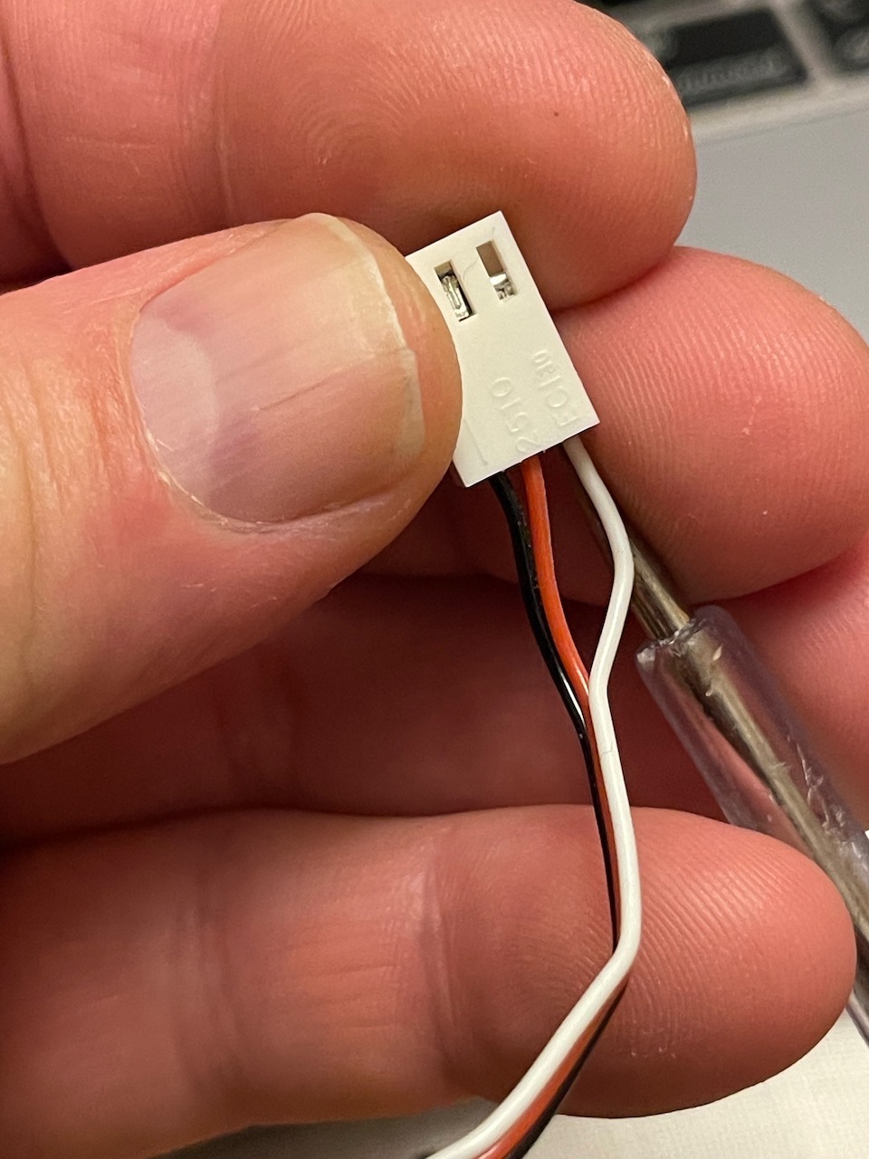
I was using servos I had to hand, they were a mix of low-end servos - however the pins needed to be changed on the connectors as the 5V line was on the outside - for the PCA9685 to work the 5V pins need to be in the middle.
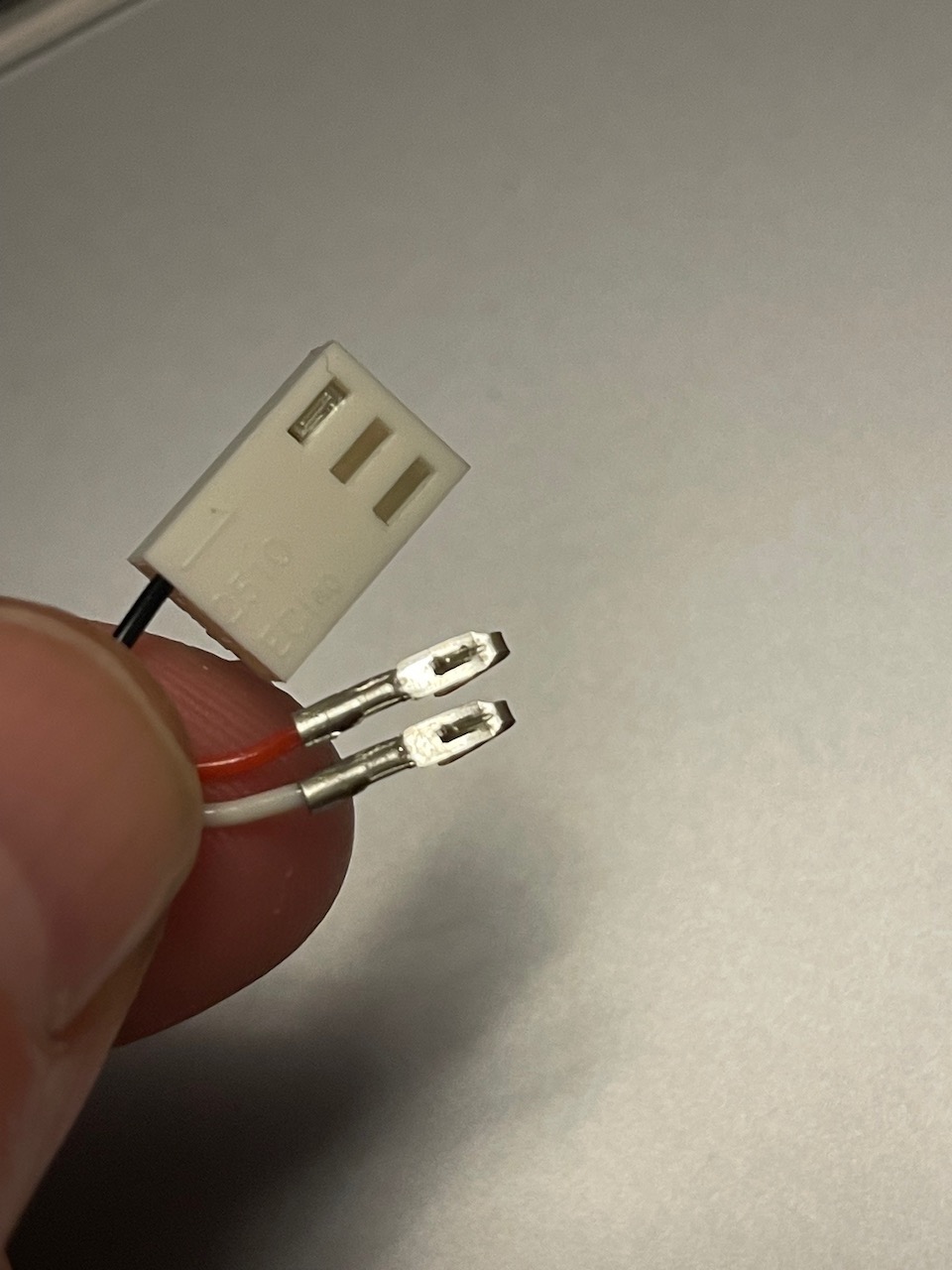
The red and white wires are pulled out by using a fine point to push the retaining clip and pulling the cable out of the connector.

The retaining clip needs to be lifted after pulling it out so they hold when pushed back in.
I was now ready to test the servo code over I2C - I used the sample code from the Adafruit servo driver library
I was using a power bank to power the servos - I had an old USB cable I had used for this, cut the end off and identified the + and - with a multimeter - (this I had done previously)
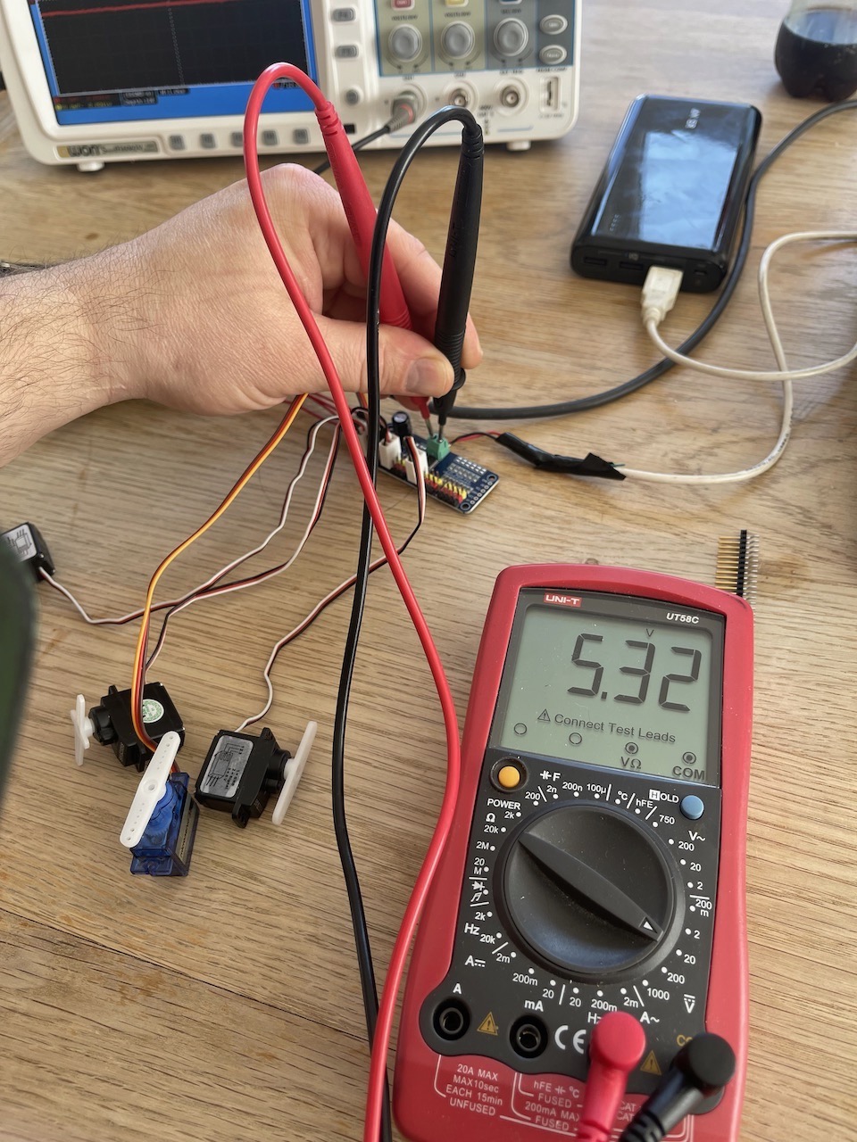
I then connected the power bank to the PCA9685 and the servos to the PCA9685. I checked the power going to the PCA9685 with a multimeter.
I then connected the PCA9685 to the Fab board I had designed with the XIAO RP2040
I then connected the Arduino Nano to the computer and opened the serial monitor to see the servo moving

Below is the sample code I used to test the servo code
/***************************************************
This is an example for our Adafruit 16-channel PWM & Servo driver
Servo test - this will drive 8 servos, one after the other on the
first 8 pins of the PCA9685
Pick one up today in the adafruit shop!
------> http://www.adafruit.com/products/815
These drivers use I2C to communicate, 2 pins are required to
interface.
Adafruit invests time and resources providing this open source code,
please support Adafruit and open-source hardware by purchasing
products from Adafruit!
Written by Limor Fried/Ladyada for Adafruit Industries.
BSD license, all text above must be included in any redistribution
****************************************************/
#include <Wire.h>
#include <Adafruit_PWMServoDriver.h>
// called this way, it uses the default address 0x40
Adafruit_PWMServoDriver pwm = Adafruit_PWMServoDriver();
// you can also call it with a different address you want
//Adafruit_PWMServoDriver pwm = Adafruit_PWMServoDriver(0x41);
// you can also call it with a different address and I2C interface
//Adafruit_PWMServoDriver pwm = Adafruit_PWMServoDriver(0x40, Wire);
// Depending on your servo make, the pulse width min and max may vary, you
// want these to be as small/large as possible without hitting the hard stop
// for max range. You'll have to tweak them as necessary to match the servos you
// have!
#define SERVOMIN 155 // This is the 'minimum' pulse length count (out of 4096)
#define SERVOMAX 595 // This is the 'maximum' pulse length count (out of 4096)
#define USMIN 600 // This is the rounded 'minimum' microsecond length based on the minimum pulse of 150
#define USMAX 2400 // This is the rounded 'maximum' microsecond length based on the maximum pulse of 600
#define SERVO_FREQ 50 // Analog servos run at ~50 Hz updates
// our servo # counter
uint8_t servonum = 0;
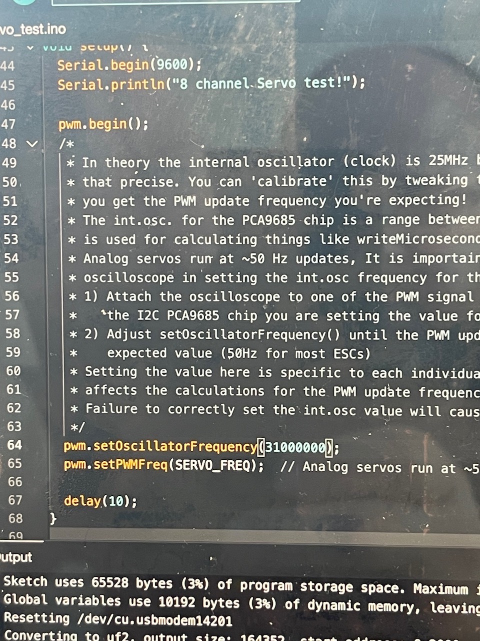
void setup() {
Serial.begin(9600);
Serial.println("8 channel Servo test!");
pwm.begin();
/*
* In theory the internal oscillator (clock) is 25MHz but it really isn't
* that precise. You can 'calibrate' this by tweaking this number until
* you get the PWM update frequency you're expecting!
* The int.osc. for the PCA9685 chip is a range between about 23-27MHz and
* is used for calculating things like writeMicroseconds()
* Analog servos run at ~50 Hz updates, It is importaint to use an
* oscilloscope in setting the int.osc frequency for the I2C PCA9685 chip.
* 1) Attach the oscilloscope to one of the PWM signal pins and ground on
* the I2C PCA9685 chip you are setting the value for.
* 2) Adjust setOscillatorFrequency() until the PWM update frequency is the
* expected value (50Hz for most ESCs)
* Setting the value here is specific to each individual I2C PCA9685 chip and
* affects the calculations for the PWM update frequency.
* Failure to correctly set the int.osc value will cause unexpected PWM results
*/
pwm.setOscillatorFrequency(31000000);
pwm.setPWMFreq(SERVO_FREQ); // Analog servos run at ~50 Hz updates
delay(10);
}
// You can use this function if you'd like to set the pulse length in seconds
// e.g. setServoPulse(0, 0.001) is a ~1 millisecond pulse width. It's not precise!
void setServoPulse(uint8_t n, double pulse) {
double pulselength;
pulselength = 1000000; // 1,000,000 us per second
pulselength /= SERVO_FREQ; // Analog servos run at ~60 Hz updates
Serial.print(pulselength); Serial.println(" us per period");
pulselength /= 4096; // 12 bits of resolution
Serial.print(pulselength); Serial.println(" us per bit");
pulse *= 1000000; // convert input seconds to us
pulse /= pulselength;
Serial.println(pulse);
pwm.setPWM(n, 0, pulse);
}
void loop() {
// Drive each servo one at a time using setPWM()
Serial.println(servonum);
for (uint16_t pulselen = SERVOMIN; pulselen < SERVOMAX; pulselen++) {
pwm.setPWM(servonum, 0, pulselen);
}
delay(500);
for (uint16_t pulselen = SERVOMAX; pulselen > SERVOMIN; pulselen--) {
pwm.setPWM(servonum, 0, pulselen);
}
delay(500);
// Drive each servo one at a time using writeMicroseconds(), it's not precise due to calculation rounding!
// The writeMicroseconds() function is used to mimic the Arduino Servo library writeMicroseconds() behavior.
for (uint16_t microsec = USMIN; microsec < USMAX; microsec++) {
pwm.writeMicroseconds(servonum, microsec);
}
delay(500);
for (uint16_t microsec = USMAX; microsec > USMIN; microsec--) {
pwm.writeMicroseconds(servonum, microsec);
}
delay(500);
servonum++;
if (servonum > 7) servonum = 0; // Testing the 16 servo channels
}
Networking between 2 boards
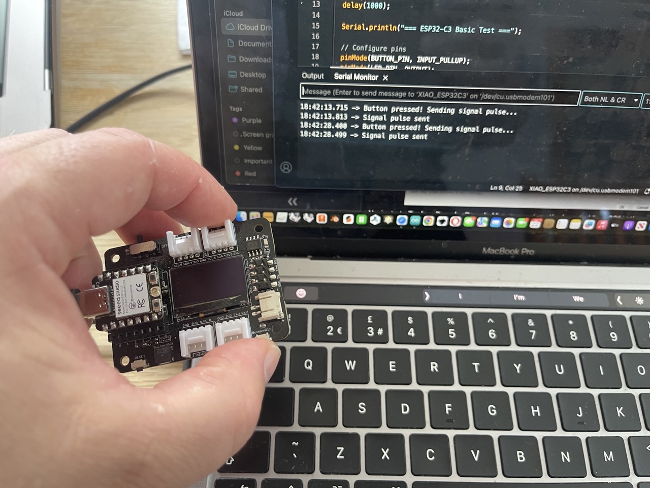
This project demonstrates direct wire communication between two XIAO boards:
- XIAO ESP32-C3 (on Seeed Studio Expansion Board V1.1) - sends signals via A0/D0 pin
- XIAO RP2040 (on custom breakout board) - receives signals via pin 8
Hardware Setup
- ESP32-C3: Connected to Seeed Studio Expansion Board V1.1 with built-in button
- RP2040: Connected to custom breakout board with external LED
- Direct Connection: Wire from ESP32-C3 A0/D0 pin to RP2040 pin 8
Communication Flow
- ESP32-C3 monitors button press on expansion board
- When button is pressed, ESP32-C3 sends HIGH signal via A0/D0 pin
- RP2040 receives signal on pin 8 and turns on LED
- After 2 seconds, RP2040 turns LED off and sends acknowledgment signal back
Files
esp32c3_sender/- Code for XIAO ESP32-C3 (signal sender)rp2040_receiver/- Code for XIAO RP2040 (signal receiver)wiring_diagram.md- Hardware connectionstest_script.ino- Basic functionality test
Requirements
- Arduino IDE with ESP32 and RP2040 board support
- Direct wire connection between boards
- Basic understanding of digital I/O communication
Setup Instructions
- Upload
esp32c3_sender.inoto your XIAO ESP32-C3 - Upload
rp2040_receiver.inoto your XIAO RP2040 - Connect wire from ESP32-C3 A0/D0 to RP2040 pin 8
- Press button on expansion board to test communication
I leveraged Cursor AI to create the Code for this project - the code and prompts are avalaible in the download section below.
See images below. I was using the test code created for the two boards to check they were working individually.

Notice anything wrong with the image below - yep, no ground cable - it's very important - that only took about 20 min of troubleshooting


And after connecting the ground cable we are in business!!
The code and Cursor AI conversation to create the code is in the digital files download below
Issues I've encountered
AGHHHHH!
What went wrong.
ESP32-C3 would not compile in Arduino IDE - I was using an alpha version - so in board manager I searched ESP32, uninstalled what was there and selected a non-alpha version, in my case 3.2.0
Not connecting the ground pin to the two boards when sending a signal.
I'm not sure what the cause of setting the oscillator clock to 31MHz will be in the long run or how accurate the 50Hz reading needs to be - but it seems to be working for this initial test
The servo connectors did not fit beside each other on the PCA9685 board - so I had to place them where they would fit on the board
Learning Outcomes
Demonstrate workflows used in network design
Implement and interpret networking protocols and/or communication protocols