Final Project
My final project idea is to build a hexapod or Stewart platform.

Hexapod / Stewart Platform
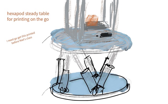
Develop a hexapod platform, starting with a small-scale version using servos, with the long-term goal of creating a larger-scale version with the function of holding a 3D printer steady when on the move.
The intention is to keep it stable when travelling on the road (see video highlighting a section of the journey to the FabLab).
Use Cases
Driving or Flight Simulator Rig.
Building a low-profile rig that could sit under an existing stationary sim rig would be interesting.
Challenges for this would be platform weight requirements.
Tapping into the driving or flight sim to get feedback on where the hexapod should be – bumps, g-force simulation etc.
Multi-axis 3D Print Platform.
Modify an existing printer to add multi-axis print capability such as delta WASP printer or an Ultimaker-type printer – I don't think it would work well on a bed slinger.
Steady Bench/Table.
The intention with this is to put the 3D printer in the back of the mobile technology van to have the capability to print on the road – I want to be able to keep the printer steady while on the move.
I need to get my model printed for Fab Academy – as usual, last-minute CAD modelling – 1:30 hr print – 1:30 hours' drive to the FabLab – going to have to print and drive.
Considerations
Size of hexapod – let's aim to hold an Ultimaker 2+ (can also test with Prusa i3 Mk3)
Speed requirement of linear actuator and load capability. (Will I build the linear actuators with stepper motors or get off-the-shelf parts? Further research required – I have stepper motors from 4-5 Makerbot Replicator 2 printers that I could cannibalise for parts)
Spiral Development
Sketch of the idea –
CAD model –
Small-scale servo model –
Specify the linear actuator requirements
Design larger-scale platform –
Build table in back of the van to hold the part.
Start with the sketch
and move on to a servo model that we can use to test code and the principle on a small scale.
Then scale up to larger platform.
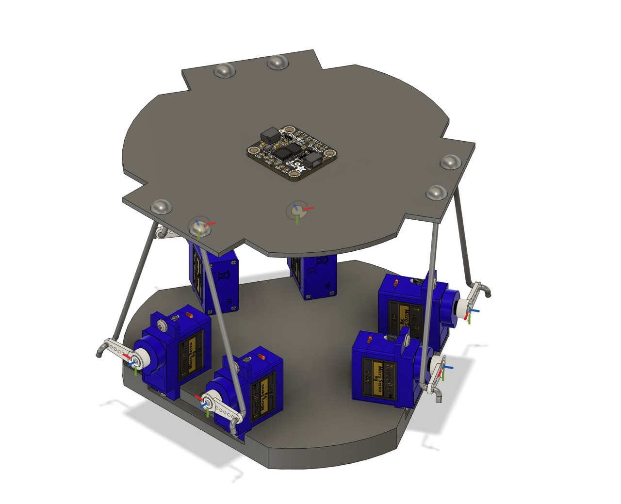
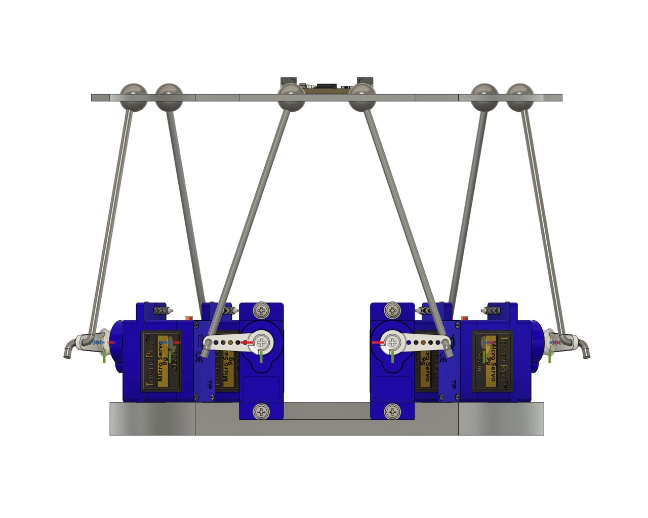
Initial CAD Model Using Rhino and Grasshopper
Existing Hexapod Development
I found some links to existing works – I need to identify which of these I can use as the basis for this project.
NicHub Stewart-Platform-Esp32 GitHub
Video and GitHub link for motion tracking hexapod code in Python
Yeok-c Stewart_Py YouTube
Yeok-c Stewart_Py GitHub
Week 3 Final Project Research
Useful links this week.
Complete Guide to PCA9685 16 Channel Servo Controller for Arduino with Code Version 5 (V1)
Week 4 Final Project Research
Not much progress on the Final Project this week...
Week 5 Final Project Research
In the interest of spiral development, I'll be making a small servo version first - I've looked at the various projects out there and will be basing my initial design on Yeok-c's Stewart platform simulator. However, I hope to make some additions and will not be using his motion capture. Link to Git repo below.
Yeok-c Stewart_Platform Motion Simulator GitHub
I've also found a few other links that may be useful for the project.
Week 6 Final Project Research
I've been working on the servo version of the hexapod this week.
Week 7 Final Project Research
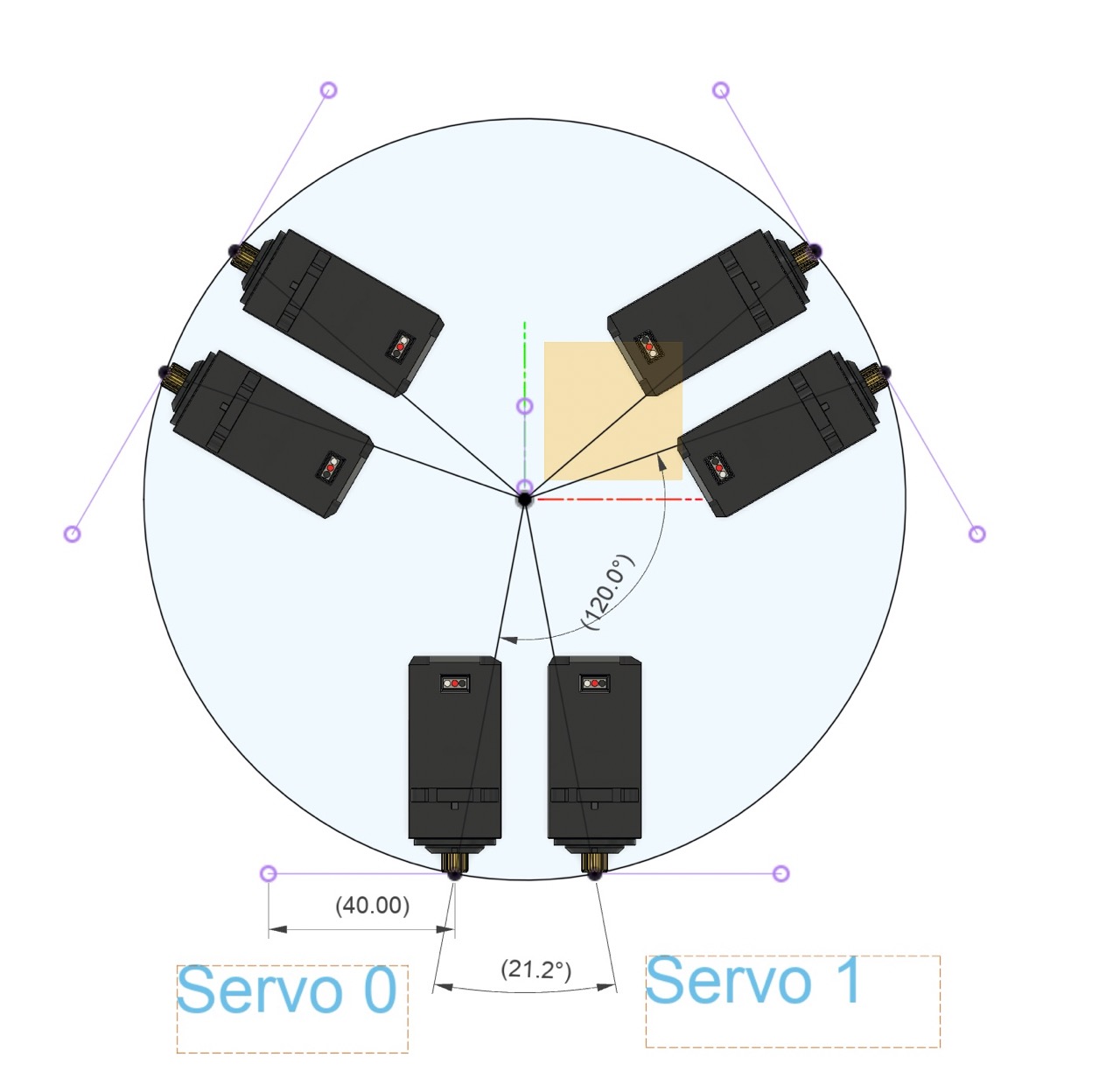
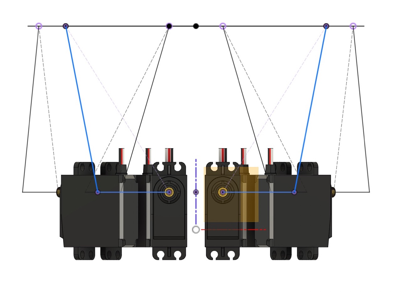
I've been reading up about inverse kinematics and how to calculate the angles of the servos to move the hexapod. Credit to Yeok-c Stewart_Platform Motion Simulator

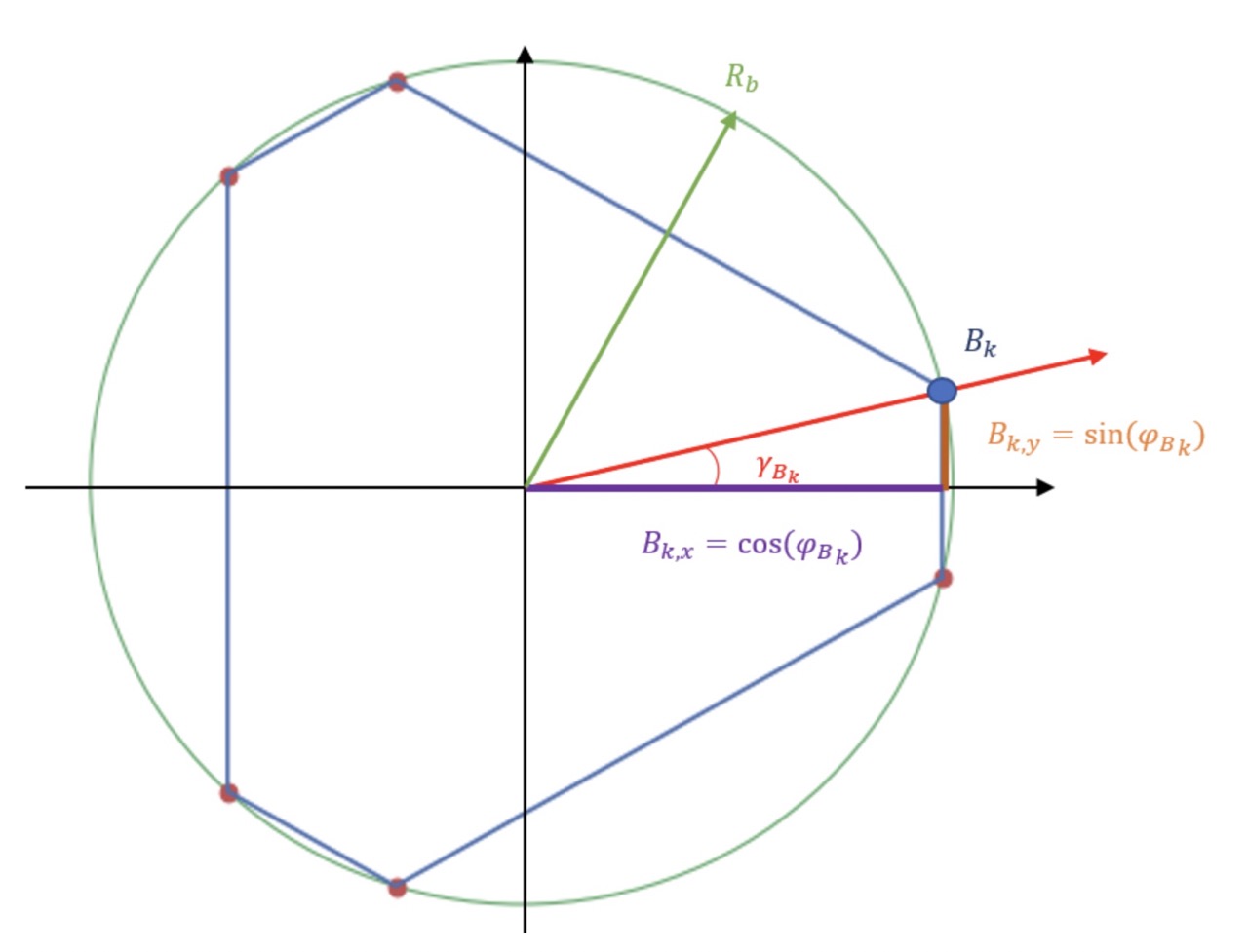
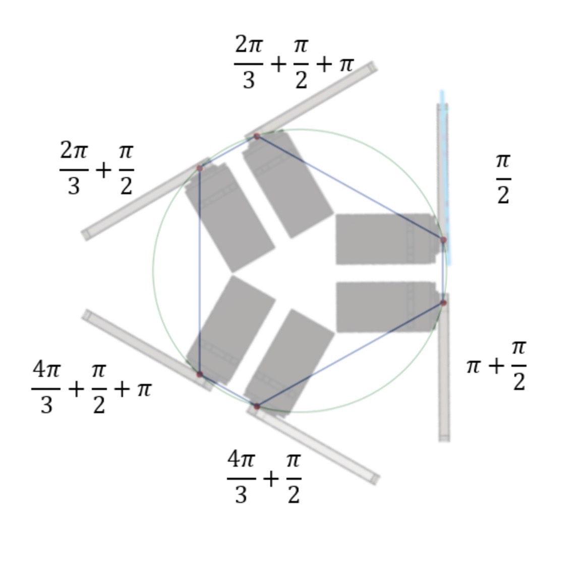
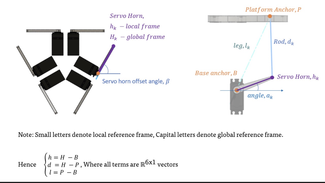
The above images and geometry sketch are from Yeok-c's Stewart platform motion simulator - I'm using this as a base for my own design. My platform dimensions will change from Yeok-c's design to suit my own needs.
The images can be found in Yeok-c's GitHub repo Yeok-c Stewart_Platform Motion Simulator GitHub
Week 8 Final Project Research
I've been working on the servo version of the hexapod this week.
Week 9 Final Project Research
Been working on the CAD design of the small hexapod.
Week 10 Final Project Research
Found this link this week: Dynamical Stabilisation of a Plane Using a Gough-Stewart Platform
Week 11 Final Project Research
So my question this week after the networking session is: should I use stepper motors for the full-size version and have a controller for each stepper controlled with an ATtiny412?
If that was the case, each linear actuator would have its own controller that would then communicate to a central processor - this might not be feasible - just me thinking out loud.
Week 12 Final Project Research
I've been working on the CAD design to incorporate full-size servos in the final project.
- Mid-term Review - April 16th 2025 -
List the tasks to be completed, make a schedule for doing them, meet with your local and global instructors to review these and your weekly assignments.
See Gantt chart below outlining tasks to be completed and a schedule for doing them

Week 13 Final Project Research
Specify the power supply for the hexapod - I leveraged ChatGPT to help me with this. Chat with prompts below -
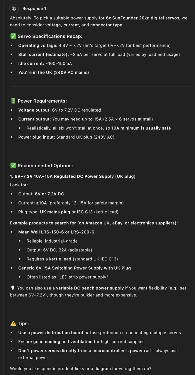
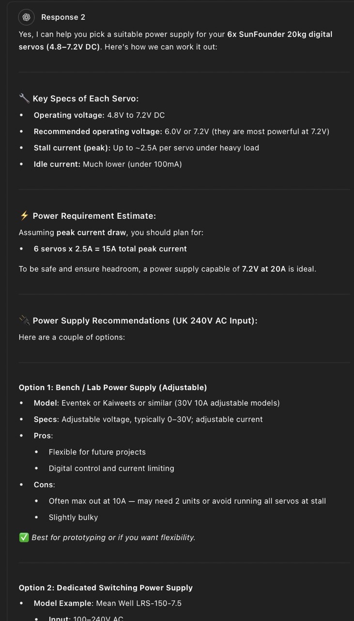
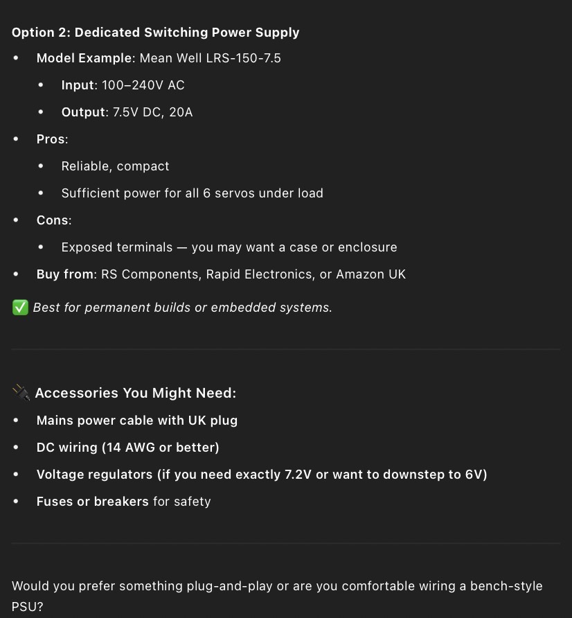
The chat led me to the Mean Well RSP-150-7-5 power supply - I'm going to use this for the hexapod to power the servos
Spiral development - I'm going to use the image below to guide my development process.
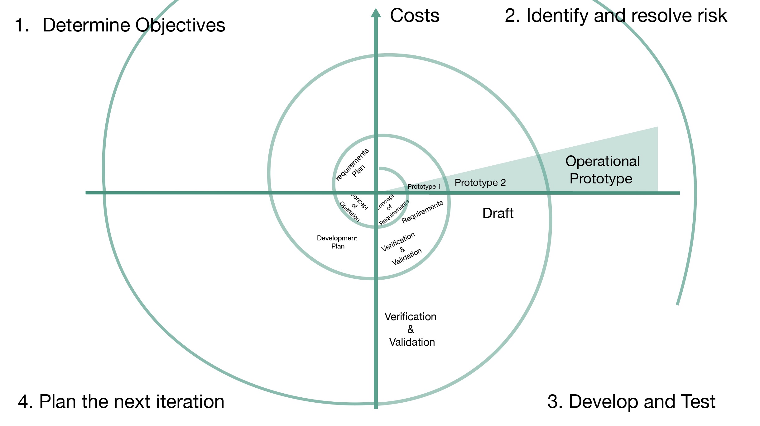
Image based on the spiral model on Wikipedia - see link: https://en.wikipedia.org/wiki/Spiral_model
Week 13 Final Project Research
Prototype parts of the hexapod
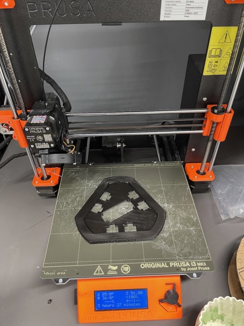
3D print the parts for the base - At this stage I decided to use the full-size servos as I was having issues with the small ones - they were not all the same model and they were only moving approximately 90 degrees. This was documented in output devices week.
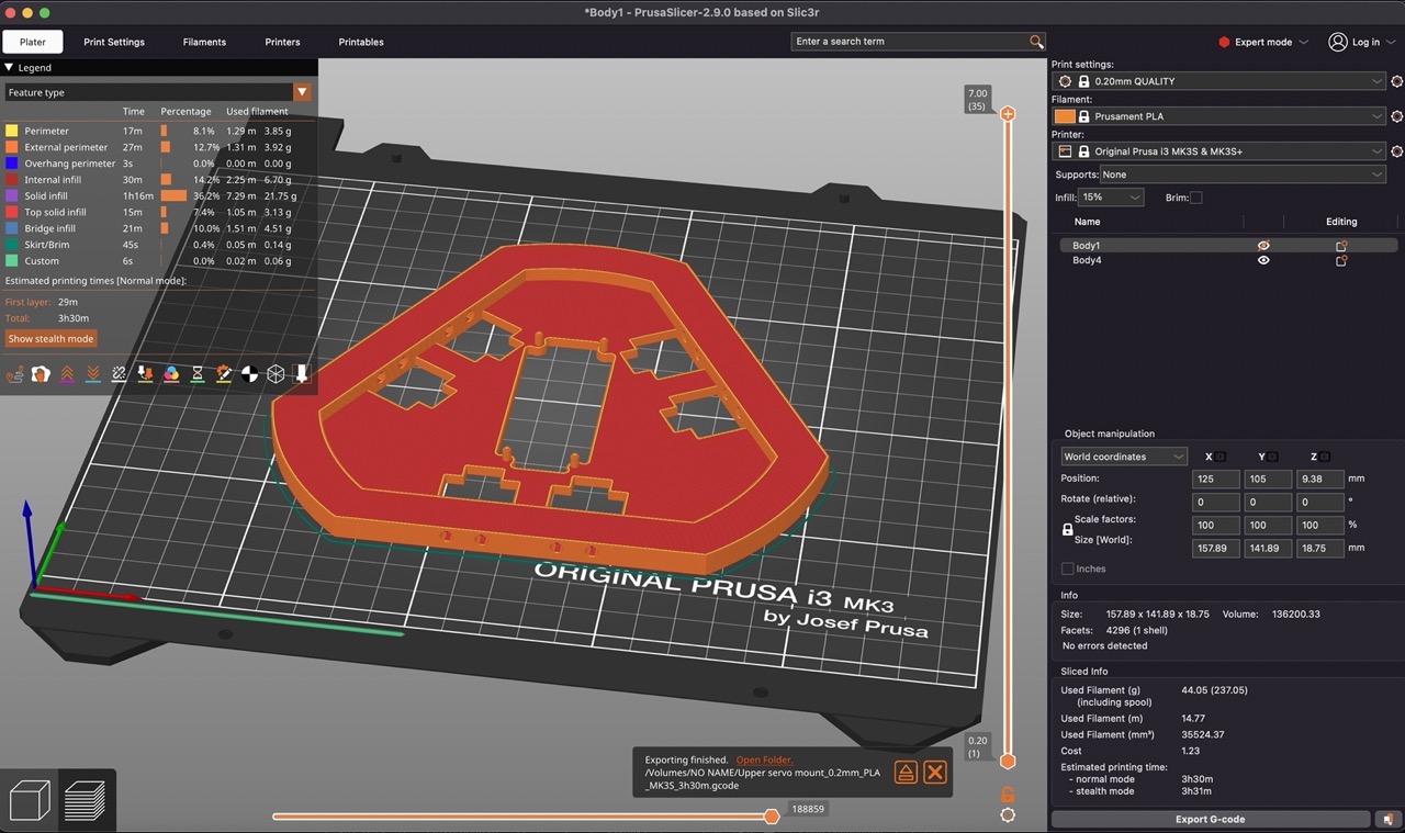
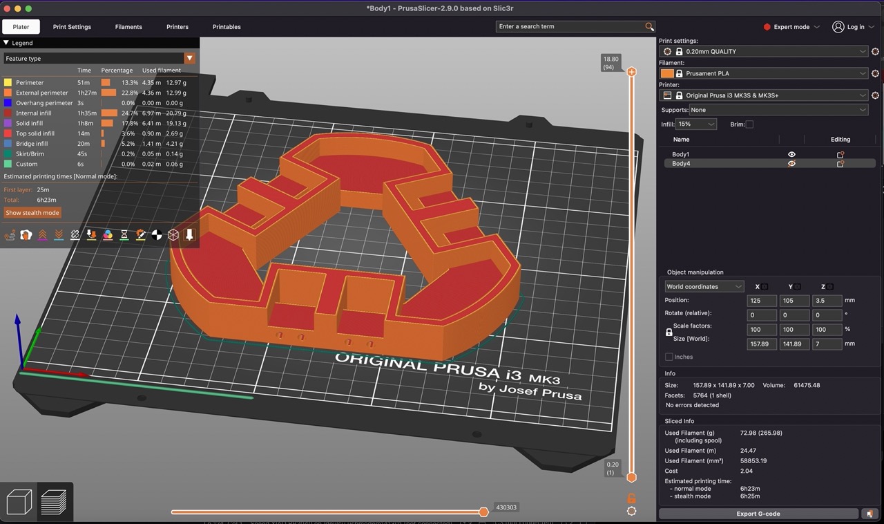
3D print the parts - export or send the parts direct from Autodesk Fusion to Prusa Slicer.
To do that you right-click on the parts to export in Fusion and select save as mesh.
For the dialogue screen you can select the slicing software installed on your computer - if it's not visible you can manually select it by clicking select other.
The files will then send direct to the slicing software.
Below are some screenshots and images of the CAD, sliced file and printed parts on the Prusa i3 MK3
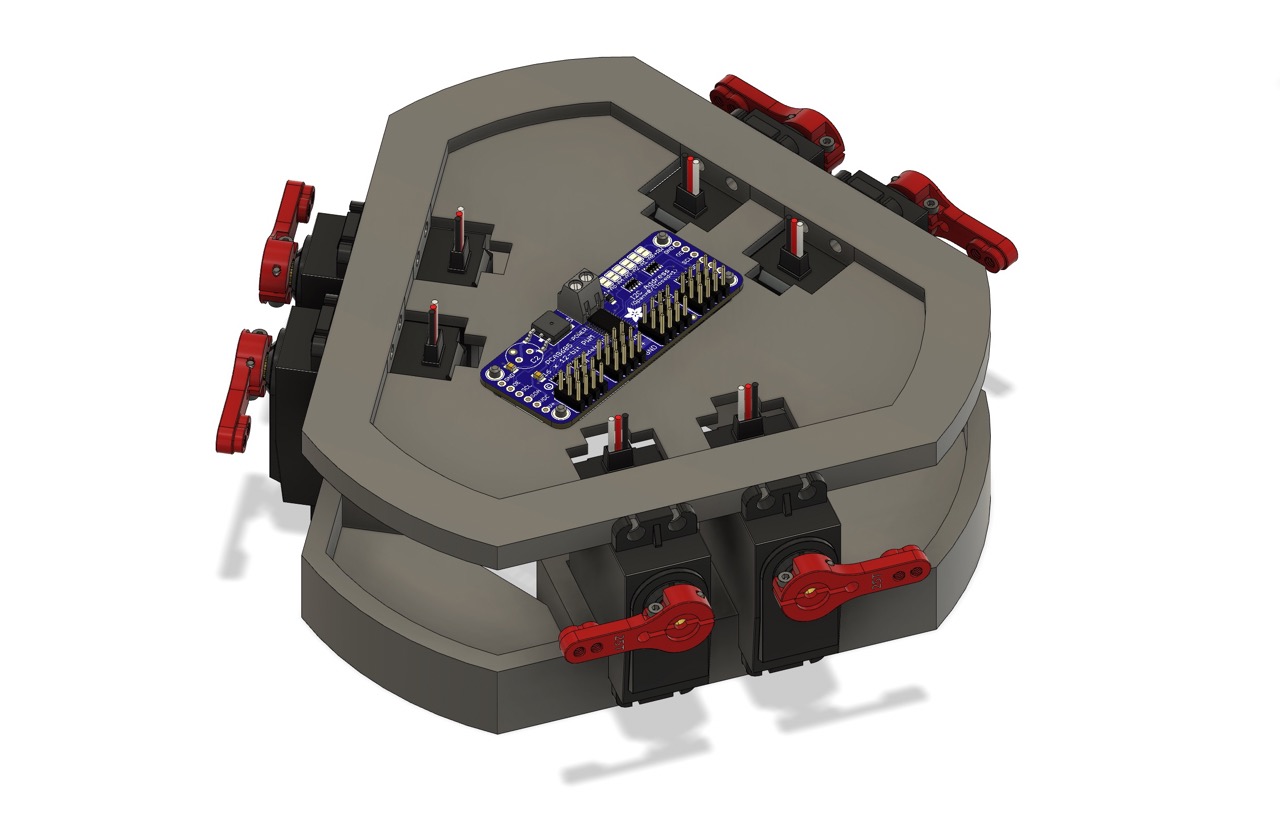
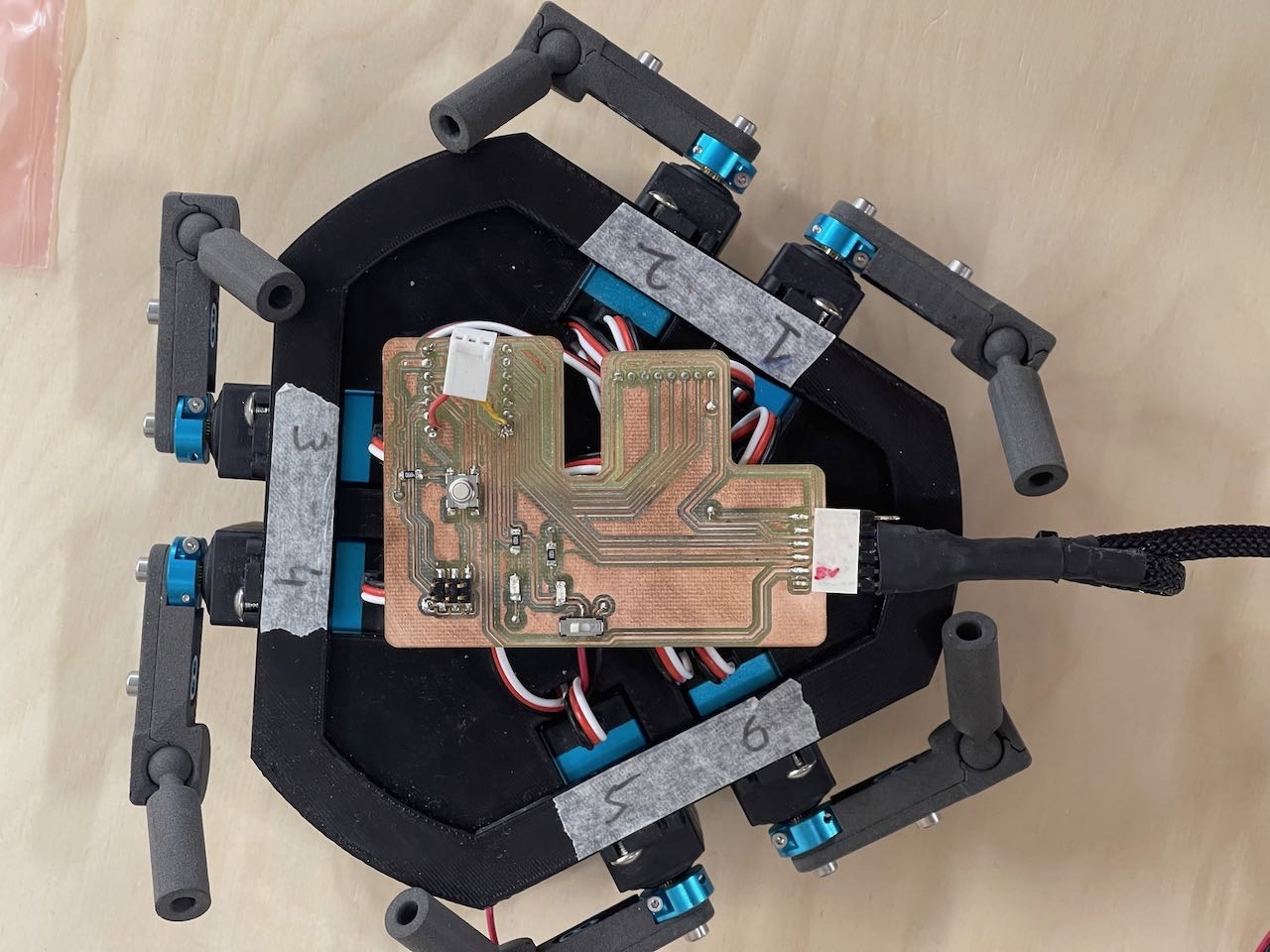
Below I begin the assembly process mounting the servos to the printed parts.
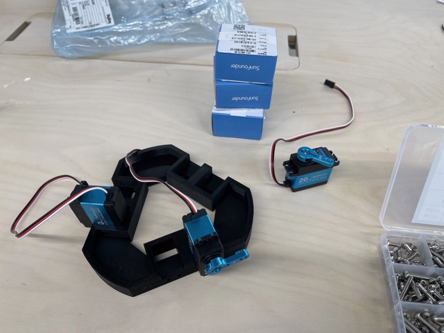
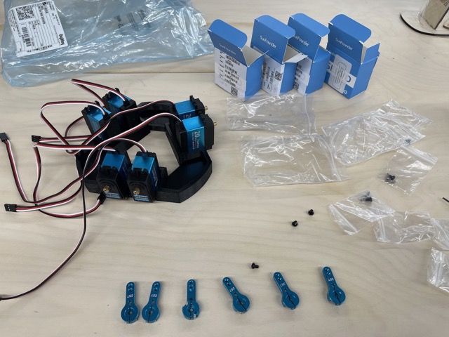
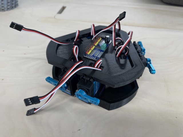
Here is the base and mid plates assembled to the servos and the servo controller board mounted to the mid plate. Things are coming together.
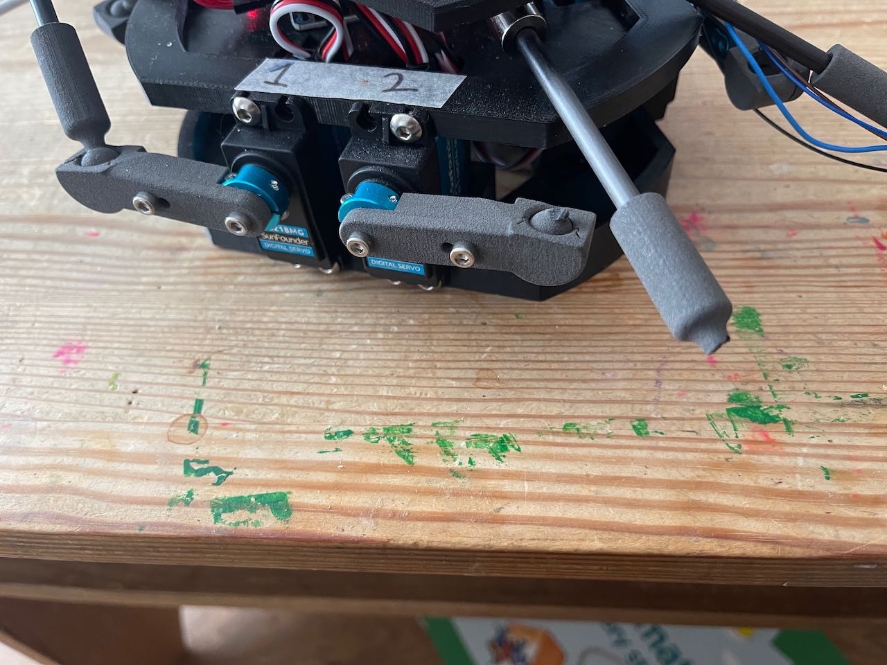
I take the servo arms off the base to prevent damage while I set up the servo code using Arduino IDE

Video below shows testing the servo range of motion - I'm using small marked printed caps so the servo arms won't bump into each other potentially causing damage. These servos are very powerful - watch your fingers!! You don't want to get them caught between these servos.
Here I'm testing the servo range of motion with the servo arms - this isn't going so well... Servo 1 seems to be moving to the actual servo mid point after running the test code to move the full set range of movement. I'm not sure why this is happening - I'm going to have to look into it - Back to Cursor AI to explain what is happening and troubleshoot the problem.
I got it sorted - after a few attempts and modifications to the code - I'm now able to move the servos to the full range of movement - see video below. - Note the little delay and extra move to hit the full set limit. This was an attempt by Cursor AI to fix the issue. However this ultimately was not needed. It did stay in my code however for future testing.
I try to run at max speed - I request Cursor to give me maximum speed running the code for the full range of motion of the servos - it seems the servos can't keep up with the code. I'm not sure how critical this is - or if I even need the servos to be able to move that fast but it would be nice to know how fast they can move. I'm going to leave it for now and come back to it later.
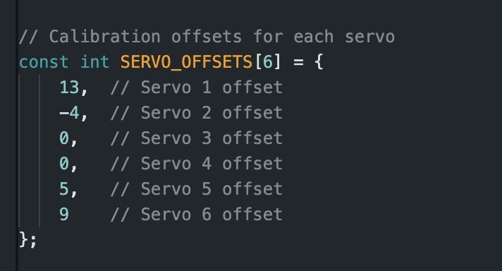
I have attached the code I used to calibrate and manually move the servos using Arduino IDE - the offsets were noted and I carried them forward into future code development.
Download Link for servo_test3This code can be used to calibrate the servos and takes into account the orientation the servos are mounted and the range of motion needed in them which can all be controlled and figured out using this code - this information will then be used to create the final version of the code.
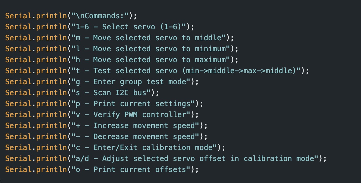
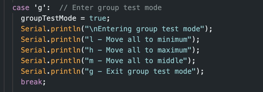
There are also keyboard controls that we can input using the serial monitor in Arduino IDE. See screenshots below - the first image shows the controls to move each servo individually to find their range of motion and set the mid or neutral location - the second set of controls are for moving all servos as a group - this can be used when you first attach the top plate to the hexapod - I also included the Servo Offsets I'm using for my setup - this will be different for each individual hexapod setup.
Week 17
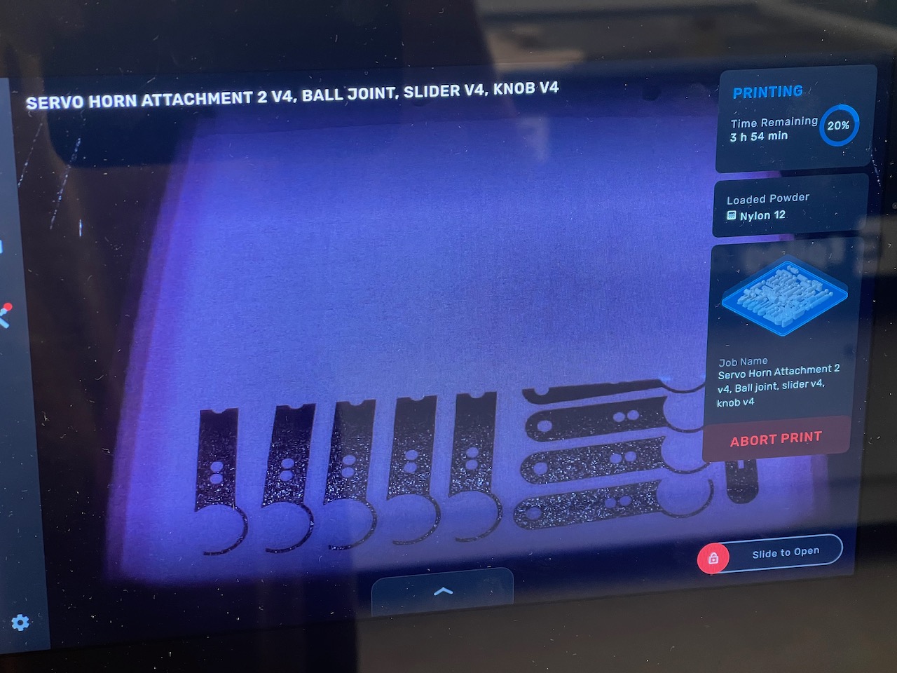
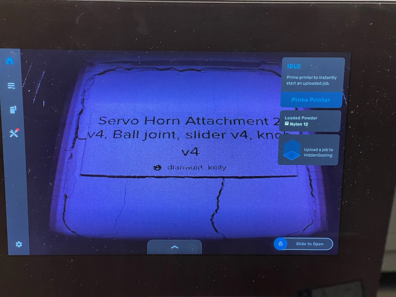
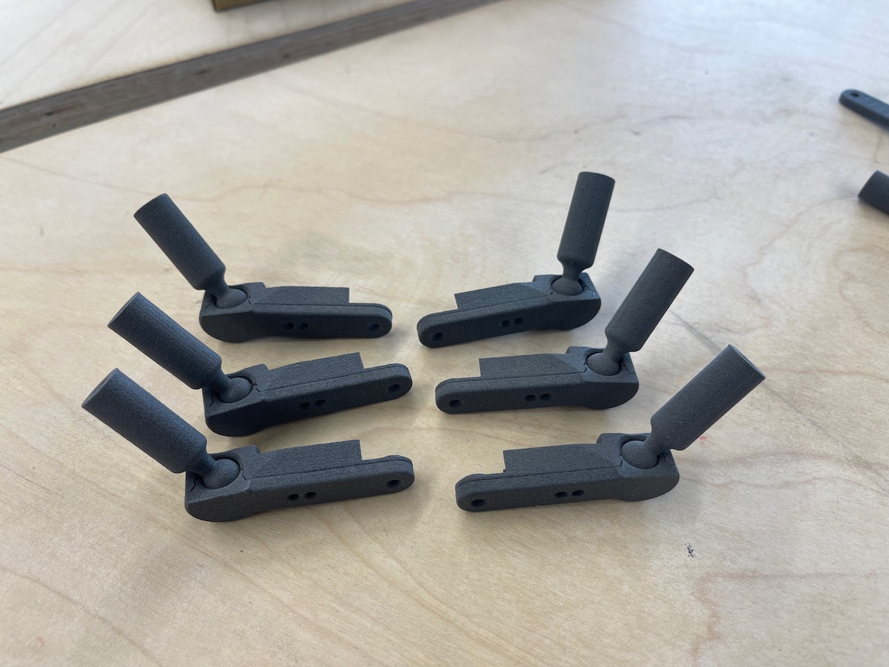
Below images show the servo arm attachments being printed. I'm using the Form 1 using Nylon 12 powder from FormLabs. I chose this as I figured it would be stronger than FDM printed parts and I would get more accurate parts.

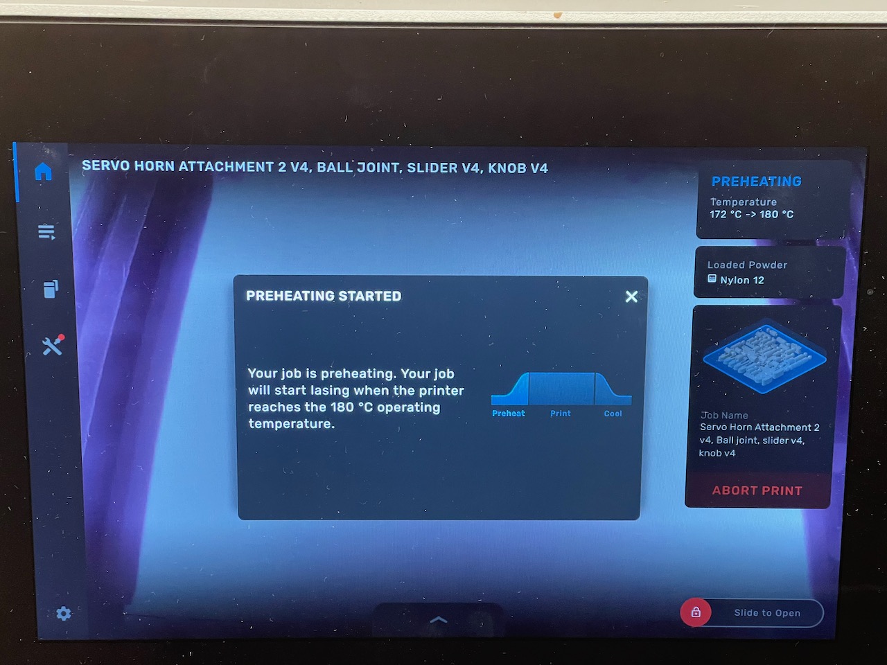
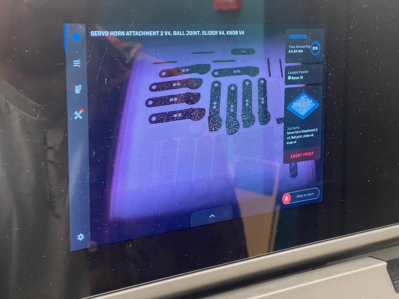
Above is a view on the Form 1 printer screen as the laser beam is passing over the powder. The print is in progress.
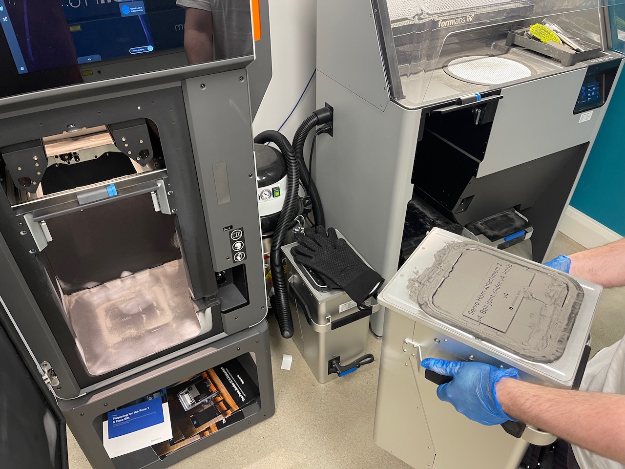
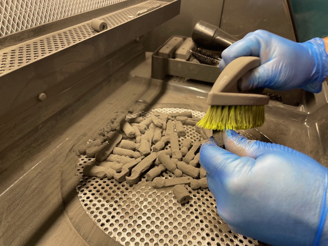
The next morning the parts are ready to be removed - see the images below.
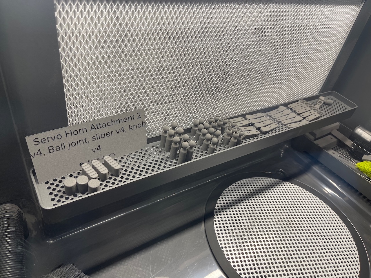
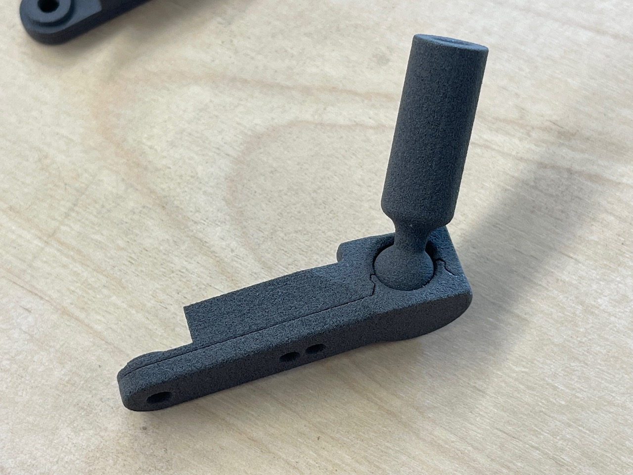
This was one of the ball joints I designed to hold an M3 hex head screw to glue into the carbon rod and give additional support and strength to the ball joint - note the deformation of the part - this was likely due to print orientation and wall thickness/shrinkage issues when printing. Not sure if I will use these ones. I also printed a set without this hole for the M3 hex head - I will use these ones for now.
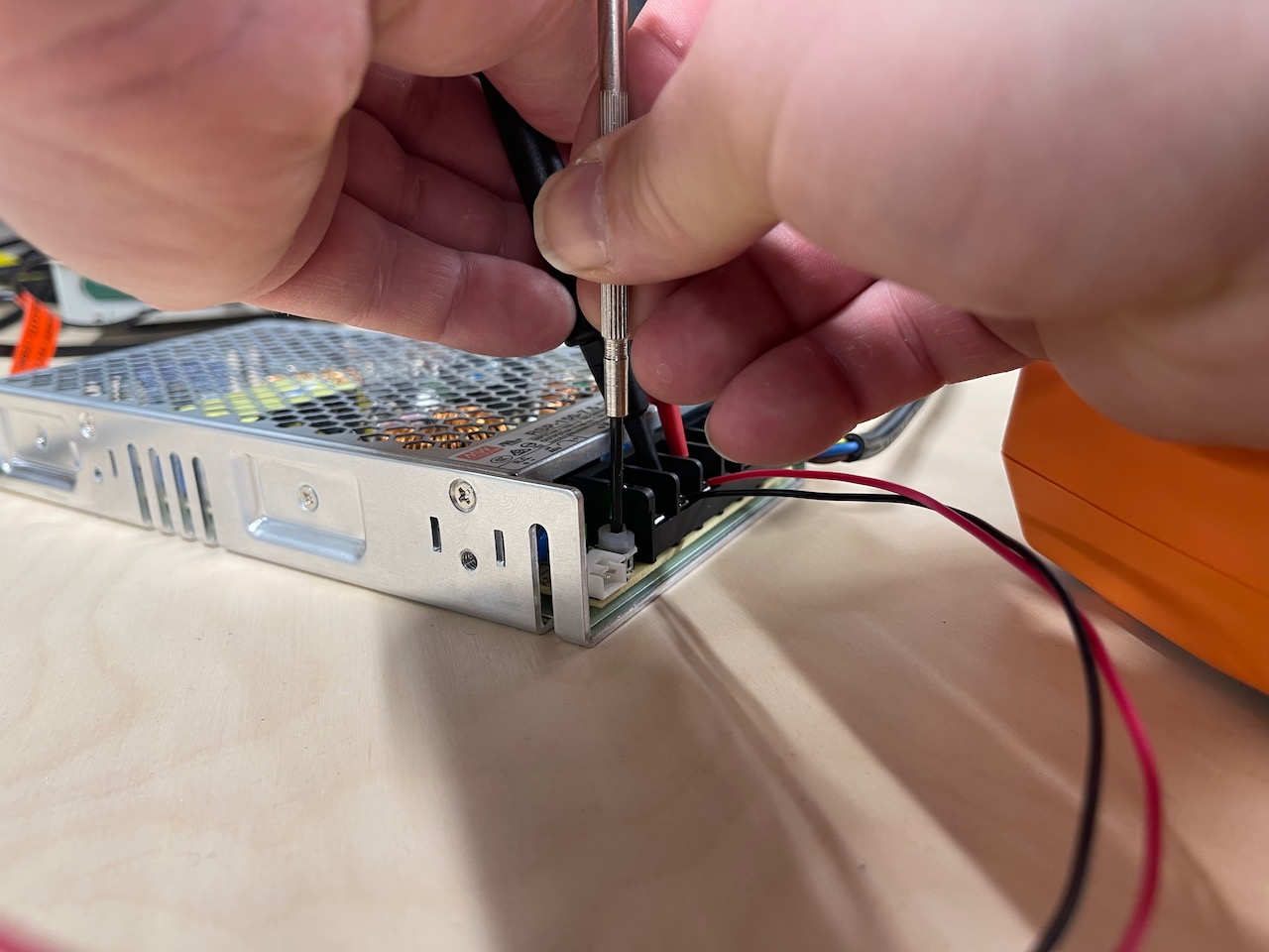
Setting the output power on the Mean Well power supply to 7.2V the voltage the servos require to operate.
Supply side time... daily schedule and
do as much as you can
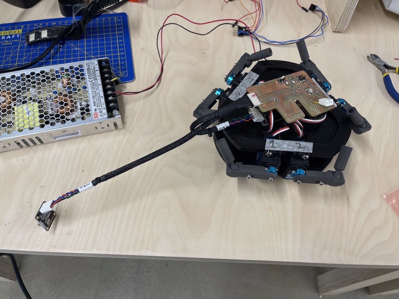
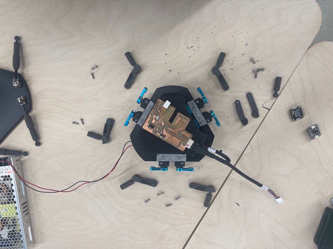
It became apparent at this point that I would not be able to produce a bespoke PCB board for this project - was not going to have enough time - so I would produce a cable that I would run both the BNO085 and the Servo Controller from the one port on the F board - this would be a temporary solution until I could get a PCB board made.
Below are images of an initial makeshift cable I created with the jumper cables and a breakout board extension port from the lab.
This allowed me to test the full setup using the test code we created earlier.
I had some issues when I first ran the full extent code - breakage - one of the ball joints broke see video below - I would need to reduce both the upper and lower range of motion for the servos to prevent this - back to the code.
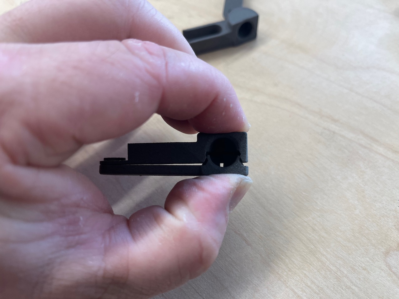
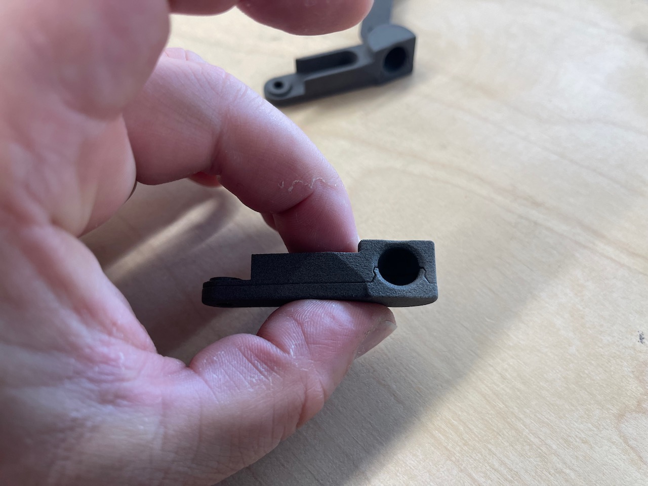
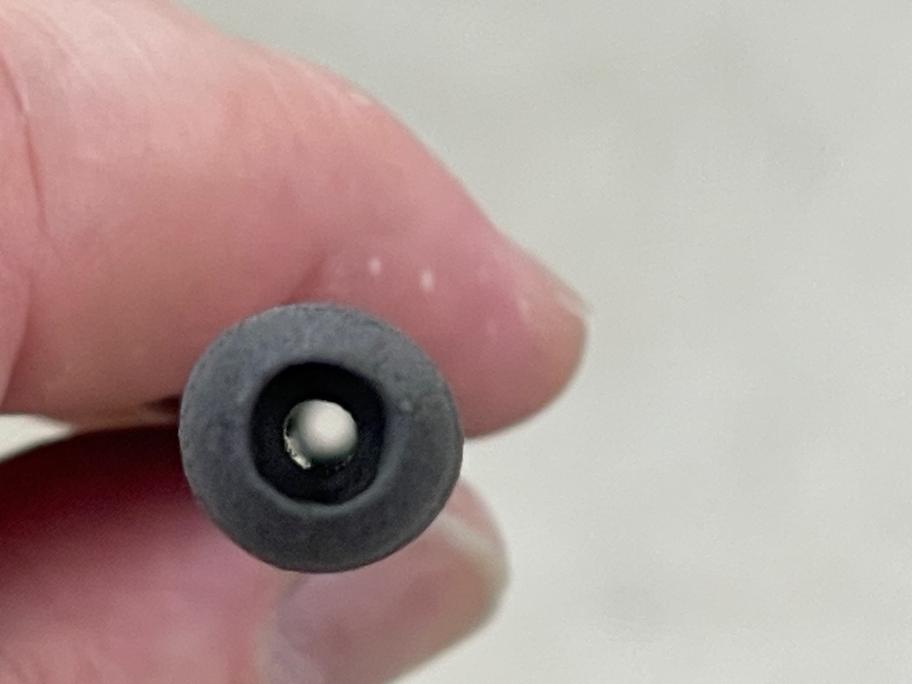
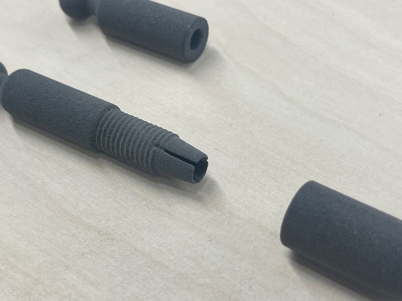
I also figured I would need longer connectors for the carbon rod as these were falling out - I also wanted a better method of connecting them to the rods that didn't require epoxy or glue - so I quickly drew up a two-part threaded locking mechanism to hold them in place.
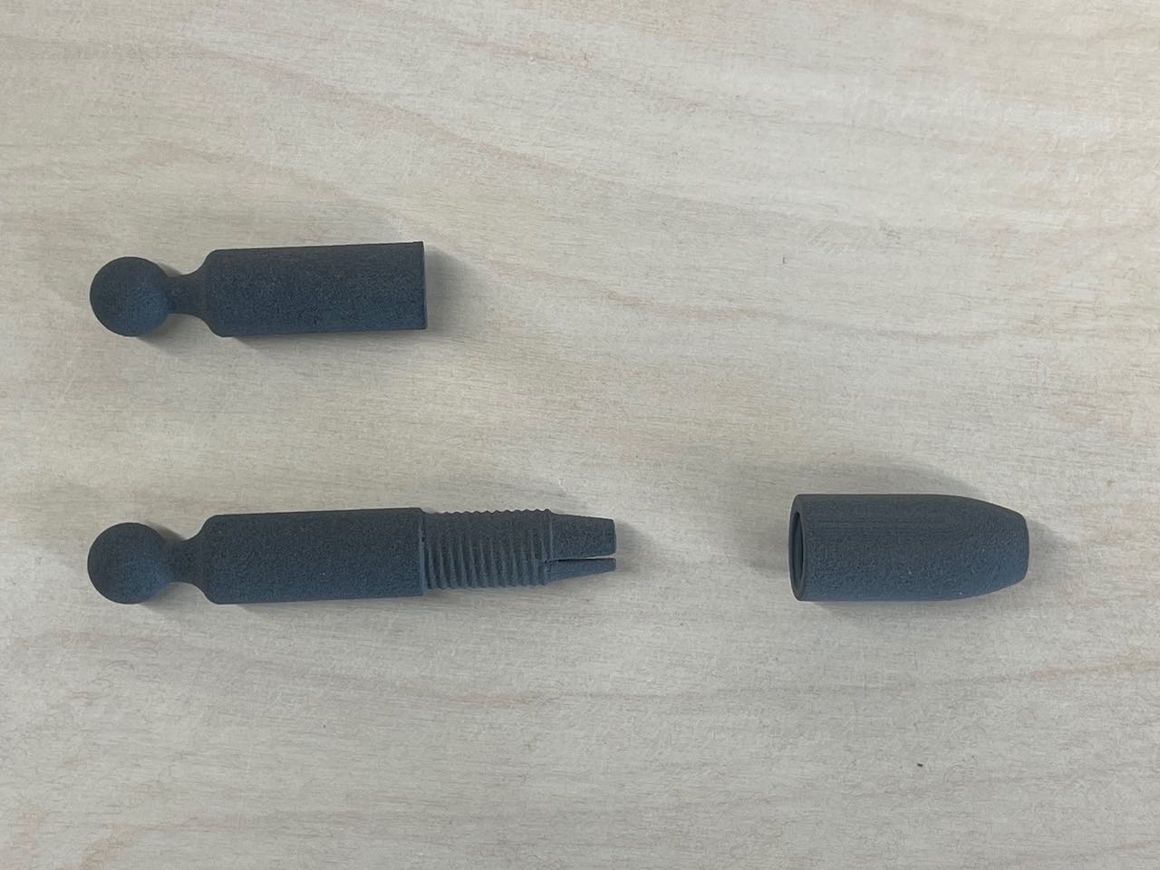
Below is an image of the original ball joint connector I designed and below is the redesigned model with a screw clamp to grip the carbon rod - this will also use this to hold the rod in place but also allow it to be removed if needed - I figured it's a better choice than using epoxy.
See screen recording of the CAD modelling process
I had the full CAD done at this stage below is a screen recording of playback in Autodesk Fusion.
At this point it's time to get the geometry setup for the inverse kinematics code.
I have attached the code I used to set up the geometry for the inverse kinematics code - this is the code that will be used to control the servos and the hexapod - it is a work in progress and will be updated as I go along.
I used a skeleton sketch in Autodesk Fusion to measure the various line lengths that would be needed and to set the angles between the servos and the joints on both the top and bottom plates.
These are theoretical plates as they need to intersect the joint locations - so I set up construction planes in Fusion at the universal joints and at the servo arm attachment point and drew wireframe sketch to get accurate measurements.
Download Link for the Stewart platform inverse kinematics codeThis code required some back and forth in Cursor AI with testing to get the alignment correct and the orientation of the BNO085 correct.
I ultimately fed Cursor AI some screenshots of the CAD model for it to understand the setup.
Once I did this I was able to get the manual control working correctly - I did have to rotate the BNO085 180 degrees so the light pipe no longer works - I'll fix this in a later iteration of the model.
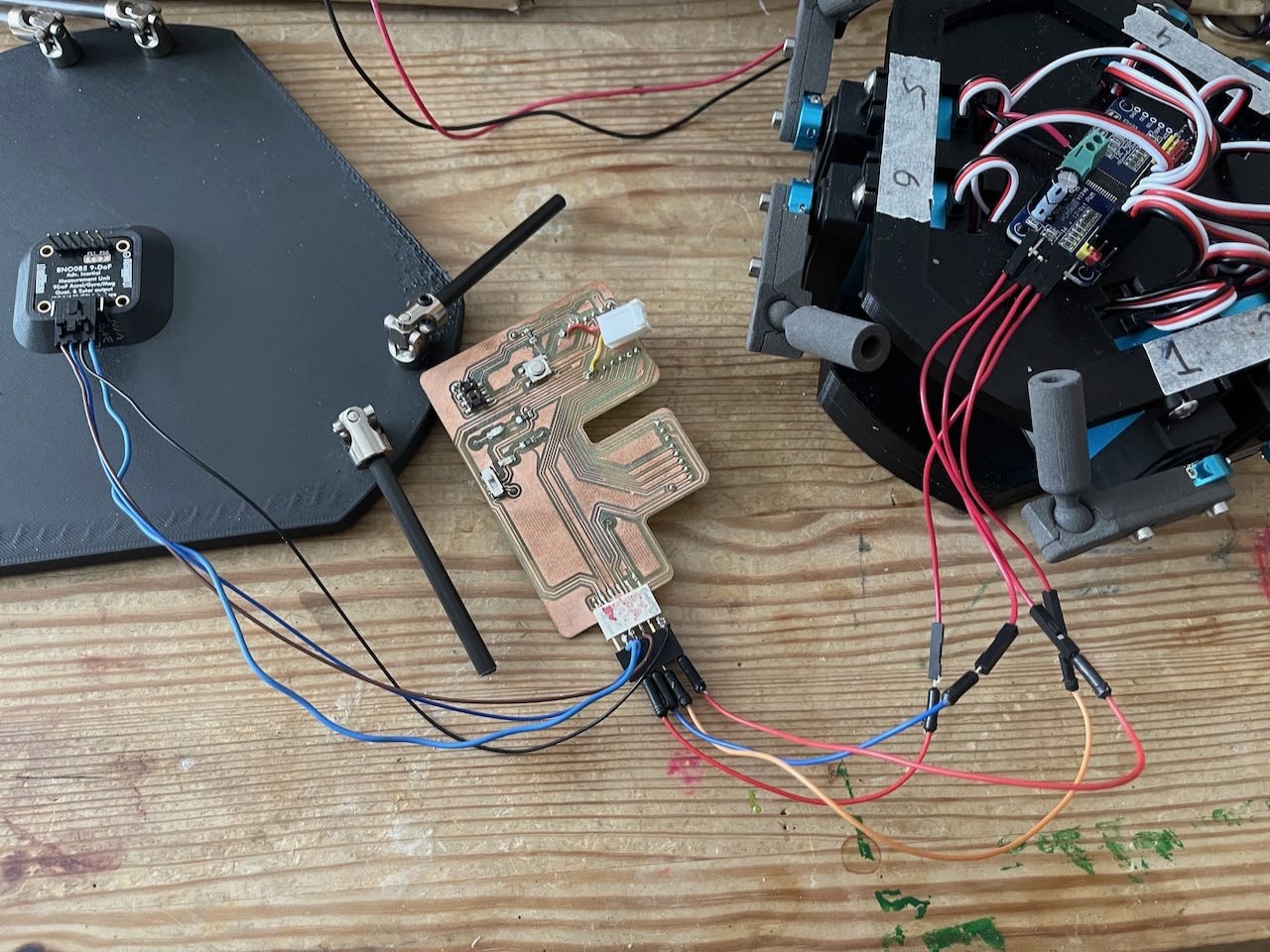
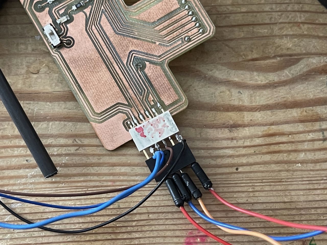
Another thing I had to do was create a bespoke cable - something a little better than what I was testing with earlier - this is what I came up with.
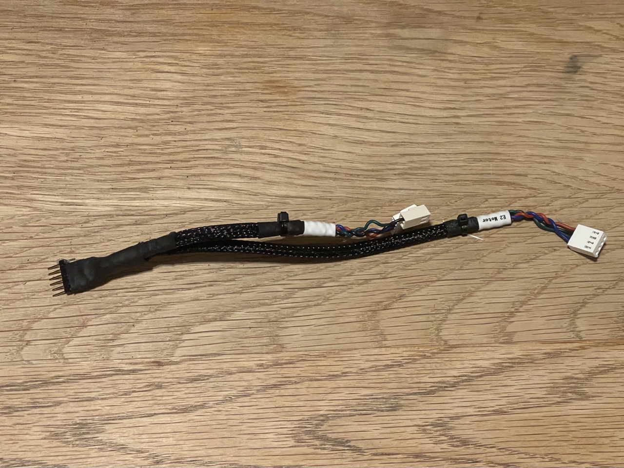
It would carry power and signal from the F board to the BNO085 and the Servo Controller board.
Trying to figure out the orientation for the F board before I design a board mount - But I have a new cable that I put together.
The 'F' board mount printed and holding the board in place - it is designed to snap fit, no glue or screws needed.
Once I got the assembly back together with the new ball joint connectors I was able to get back to testing out the code. There were several iterations to get the board moving correctly. I did eventually get there however. and below is a video of the first proper move of the steady platform while holding something on the top plate.
The code was working - a little shaky but it was holding the platform level for the most part... success...
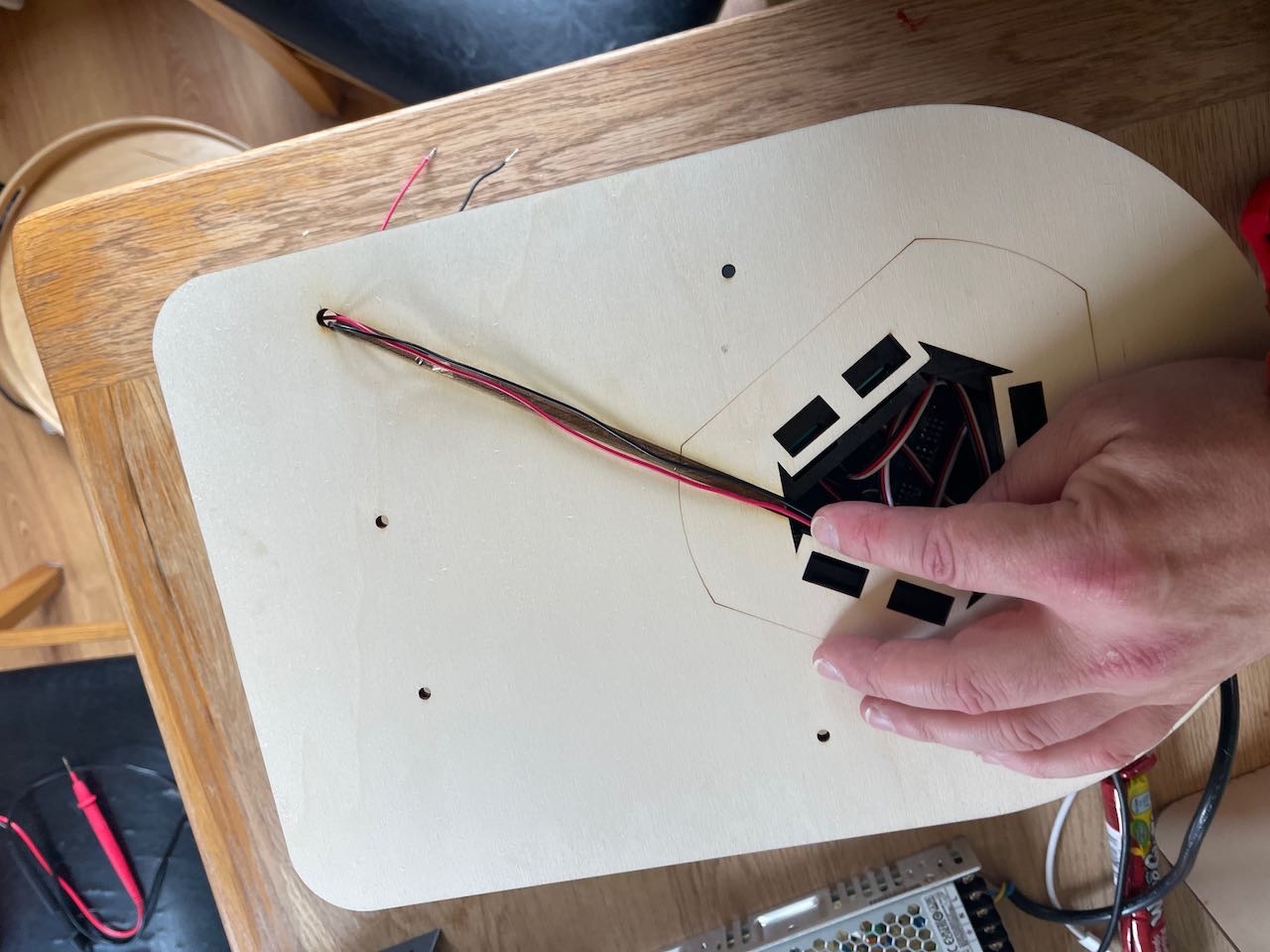
I went on to produce the laser cut base board to mount the Power Supply and the Stewart platform in place. And then we could take the platform for a drive on the road to see how it stood up to the bumps and motion experienced when driving on the road.
From my initial design I did cut a second ply sheet to rotate the Stewart platform 180 deg as I thought it looked better with the two servos facing the front and the power supply to the back I also took the opportunity to raster in a track with the laser cutter for the cable between the power supply and the Stewart Platform to be hidden between the two laser cut boards.
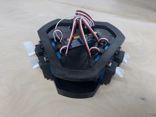
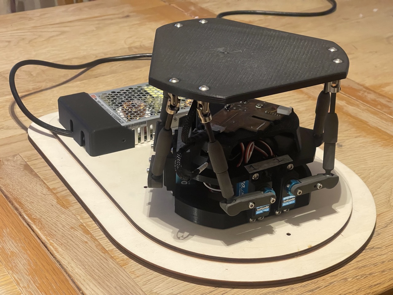
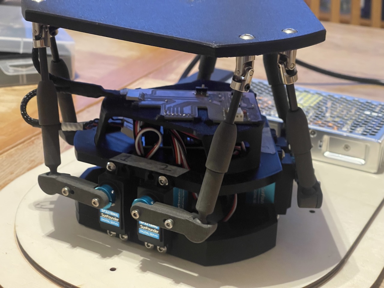
Some images of the final project assembled and ready for the drive on the road.
The Steady Top Stewart Platform is mounted on the bench in the back of the van - for this I used some Command hanging adhesive strips - they are hook and loop strips stuck to both the underside of the platform and the bench top - this is a temporary fixture so it can be removed easily.
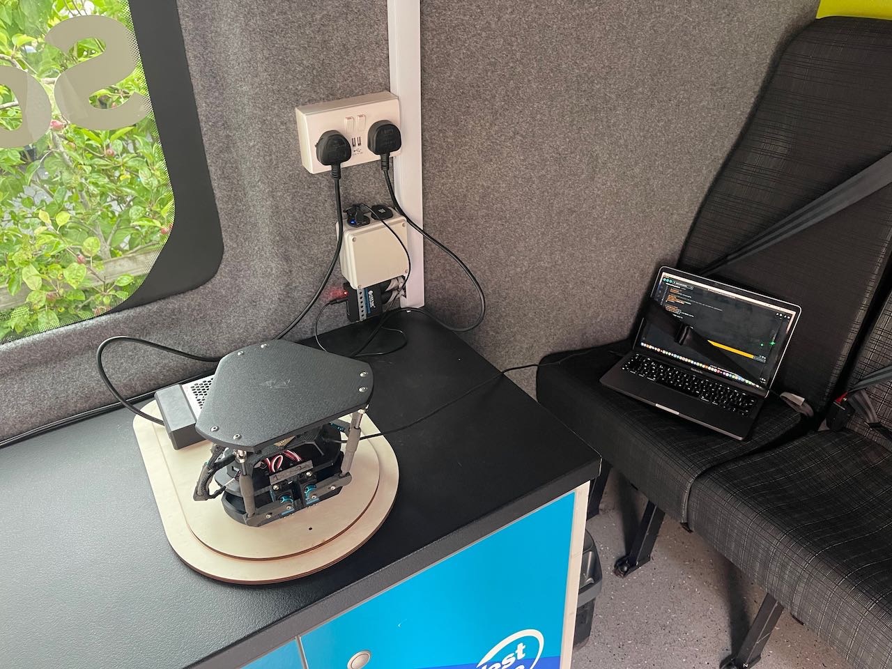
Time to test this on the move...
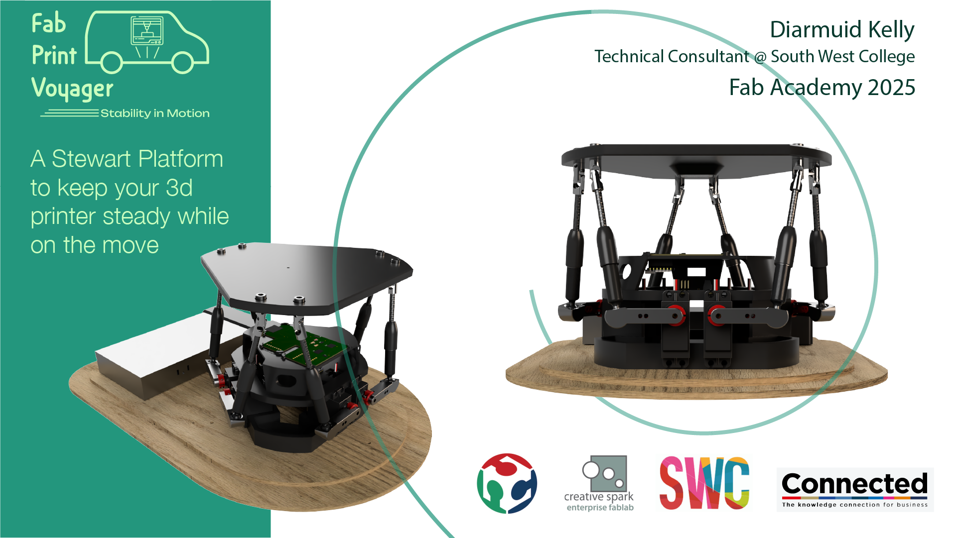
Final Project Slide
Final Project Video
Final Project CAD
Below you can see the exploded view CAD model and a download link of the original CAD files in Autodesk Fusion format.
File download link - Steady Top - Stewart Platform
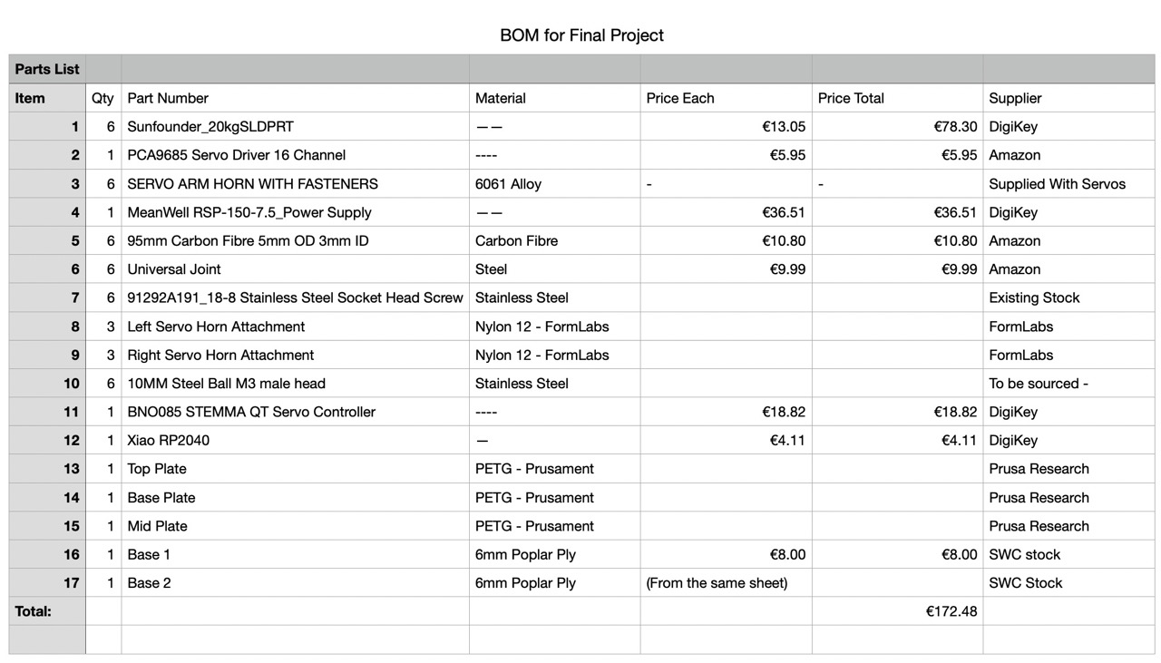
Final Project BOM
Final Project Code
Project Code Download Link: Steady Top - Stewart Platform
Below we can see the final version of the code that I produced with the help of Cursor AI - The entire coding process took around 2-3 weeks in total, when you take into account the initial setup of the servos - refining the orientation of the hexapod geometry - and the location and orientation of the BNO085 IMU. The inverse kinematics for manual control and setting up the board geometry. With my level of coding ability I would have struggled to produce this code without the help of Cursor AI.
//Code for self-levelling Stewart platform.
//Diarmuid Kelly - Fab Academy 2025
//Written with the help of Cursor AI
//Created 7th June 2025

#include <Wire.h>
#include <Adafruit_PWMServoDriver.h>
#include <Adafruit_BNO08x.h>

// Pin Definitions
#define BUTTON_PIN D7
#define LED_PIN D6

// Servo and IMU instances
Adafruit_PWMServoDriver pwm = Adafruit_PWMServoDriver();
Adafruit_BNO08x bno08x;
sh2_SensorValue_t sensorValue;

// Servo config (adjust as needed)
#define SERVO_FREQ 50
#define INVERTED_MIN 560
#define INVERTED_MAX 440
#define NORMAL_MIN 140
#define NORMAL_MAX 260
int SERVO_OFFSETS[6] = {13, -4, 0, 0, 5, 9}; // Example offsets

// Control parameters
const float MAX_ANGLE = 15.0; // deg
const float Kp = 2.0;         // Proportional gain (tune as needed)
const float MOVEMENT_RANGE = 25; // Max servo movement for max error
const unsigned long UPDATE_RATE = 50; // ms
const float MAX_SAFE_TILT = 10.0; // degrees, soft stop limit

// IMU variables
float grav_x = 0, grav_y = 0, grav_z = 0;
float measured_pitch = 0, measured_roll = 0;
float pitch_offset = 0, roll_offset = 0;
float zeroed_pitch = 0, zeroed_roll = 0;

// Levelling control
bool isLevelling = false;
unsigned long lastUpdate = 0;

void setup() {
  Serial.begin(115200);
  while (!Serial && millis() < 3000) delay(10);
  Serial.println("\nStewart Platform Closed-Loop Levelling");
  Serial.println("Initializing...");

  pinMode(BUTTON_PIN, INPUT_PULLDOWN);
  pinMode(LED_PIN, OUTPUT);
  digitalWrite(LED_PIN, LOW);

  Wire.begin();
  Serial.println("I2C initialized");

  pwm.begin();
  pwm.setOscillatorFrequency(27000000);
  pwm.setPWMFreq(SERVO_FREQ);
  delay(100);

  if (!bno08x.begin_I2C()) {
    Serial.println("Failed to find BNO085 chip");
    while (1) { delay(10); }
  }
  Serial.println("BNO085 found!");
  if (!bno08x.enableReport(SH2_GRAVITY)) {
    Serial.println("Could not enable gravity vector");
  }

  // Set initial servo positions to centre
  for (int i = 0; i < 6; i++) {
    int pulse = (i % 2 == 0) ? (INVERTED_MIN + INVERTED_MAX) / 2 : (NORMAL_MIN + NORMAL_MAX) / 2;
    setServoPulse(i, pulse + SERVO_OFFSETS[i]);
  }

  Serial.println("\nPress button or send 'l' to toggle levelling. Press 'z' to zero IMU.");
  Serial.println("Format: Pitch,Roll,ZeroedPitch,ZeroedRoll,Servo1,Servo2,Servo3,Servo4,Servo5,Servo6");
}

void loop() {
  // Button toggles levelling
  static bool lastButtonState = LOW;
  bool buttonState = digitalRead(BUTTON_PIN);
  if (buttonState && !lastButtonState) {
    isLevelling = !isLevelling;
    digitalWrite(LED_PIN, isLevelling ? HIGH : LOW);
    Serial.println(isLevelling ? "Levelling ENABLED" : "Levelling DISABLED");
    delay(200); // debounce
    if (!isLevelling) moveServosToNeutral();
  }
  lastButtonState = buttonState;

  // Serial commands
  if (Serial.available() > 0) {
    char cmd = Serial.read();
    if (cmd == 'l') {
      isLevelling = !isLevelling;
      digitalWrite(LED_PIN, isLevelling ? HIGH : LOW);
      Serial.println(isLevelling ? "Levelling ENABLED" : "Levelling DISABLED");
      if (!isLevelling) moveServosToNeutral();
    } else if (cmd == 'z') {
      pitch_offset = measured_pitch;
      roll_offset = measured_roll;
      Serial.println("IMU zeroed to current orientation!");
    }
  }

  // IMU update and levelling
  if (millis() - lastUpdate >= UPDATE_RATE) {
    lastUpdate = millis();
    updateIMU();
    if (isLevelling) {
      closedLoopLevelling();
    }
    printStatus();
  }
}

void updateIMU() {
  while (bno08x.getSensorEvent(&sensorValue)) {
    if (sensorValue.sensorId == SH2_GRAVITY) {
      grav_x = sensorValue.un.gravity.x;
      grav_y = sensorValue.un.gravity.y;
      grav_z = sensorValue.un.gravity.z;
      measured_pitch = atan2(grav_y, sqrt(grav_x * grav_x + grav_z * grav_z)) * 180.0 / PI;
      measured_roll  = atan2(grav_x, grav_z) * 180.0 / PI;
      zeroed_pitch = measured_pitch - pitch_offset;
      zeroed_roll  = measured_roll - roll_offset;
    }
  }
}

void closedLoopLevelling() {
  // Calculate error (target is zeroed)
  float pitch_error = 0.0 - zeroed_pitch;
  float roll_error  = 0.0 - zeroed_roll;
  // Proportional control with soft stop
  float pitch_cmd = constrain(Kp * pitch_error, -MAX_SAFE_TILT, MAX_SAFE_TILT);
  float roll_cmd  = constrain(Kp * roll_error,  -MAX_SAFE_TILT, MAX_SAFE_TILT);
  // Calculate servo positions
  int servoPositions[6];
  calculateServoPositions(pitch_cmd, roll_cmd, servoPositions);
  moveAllServosSmoothly(servoPositions);
}

void calculateServoPositions(float pitch, float roll, int* positions) {
  float servoAnglesDeg[6] = { -10.6, 10.6, 109.4, 130.6, 229.4, 250.6 }; // Update as per your geometry
  float pitchFactor = pitch / MAX_ANGLE;
  float rollFactor = roll / MAX_ANGLE;
  float movement = MOVEMENT_RANGE;
  for (int i = 0; i < 6; i++) {
    float theta = servoAnglesDeg[i] * PI / 180.0;
    float move = -rollFactor * cos(theta) - pitchFactor * sin(theta);
    int pulse;
    if (i % 2 == 0) {
      pulse = map(move * movement, -movement, movement, INVERTED_MAX, INVERTED_MIN);
    } else {
      pulse = map(move * movement, -movement, movement, NORMAL_MIN, NORMAL_MAX);
    }
    positions[i] = pulse + SERVO_OFFSETS[i];
  }
}

void moveAllServosSmoothly(int* targetPositions) {
  static int currentServoPositions[6] = {0, 0, 0, 0, 0, 0};
  static bool firstRun = true;
  if (firstRun) {
    for (int i = 0; i < 6; i++) {
      currentServoPositions[i] = targetPositions[i];
      setServoPulse(i, targetPositions[i]);
    }
    firstRun = false;
    return;
  }
  bool servosMoving = true;
  while (servosMoving) {
    servosMoving = false;
    for (int i = 0; i < 6; i++) {
      if (abs(targetPositions[i] - currentServoPositions[i]) > 2) {
        servosMoving = true;
        int step = 2;
        int distance = abs(targetPositions[i] - currentServoPositions[i]);
        if (distance > 20) step = 4;
        else if (distance < 5) step = 1;
        if (targetPositions[i] > currentServoPositions[i]) currentServoPositions[i] += step;
        else currentServoPositions[i] -= step;
        setServoPulse(i, currentServoPositions[i]);
      }
    }
    delay(20);
  }
  for (int i = 0; i < 6; i++) {
    setServoPulse(i, targetPositions[i]);
    currentServoPositions[i] = targetPositions[i];
  }
}

void setServoPulse(int servo, int pulse) {
  pwm.setPWM(servo, 0, pulse);
}

void printStatus() {
  Serial.print(zeroed_pitch); Serial.print(",");
  Serial.print(zeroed_roll); Serial.print(",");
  Serial.print(measured_pitch); Serial.print(",");
  Serial.print(measured_roll); Serial.print(",");
  // Print servo positions (optional, here just print zeros for placeholder)
  Serial.print("0,0,0,0,0,0\n");
}

void moveServosToNeutral() {
  int neutralPositions[6];
  for (int i = 0; i < 6; i++) {
    int pulse = (i % 2 == 0) ? (INVERTED_MIN + INVERTED_MAX) / 2 : (NORMAL_MIN + NORMAL_MAX) / 2;
    neutralPositions[i] = pulse + SERVO_OFFSETS[i];
  }
  moveAllServosSmoothly(neutralPositions);
}
Acknowledgements
I would like to thank the following people for their help and support during Fab Academy:
- Local instructor @ Creative Spark Industry Fab Lab - Oscar Diaz
- Global Instructor - Rulindana Lambert
- All the team at Global Open Time - for their help and support
- All the staff at Creative Spark Industry Fab Lab - for their help and support
- South West College - and the Connected Fund for their support in funding me to take part in the Fab Academy - it was much appreciated