Week 2. Computer Aided Design
Let's learn some CAD...
Assignment
model (raster, vector, 2D, 3D, render, animate, simulate, ...) a possible final project
compress your images and videos
and post a description with your design files on your class page
Software
Adobe Fresco - https://www.adobe.com/uk/products/fresco.html
Sketchbook Pro - https://www.sketchbook.com/sketchbook-pro
Adobe Illustrator - https://www.adobe.com/uk/products/illustrator.html
Autodesk Fusion - https://www.autodesk.com/products/fusion-360/overview
Onshape - https://www.onshape.com/
Rhino3d - https://www.rhino3d.com/
Grasshopper - https://www.grasshopper3d.com/
FFMPEG - https://ffmpeg.org
We're going to select and evaluate 2D and 3D software this week.
2D packages will include Adobe Fresco (iPad), Sketchbook Pro (iPad) and Adobe Illustrator (Mac or PC).
3D packages will include Autodesk Fusion, Onshape, Rhino3D and Grasshopper.
I will also demonstrate image and video compression.
I will model some parts for potential final projects (I still haven't decided on the final project, but I think it will be a hexapod/Stewart platform).
We will start with a basic modelling of a solar panel system for the mobile fab lab. I scanned the van using photogrammetry, and you can see this process documented in later weeks. An .FBX file of the scanned van was imported into Fusion and aligned to the origin. A basic frame for the panels was modelled.
Onshape was used to model a solar panel found online that could be suitable for this application. This was done to explore software options. The file was exported from Onshape and imported into an Autodesk Fusion assembly.
We will also look at modelling and animating the hexapod or Stewart platform in Rhino and Grasshopper.
Autodesk Fusion
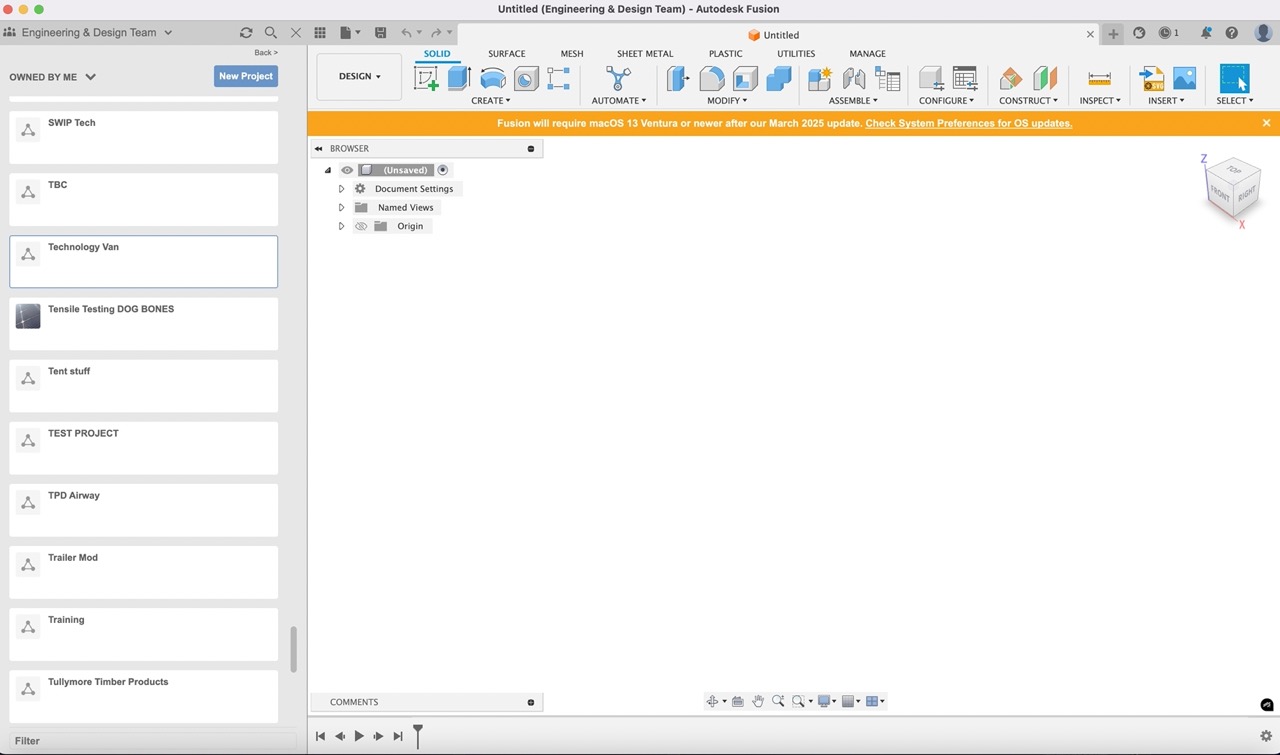
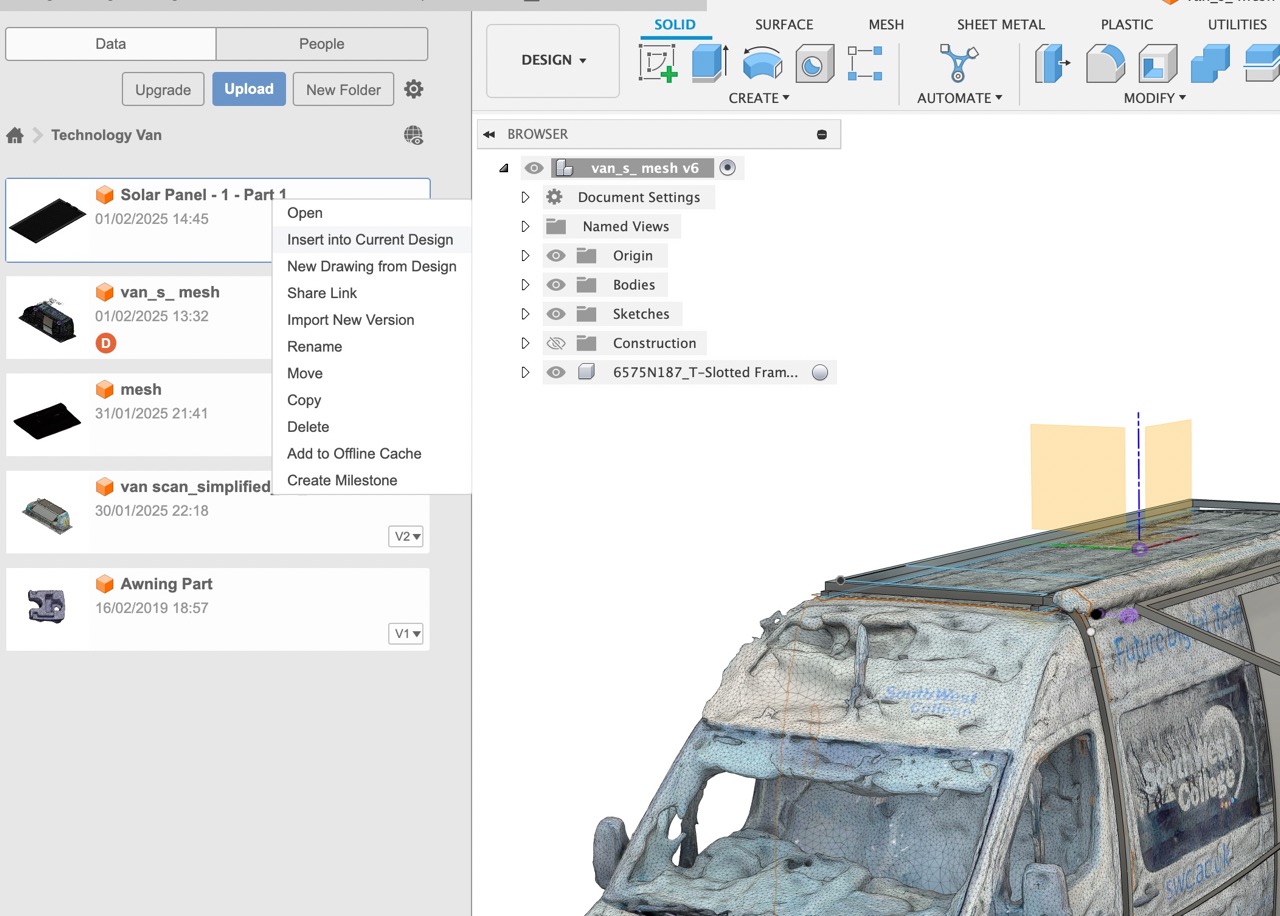
Created new project in the data panel called Technology Van
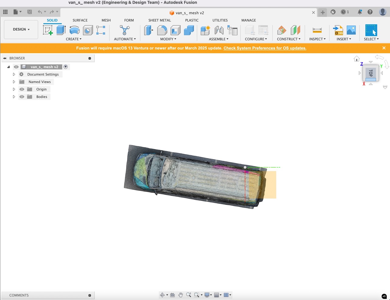
I then uploaded the 3d scan file of the van in .FBX format and opened this document.
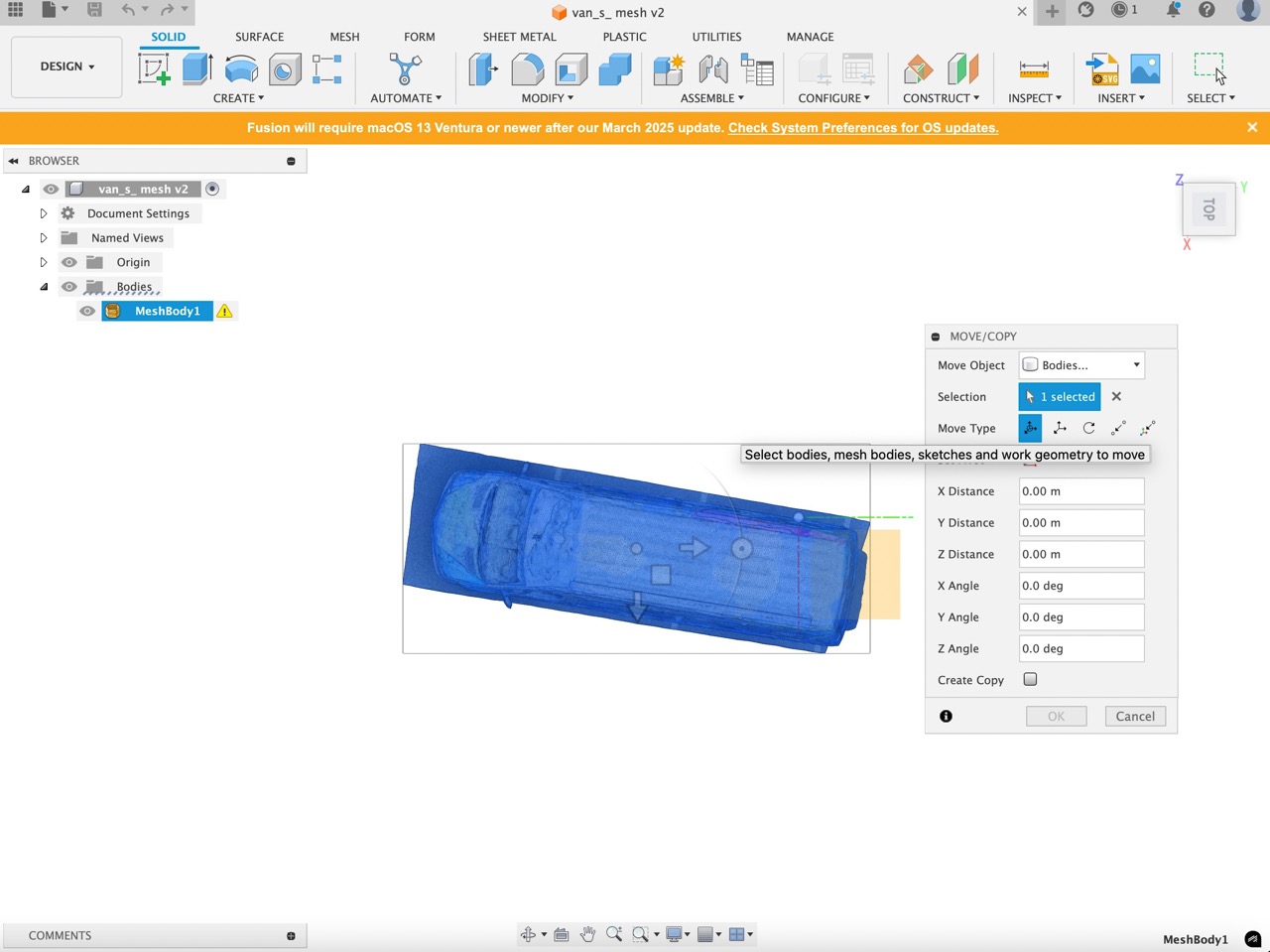
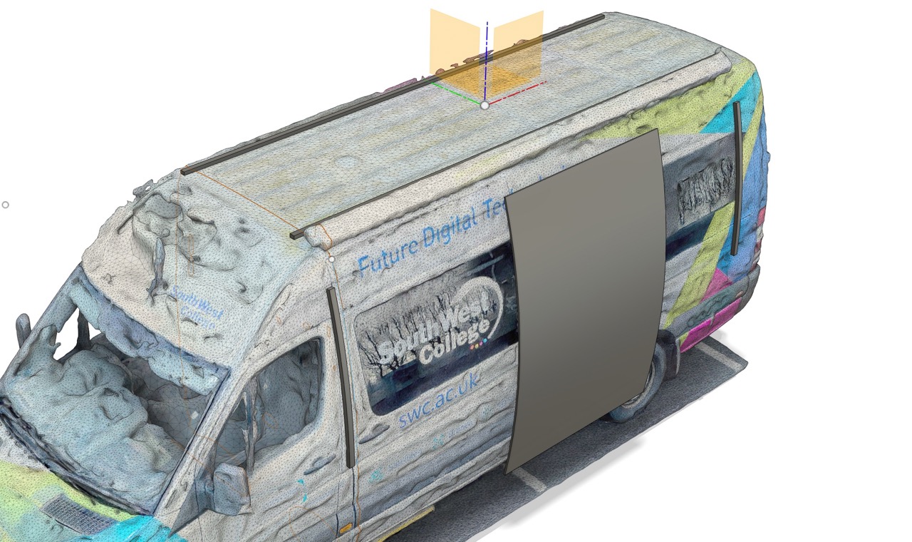
The scanned part needs to be aligned to the origin. Use the move command (type "m" on the keyboard for a shortcut) and select the mesh body to move.
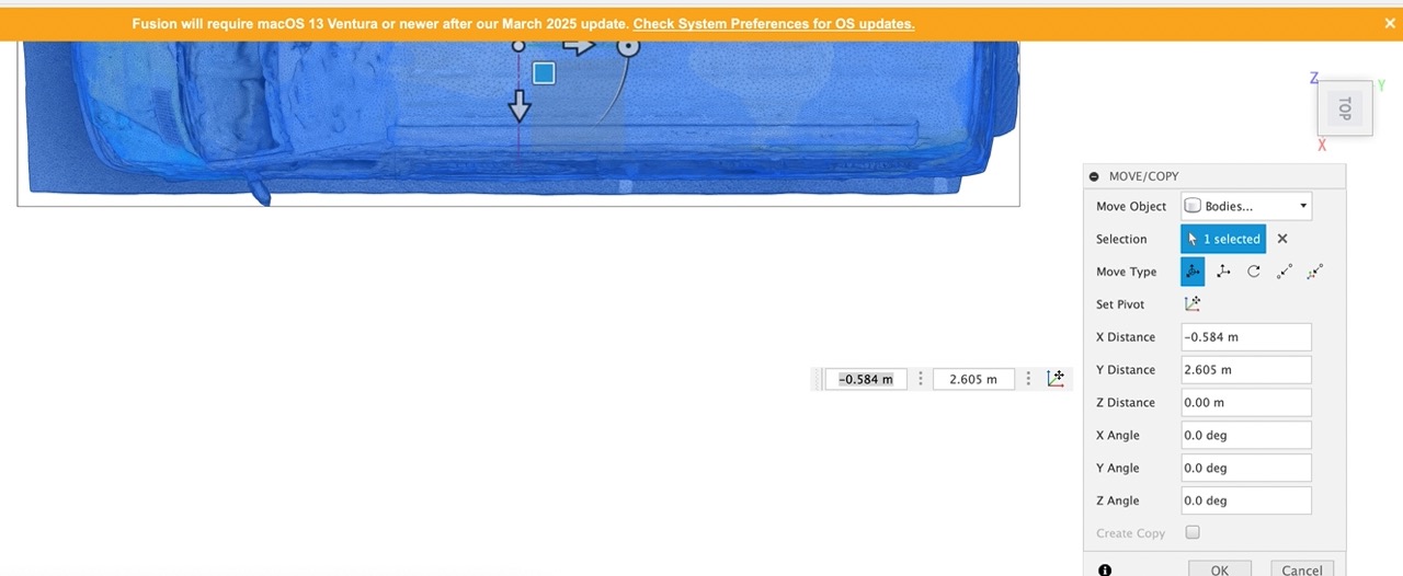
For this part, I will orient the mesh so the origin sits at the center of the roof.
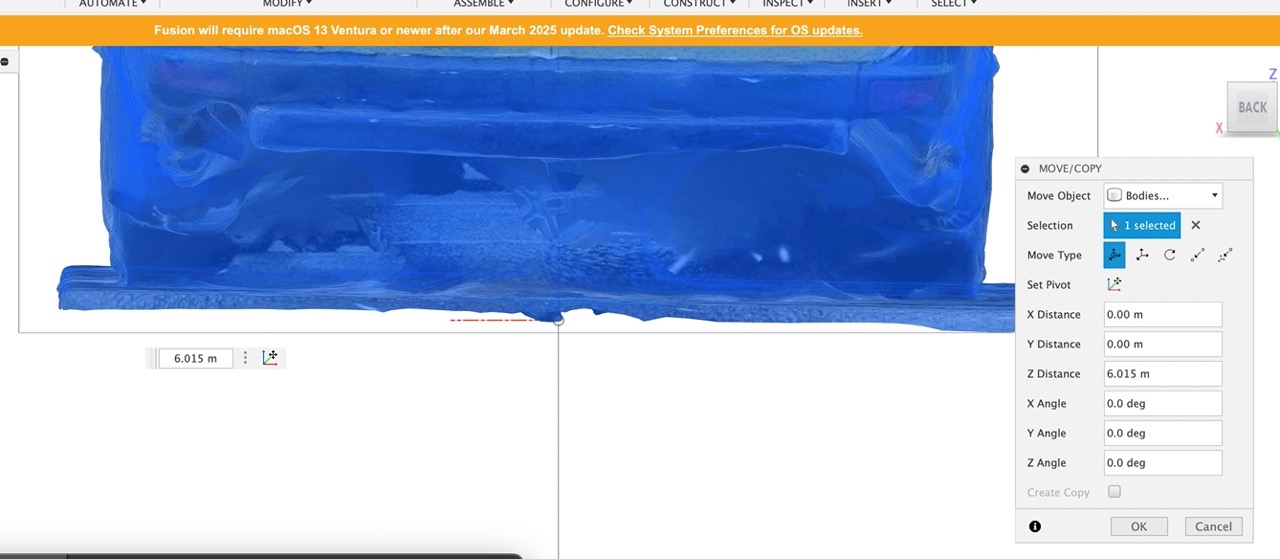
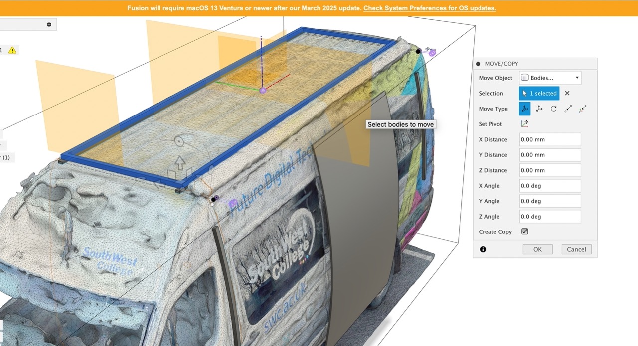
There is probably a more accurate way to do this, But I maneuver the part by eye. I use screen edges to align the van – just make sure the camera is set to orthographic and you are using the cube in the top right to set the view perpendicular (i.e., Top or Front).
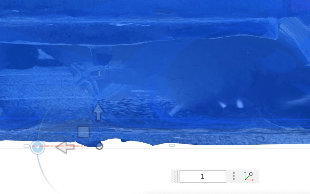
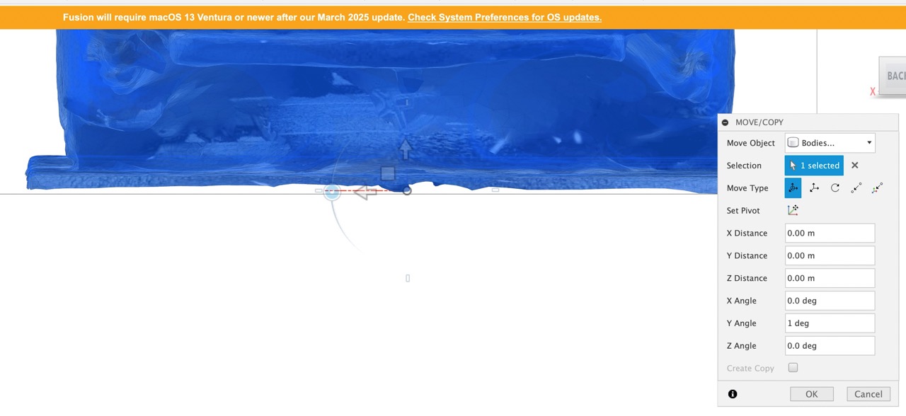
You can press the dot to rotate the part. It will likely jump to 2.5 degrees minimum. To move it in smaller increments, you will need to manually type the angle in the pop-up dialogue box. In this case, I neede to move 1 degree to get the front bumper aligned horizontally.
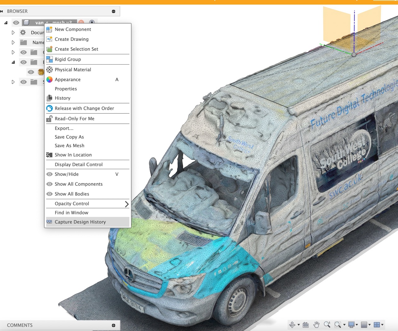
Once happy with the alignment, we need to start capturing design history. Right-click the part at the top of the browser; "Capture Design History" is at the bottom. This must be done for files that have been imported if you want to be able to edit features created.
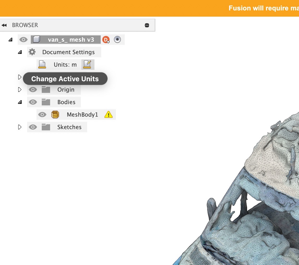
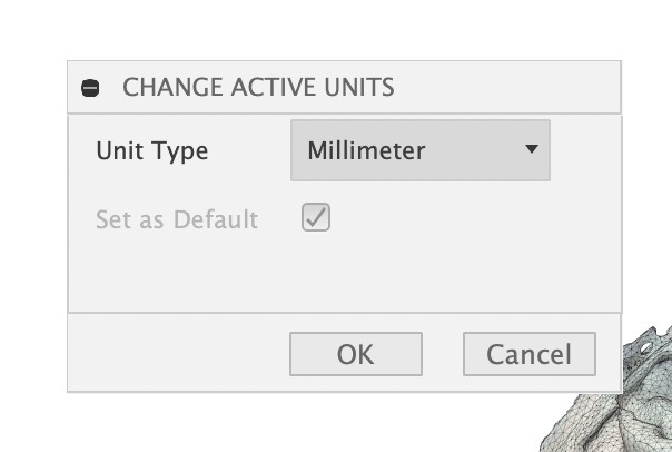
We also need to change the document units. This can be done in document settings by clicking the little arrow to access the drop-down. Set it to millimetres (or your preferred unit system).
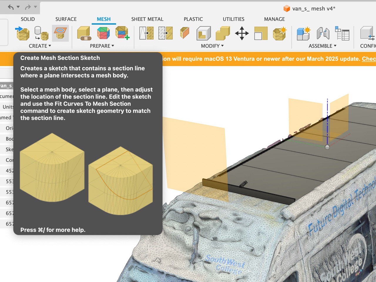
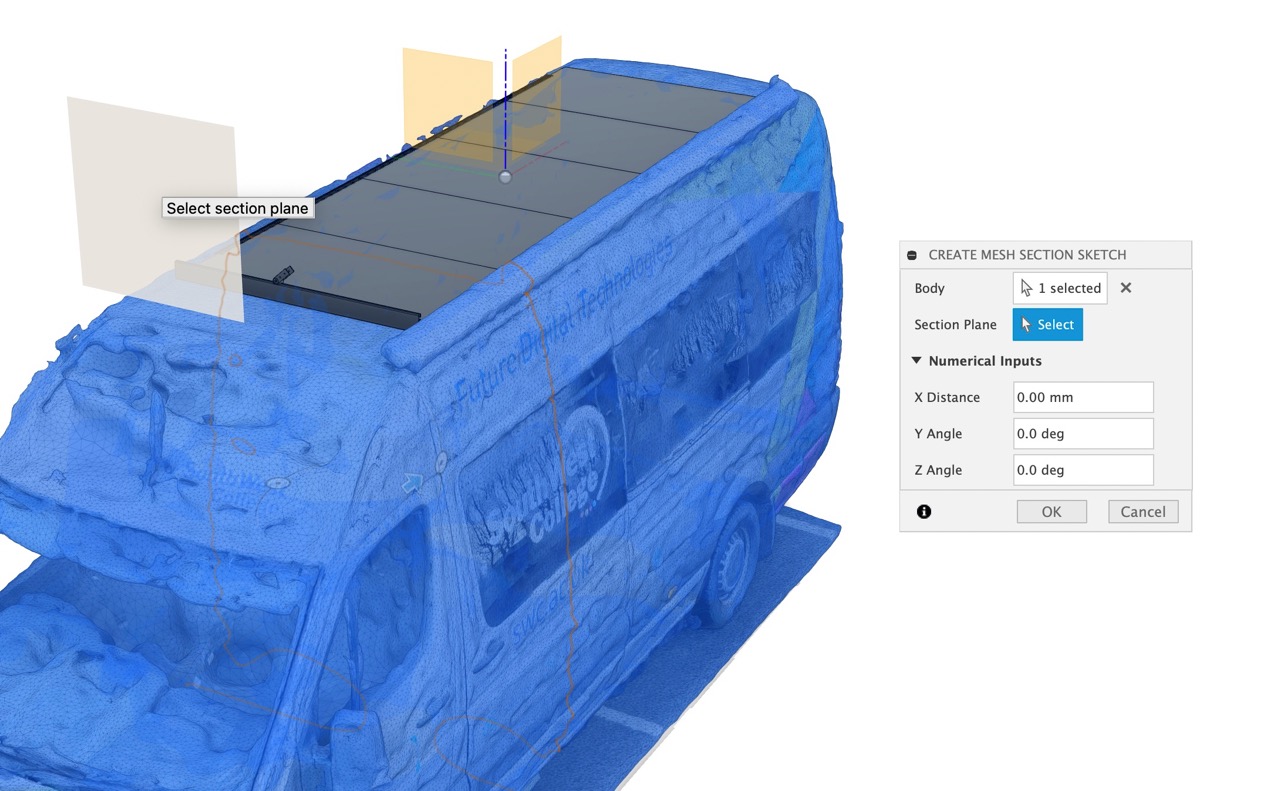
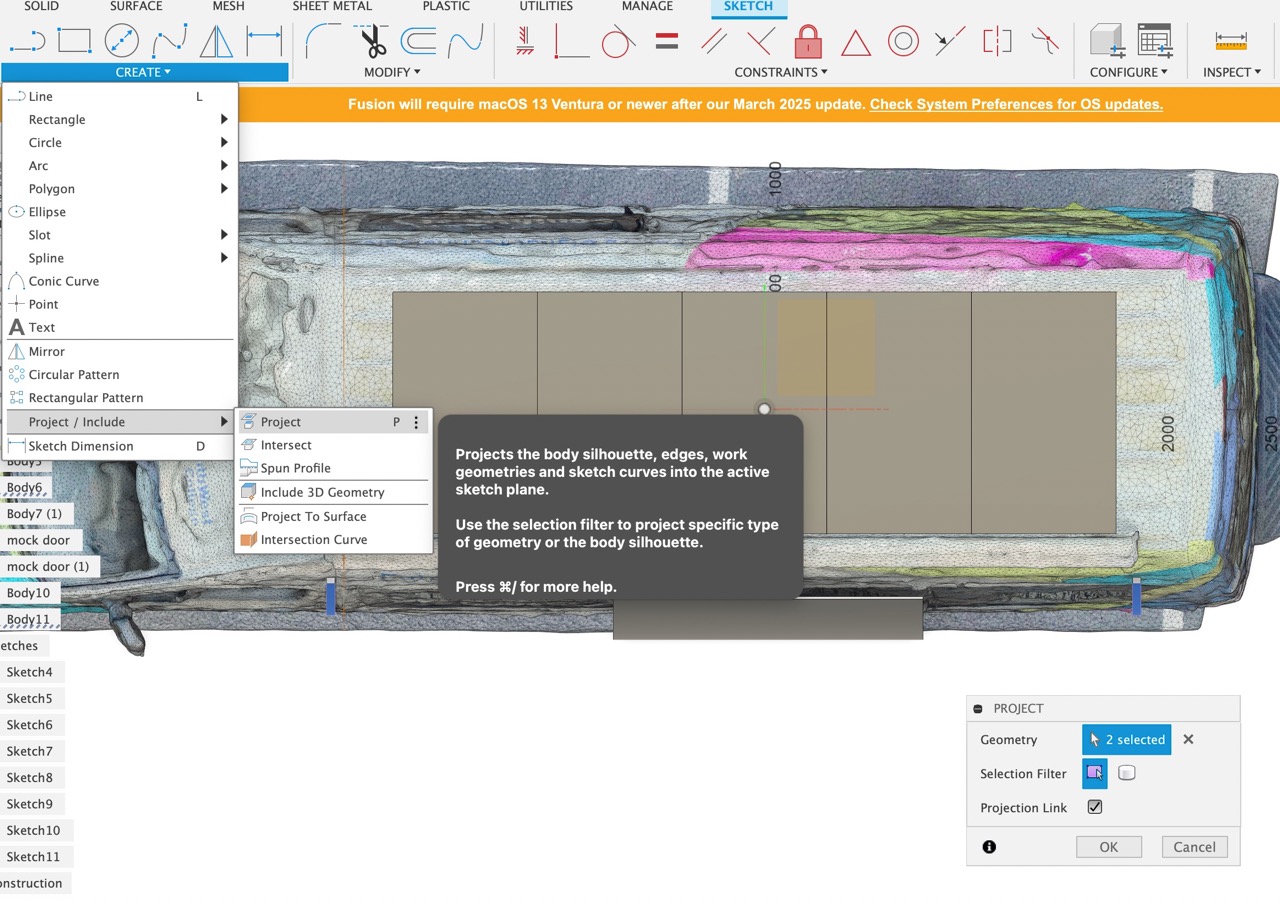
We are now ready to start modelling our part. I start by referencing the side panels of the van where it will be possible to mount support rails. To do this we switch to the "mesh tab" use the "create mesh selection tool" select a plane that intersects the geometry and move to the desired location with the arrow.
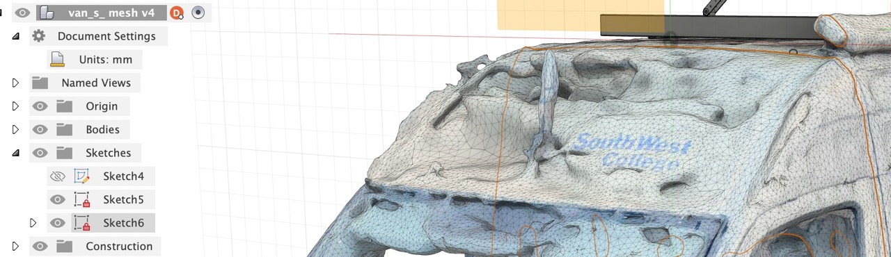
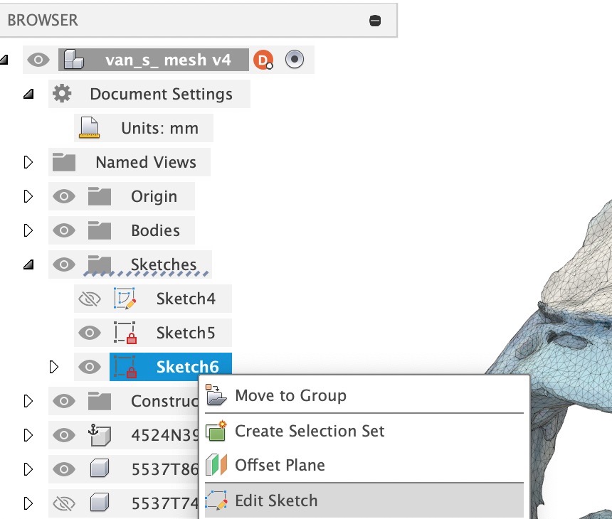
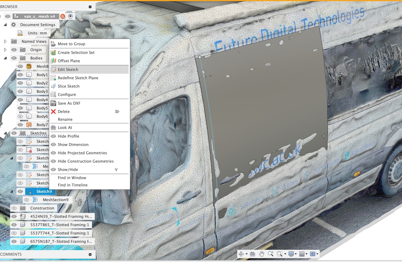
Click the little arrow beside the sketch folder in the browser, find the sketch just created, right click and select edit sketch
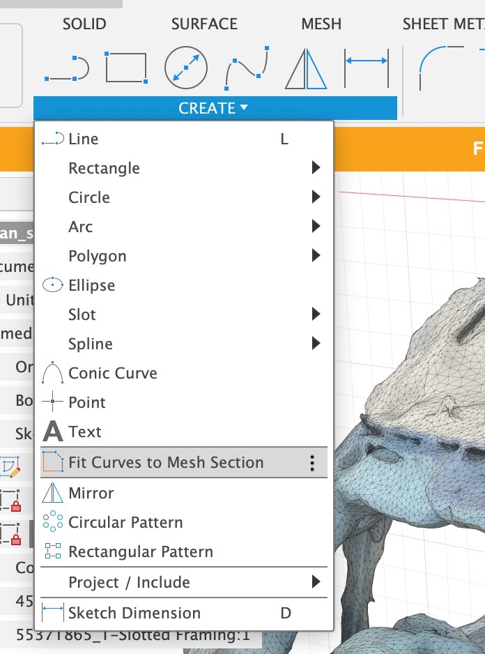
We can now match sketch geometry using Fit Curves to Mesh Selection. This can be found by clicking the Create drop-down in the sketch toolbar.
I used the fit spline tool and selected two points on the orange mesh intersection sketch in the area where I wanted to model a sketch that closely matched the contour of the van panel.
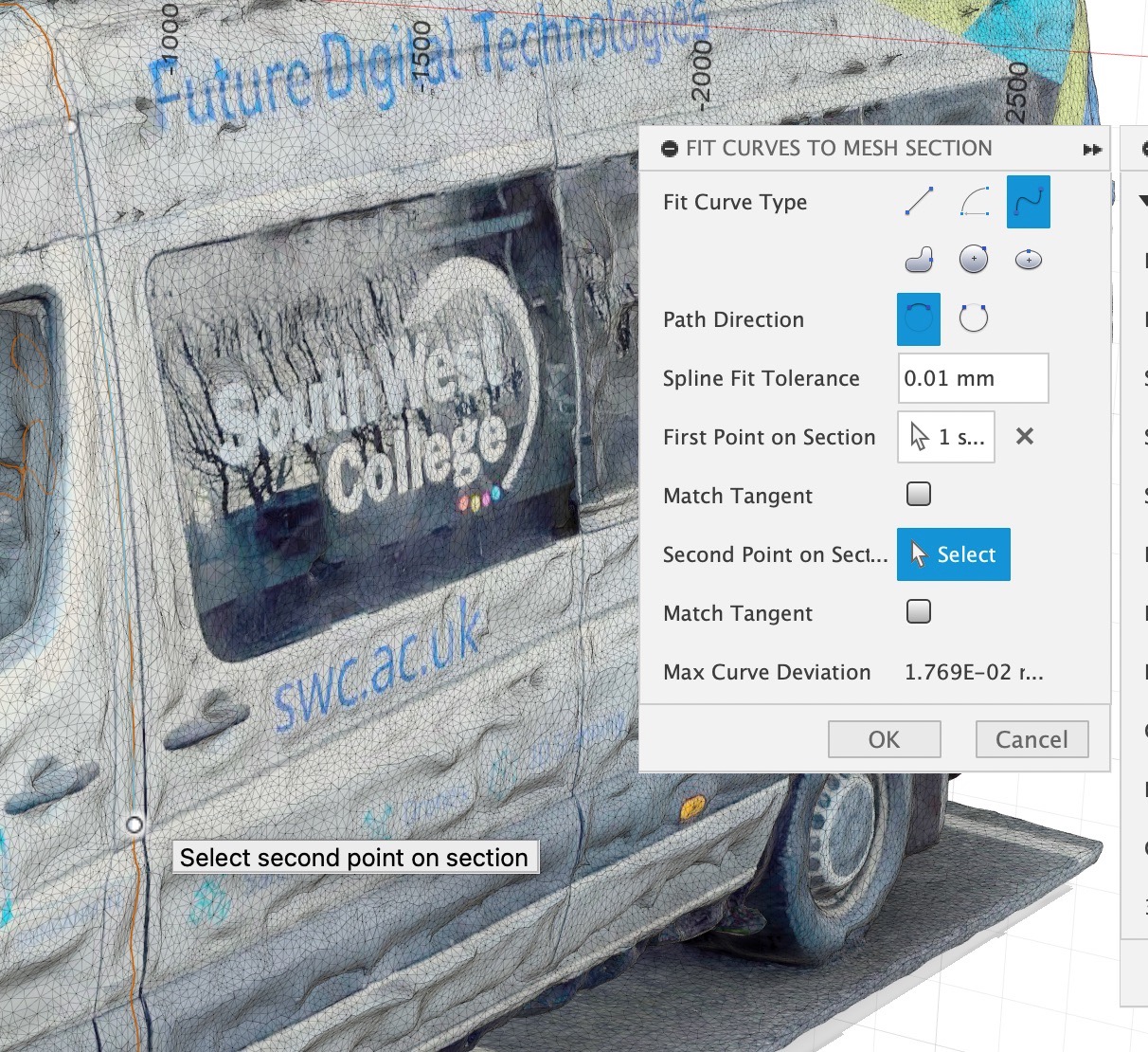
I then used the fit spline tool and selected two points on the orange mesh intersection sketch in the area where I wanted to model a sketch that closely matched the contour of the van panel.
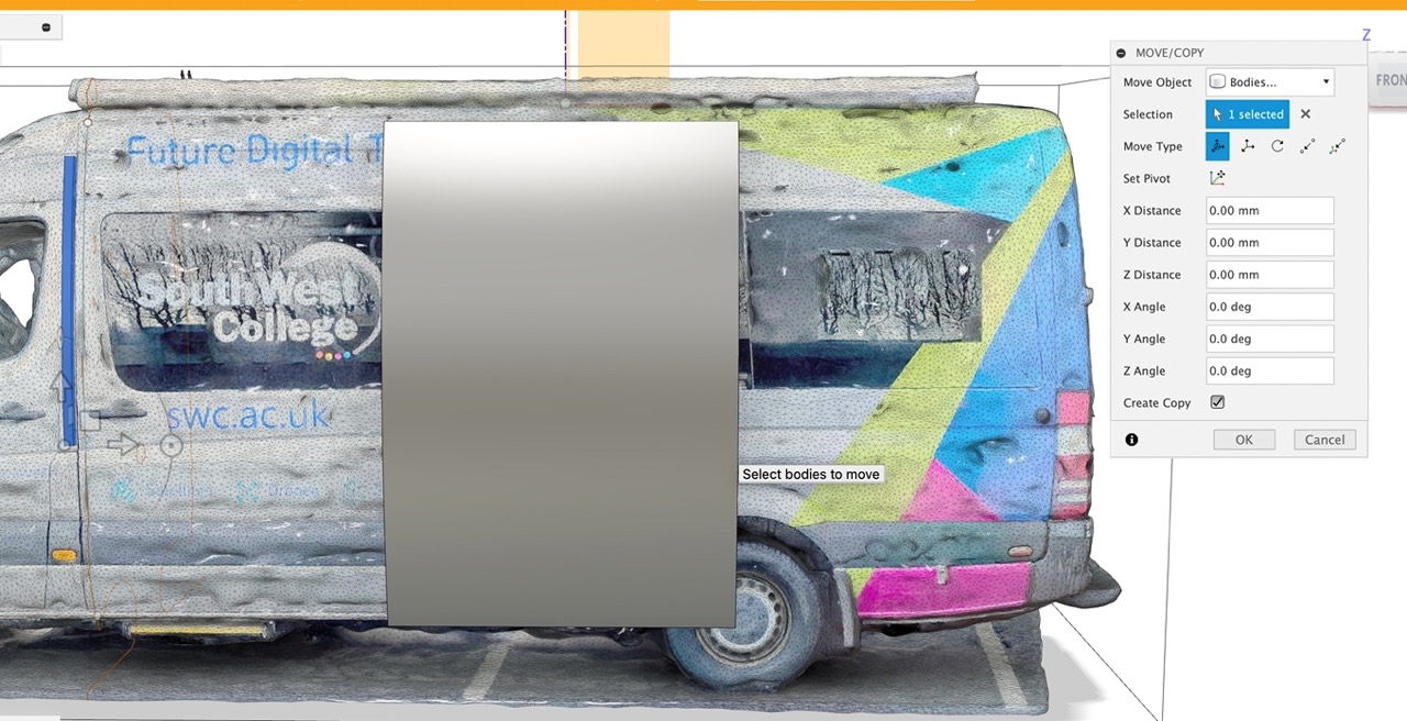
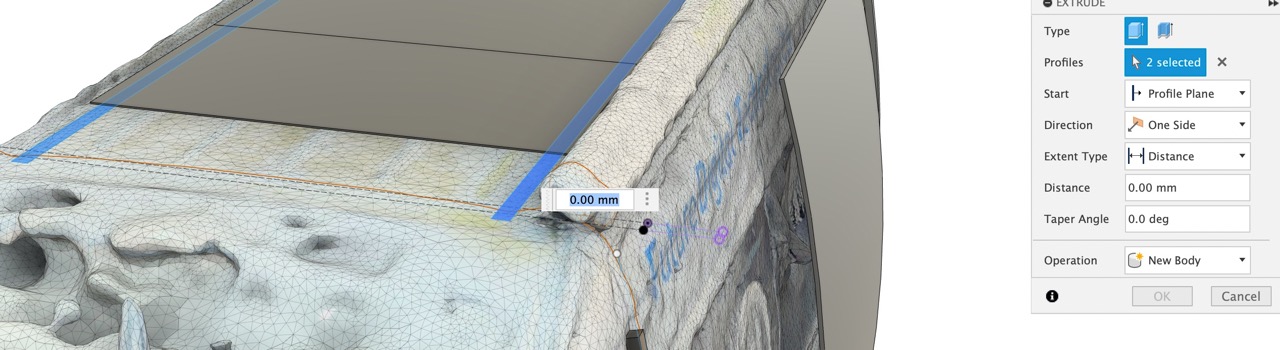
i extruded the a surface to the size of the door, this is to simulate the door in the open position where it sits out from the van body.
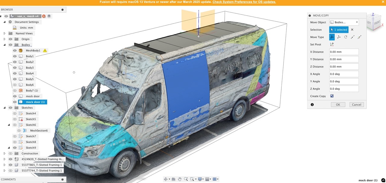
when wextruded in copy and move the door to its open position using the move/copy command.
I eyeballed some solar panel frames to the approximate size of the van roof
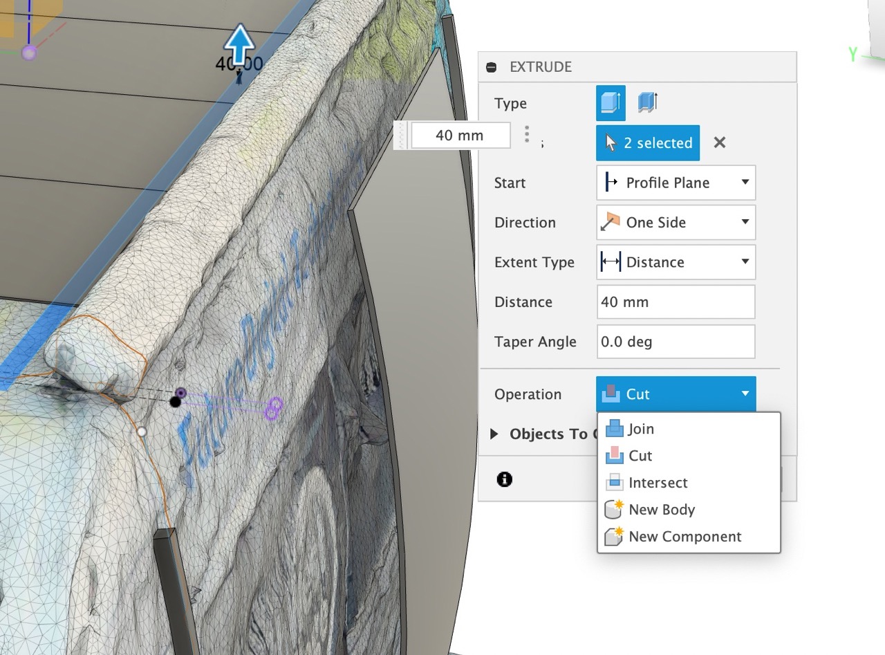
I then make a frame for the solar panels extruding a sketch that will maximise the space on the roof
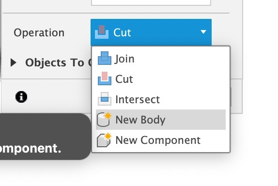
when extruding I extrude the part as an new body under the operation type.
I then created an upper frame to hold the upper layer of panels that could move down to form an awning and double the solar panel coverage when static.
I added rails on the side of the van wall to hold the mechanism to move the upper panel down when the van is stationary.
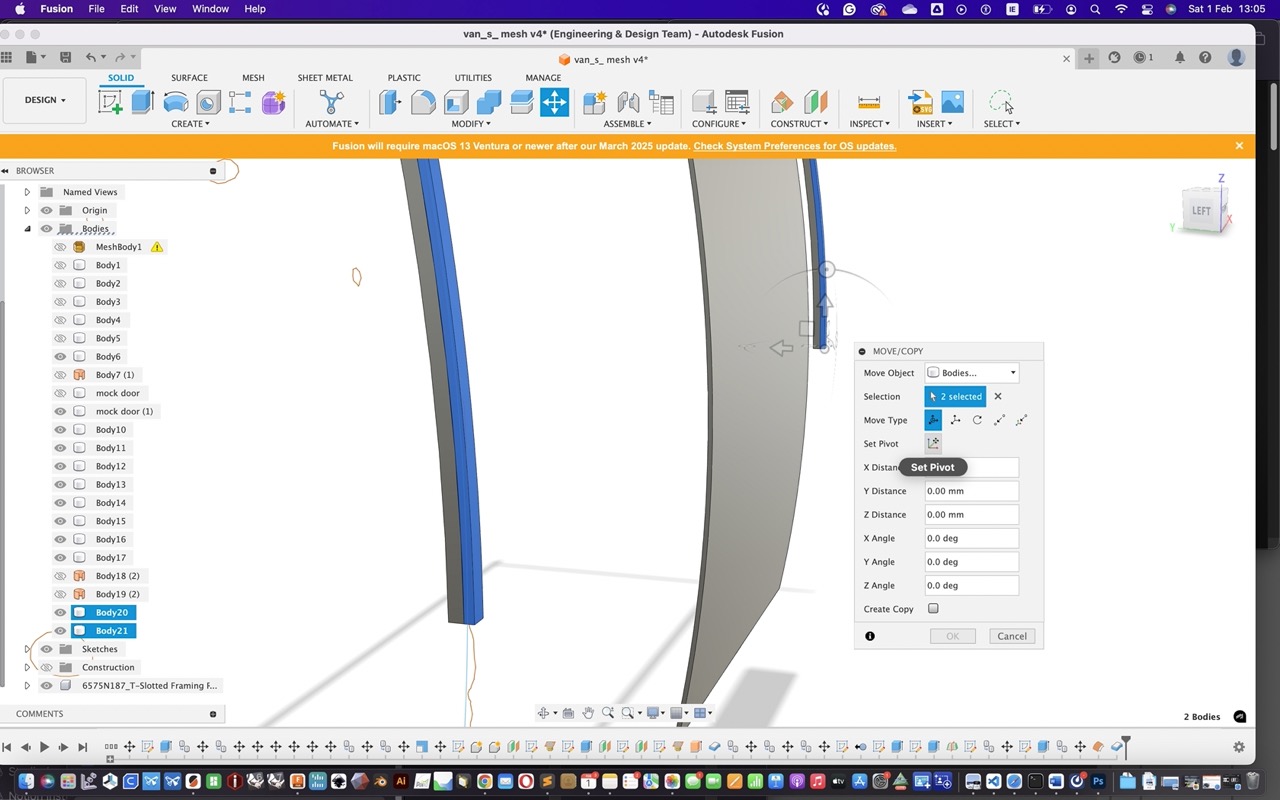
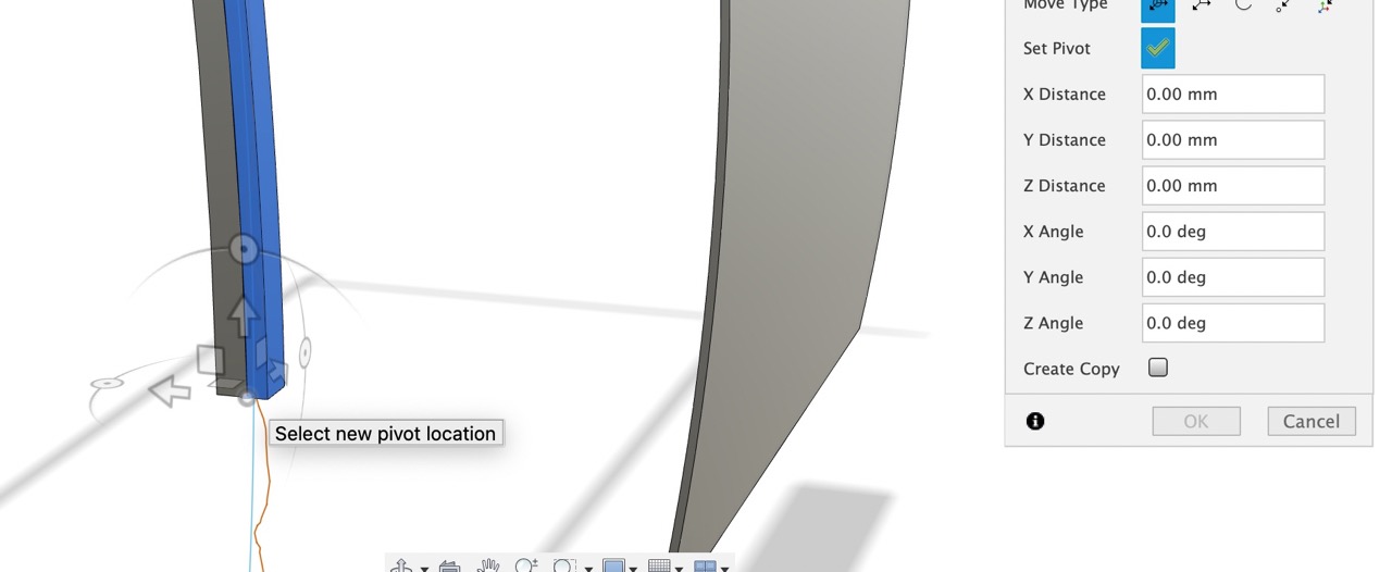
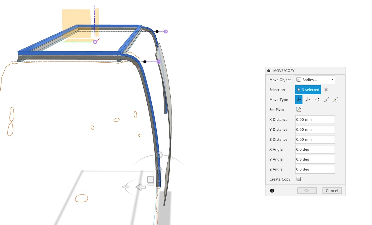
I use the move/copy command to manoeuvre the mechanism to its open position. I need to set the pivot to where the hinge location will be.
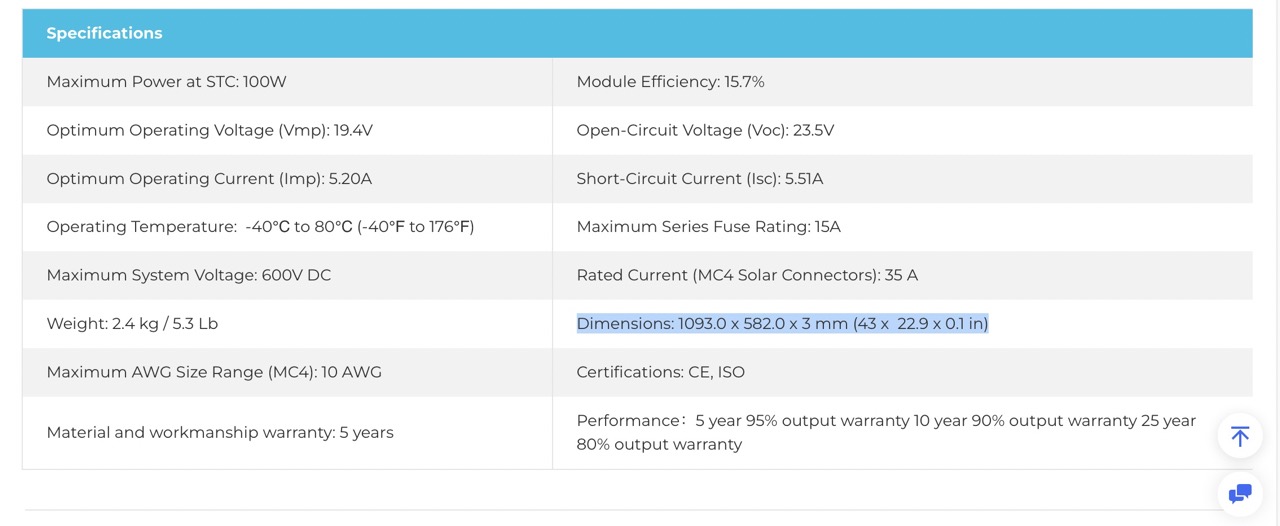
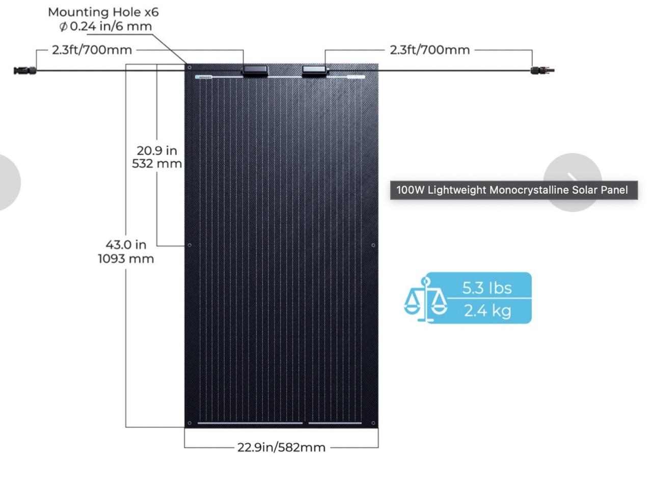
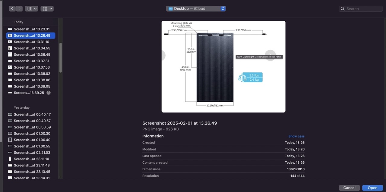
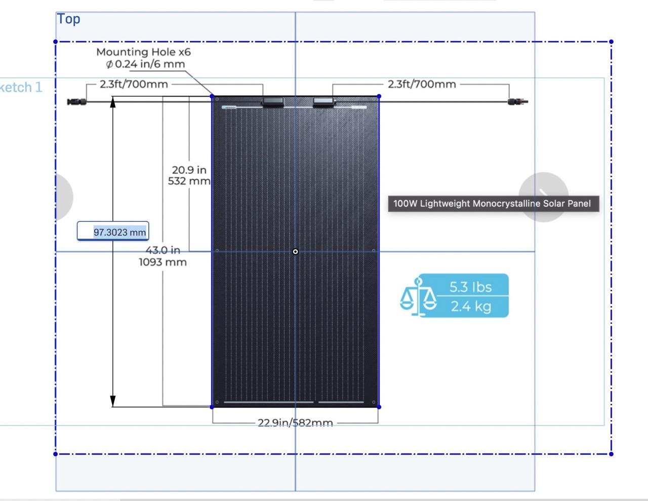
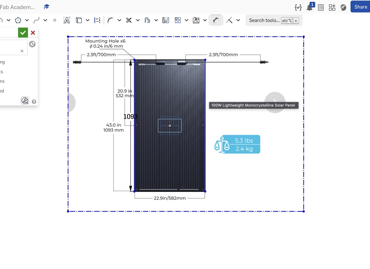
At this point, I identified potential solar panels that would fit the frame and meet the technical specifications required. The panel identified below, on initial inspection, seemed to meet the requirements in terms of dimensions and weight. I took a screenshot of the plan view image with dimensions. I would be able to bring this into the CAD package to trace the panel and to model it in CAD accurately.
Onshape
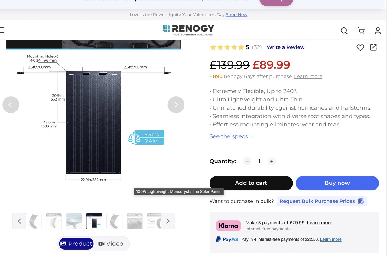
I decided to use Onshape to model the solar panels. I identified lightweight panels that would be suitable for the van. These were identified using a very quick internet search; it is possible better and more efficient panels might be better. But for now, we will work with these. I took some screenshots and below are the steps taken to model the part.
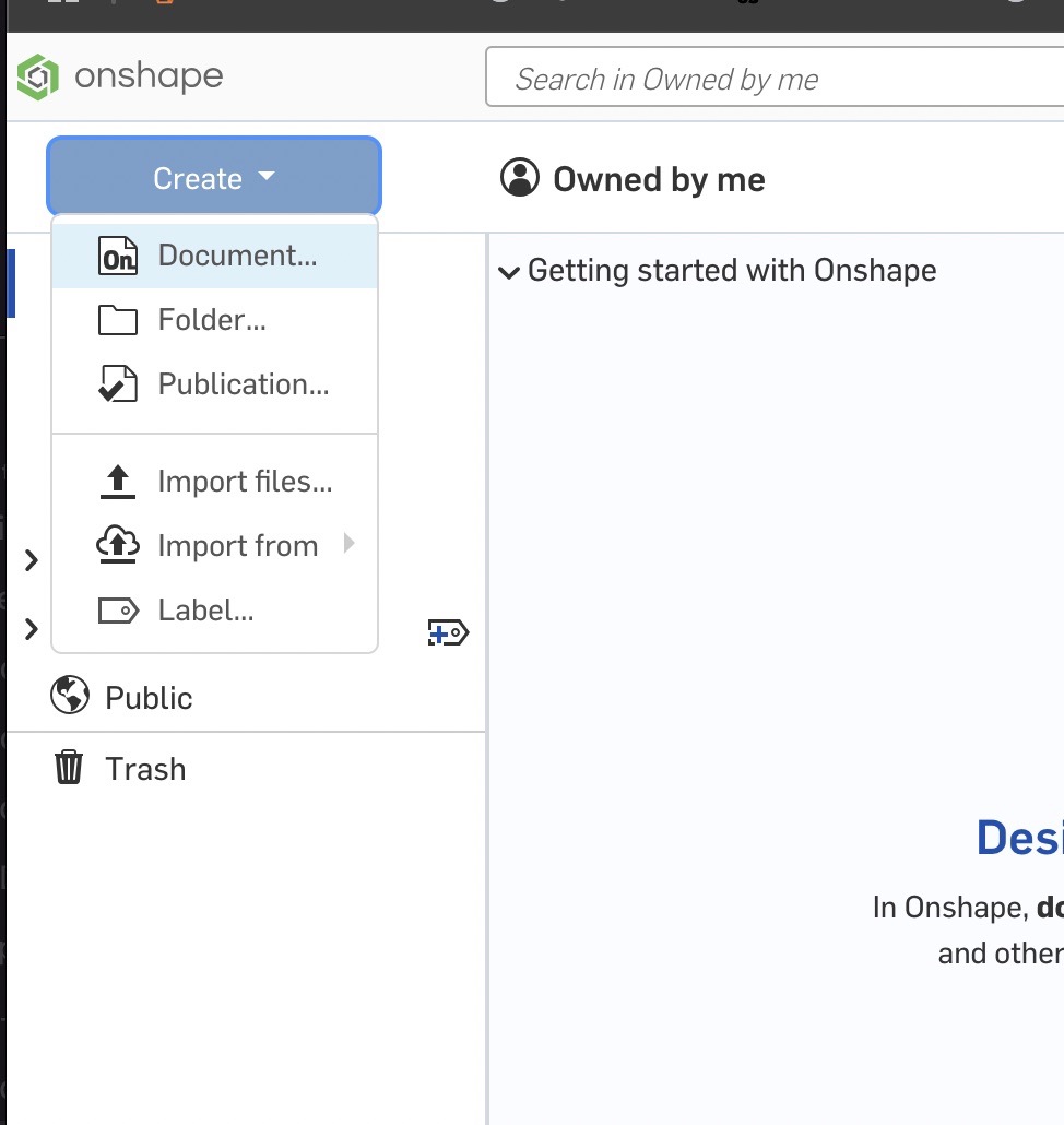
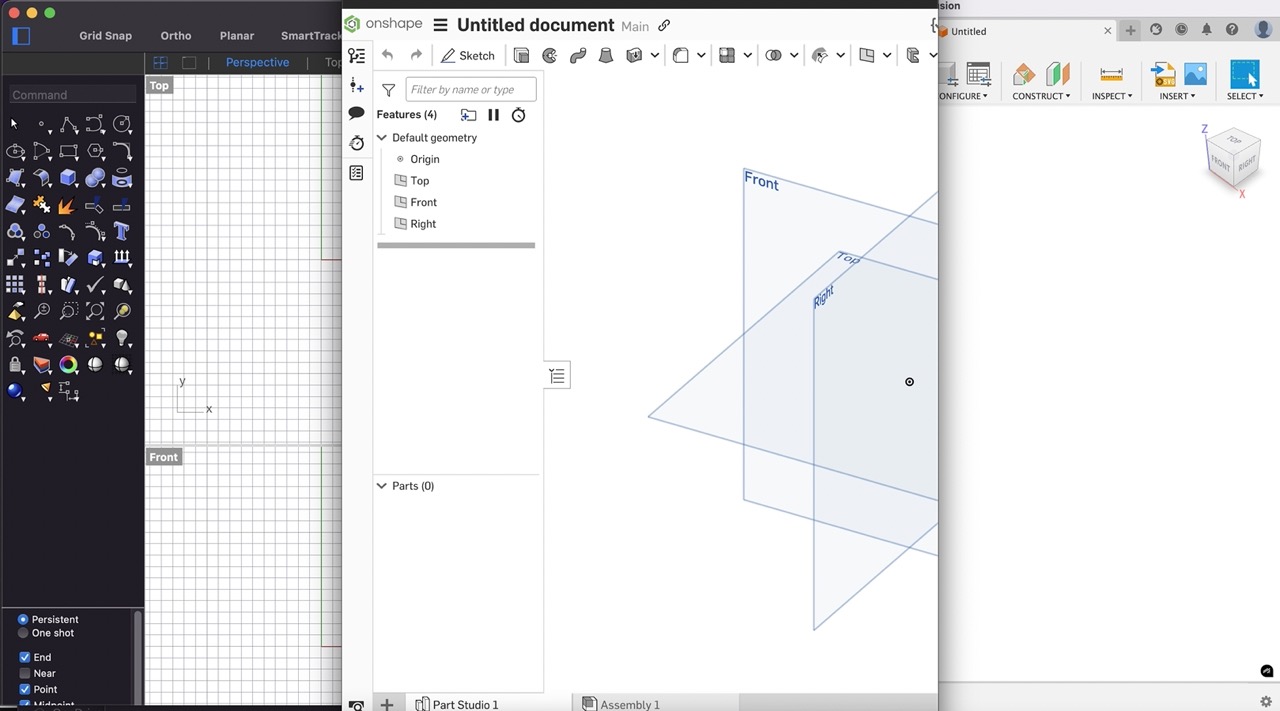
I started by logging into Onshape and creating a new document.
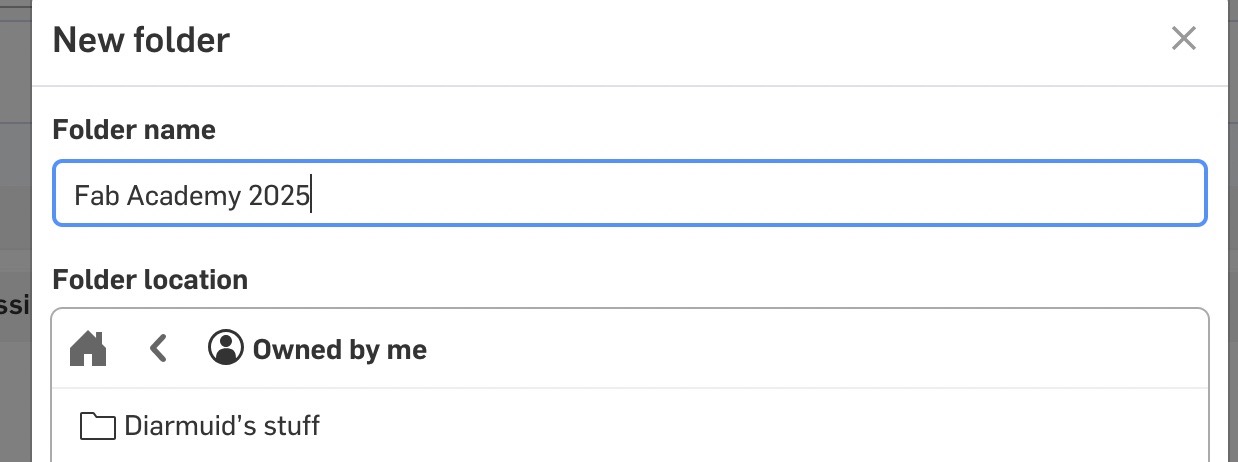
I then created a new folder called Fab Academy 2025 to keep the files organised.
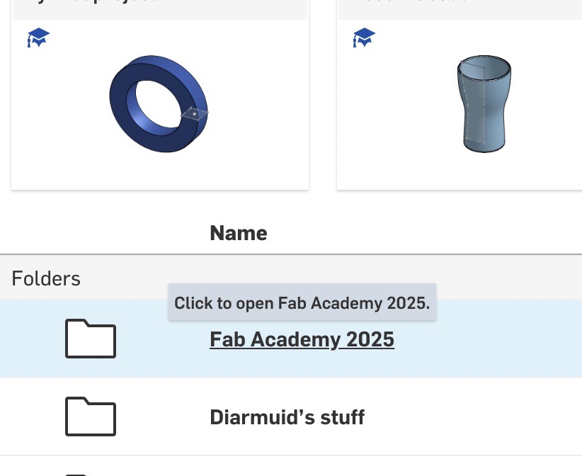
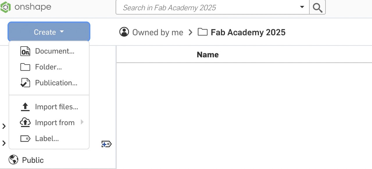
Once created, I opened the new document called Solar Panel.
I then created a new sketch on the xy plane.
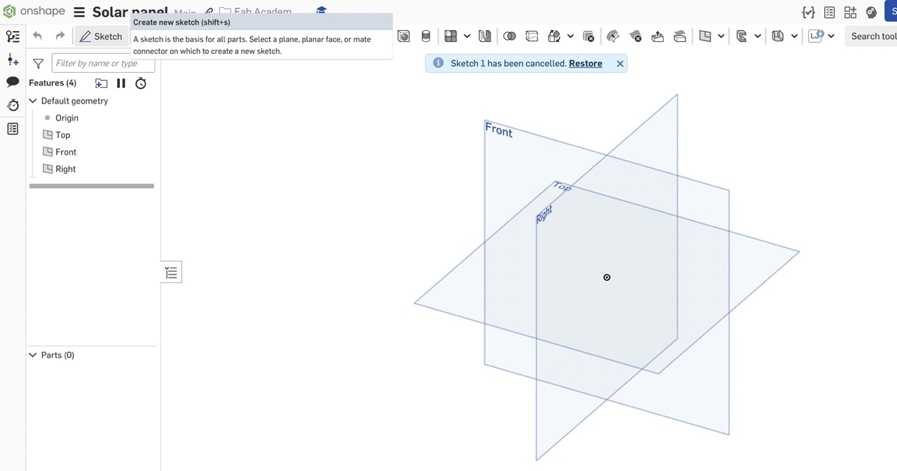
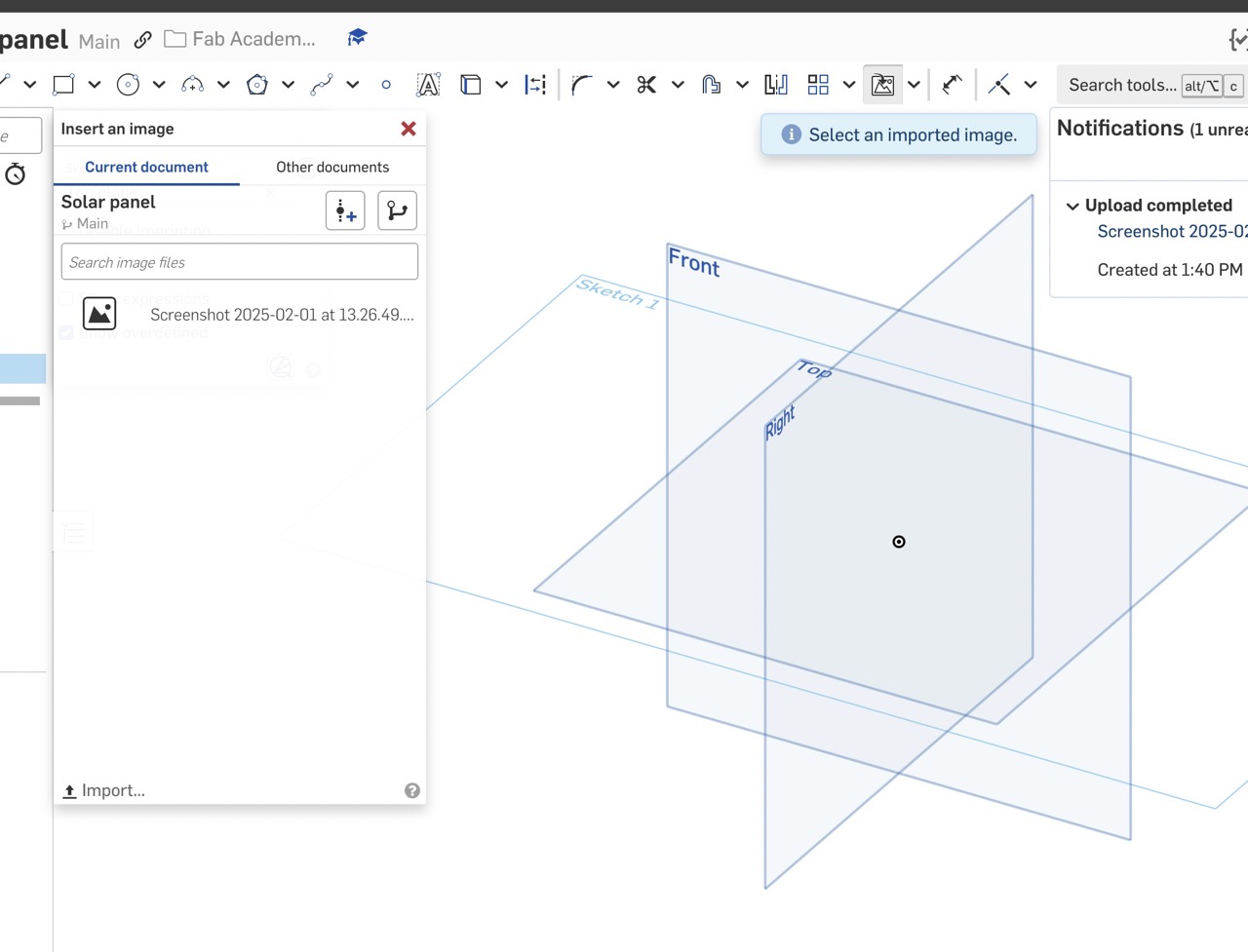
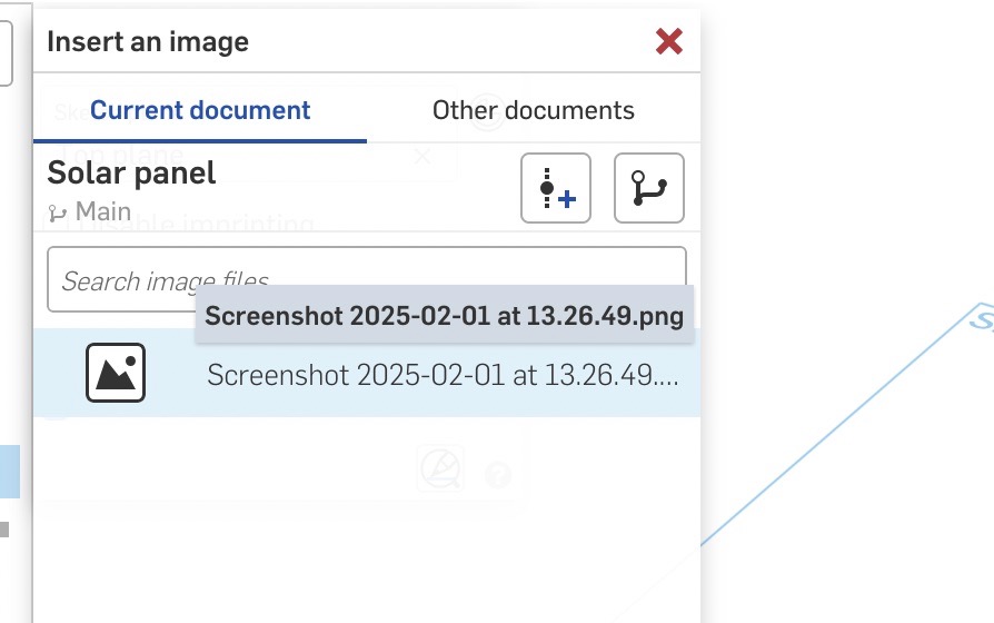
Once in the sketch I import an image of the screenshot of the panel.
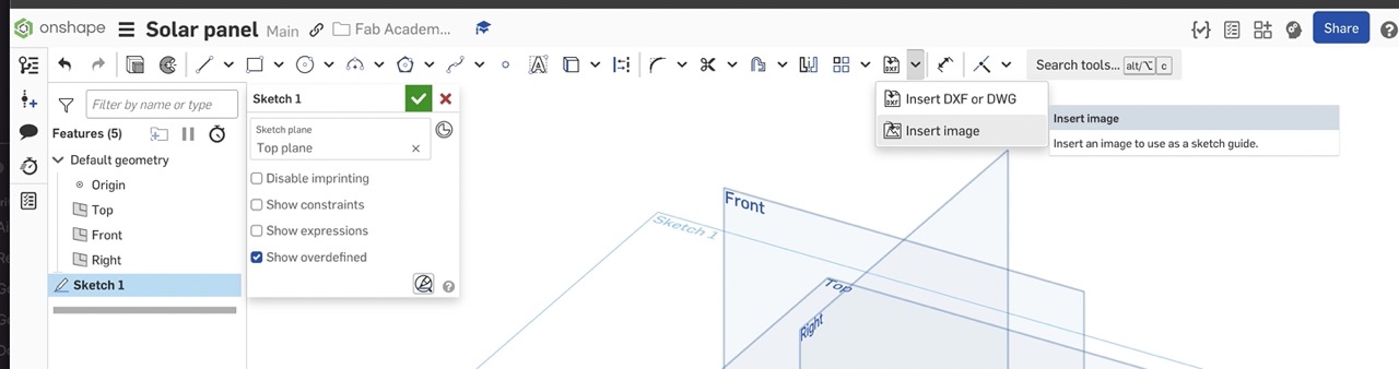
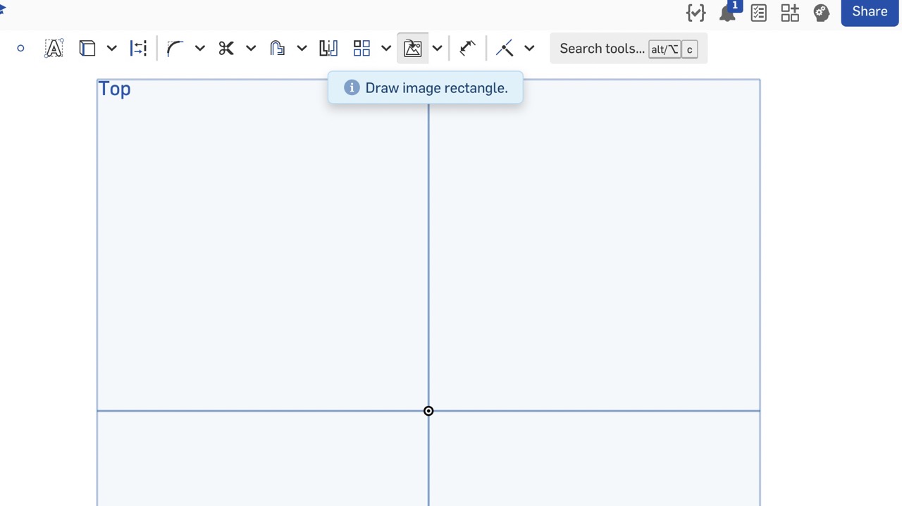
This needs to be inserted into the sketch as shown
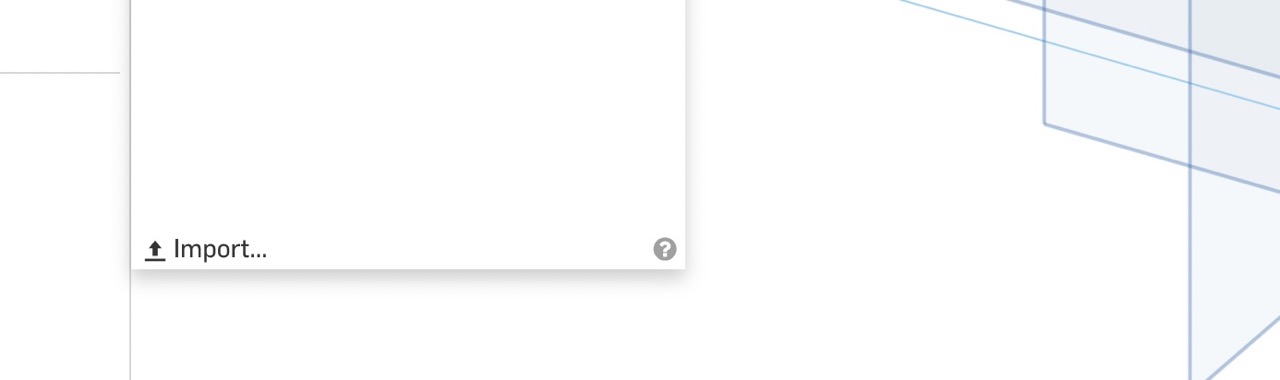
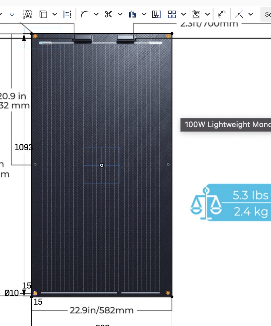
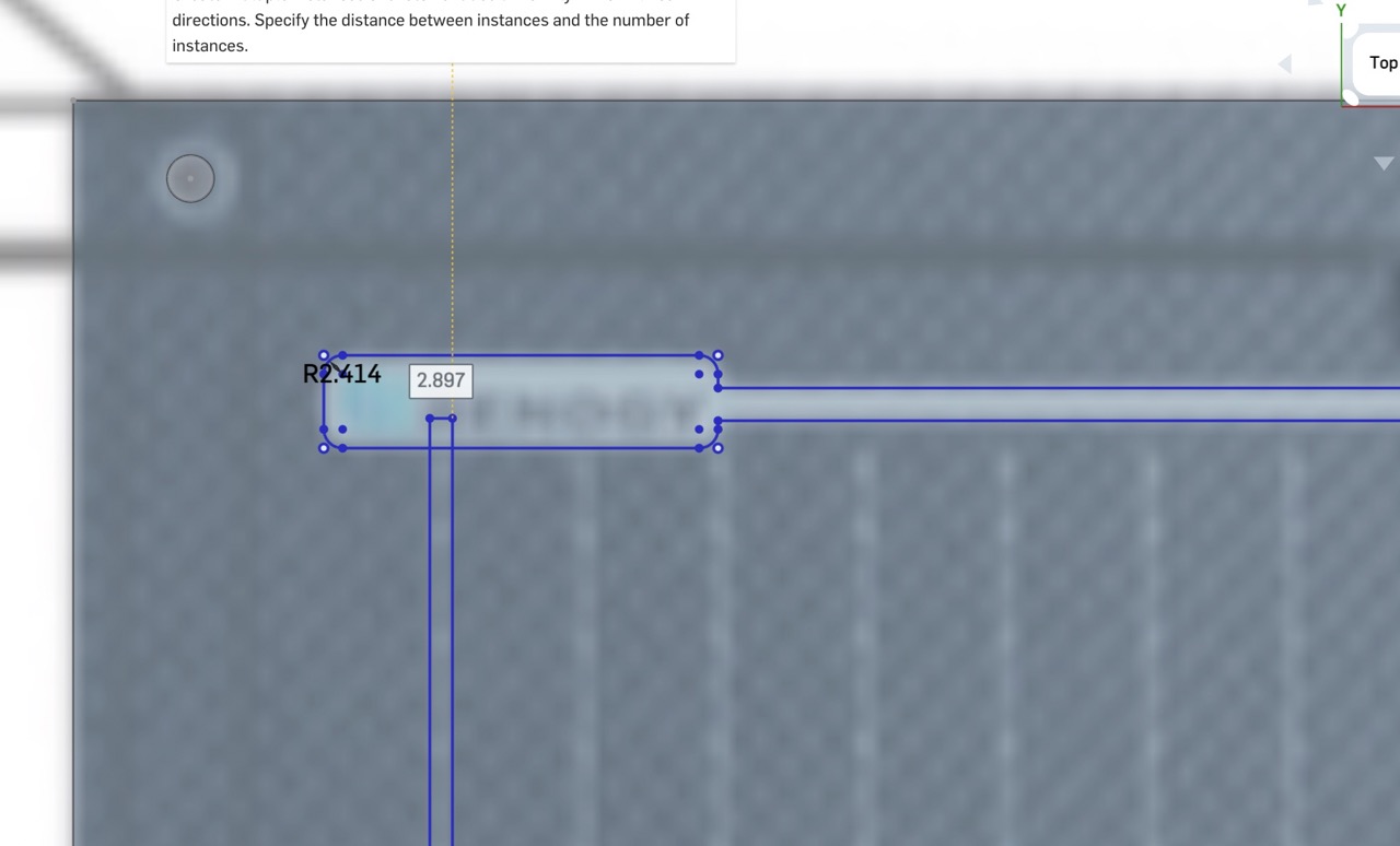
I then scale the image using the dimension tools to match the dimensions in the sketch.
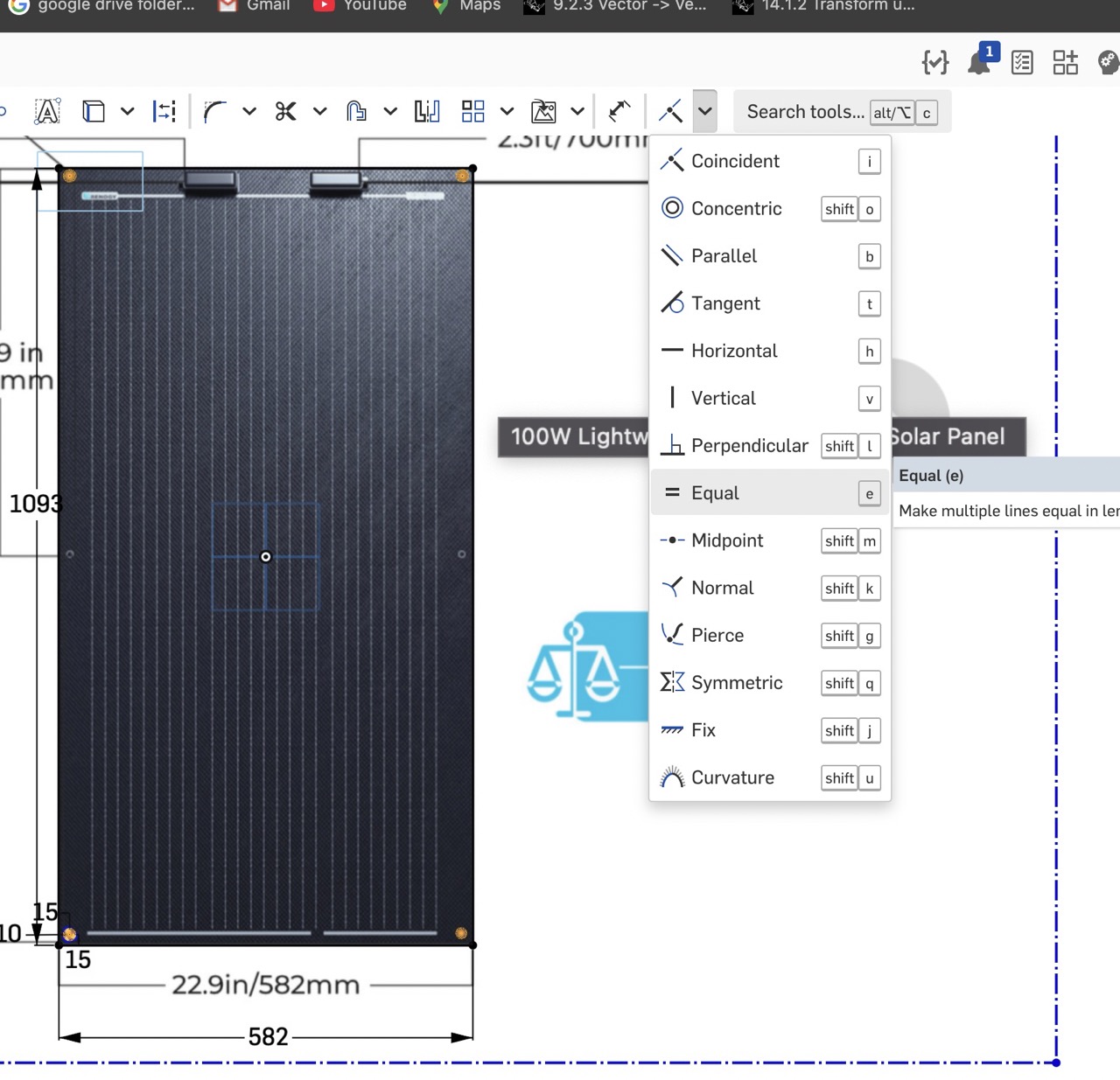
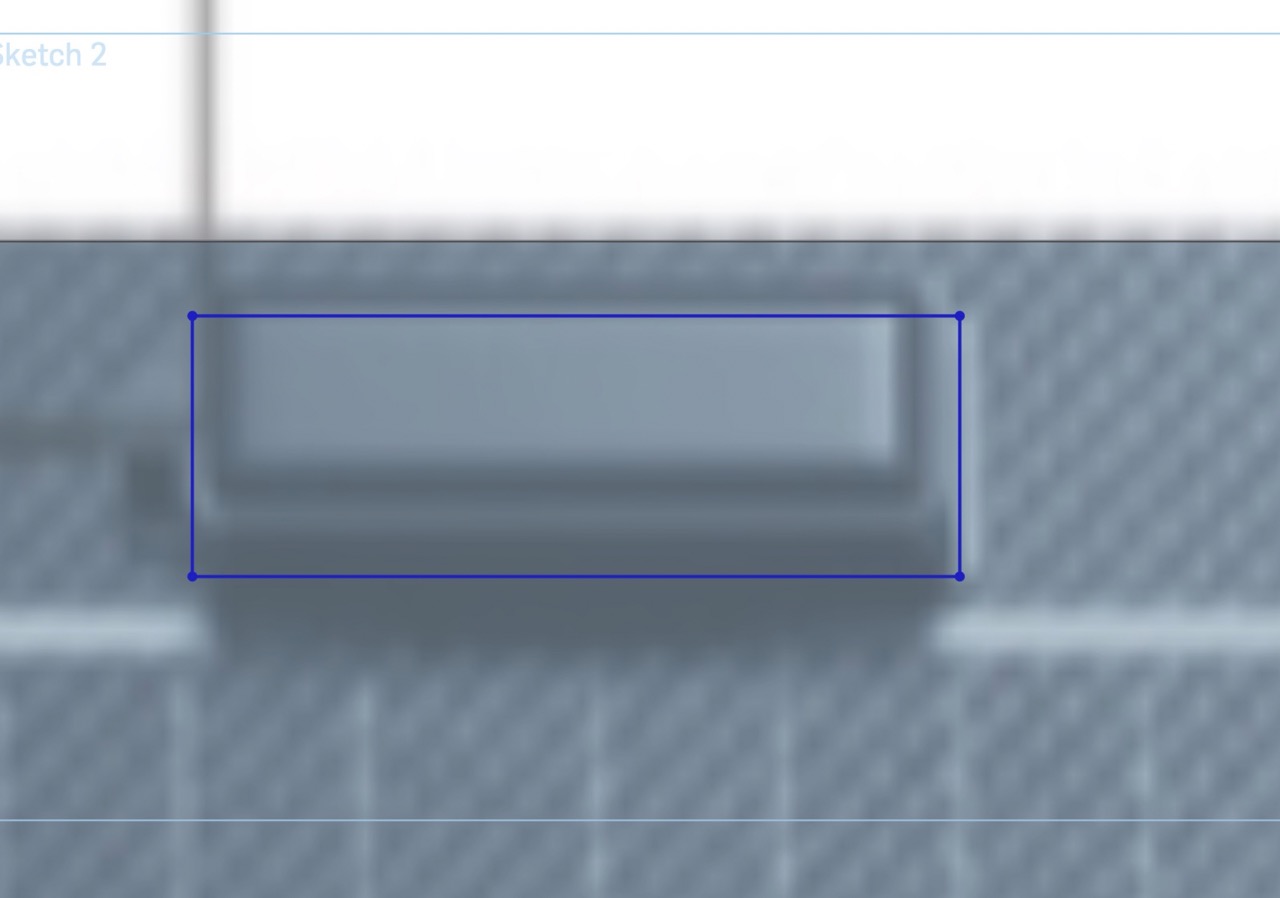
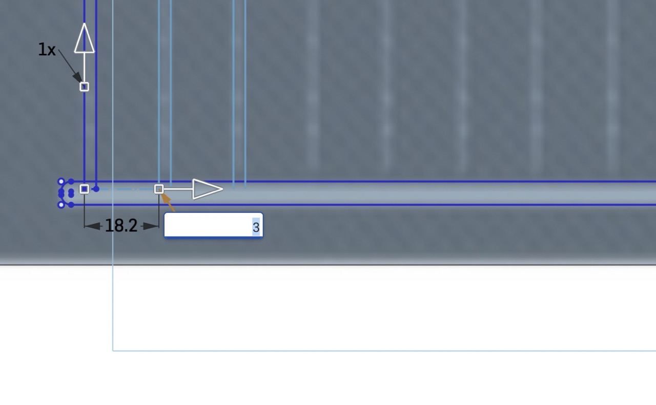
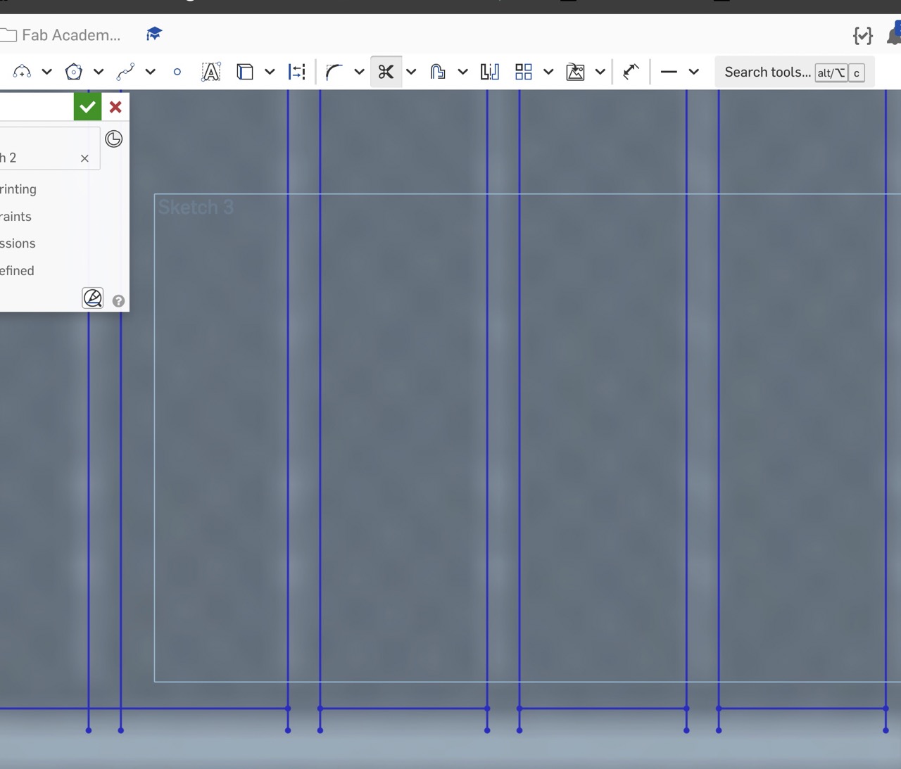
I proceed to trace the detail of the panels that can be used to extrude the panels.
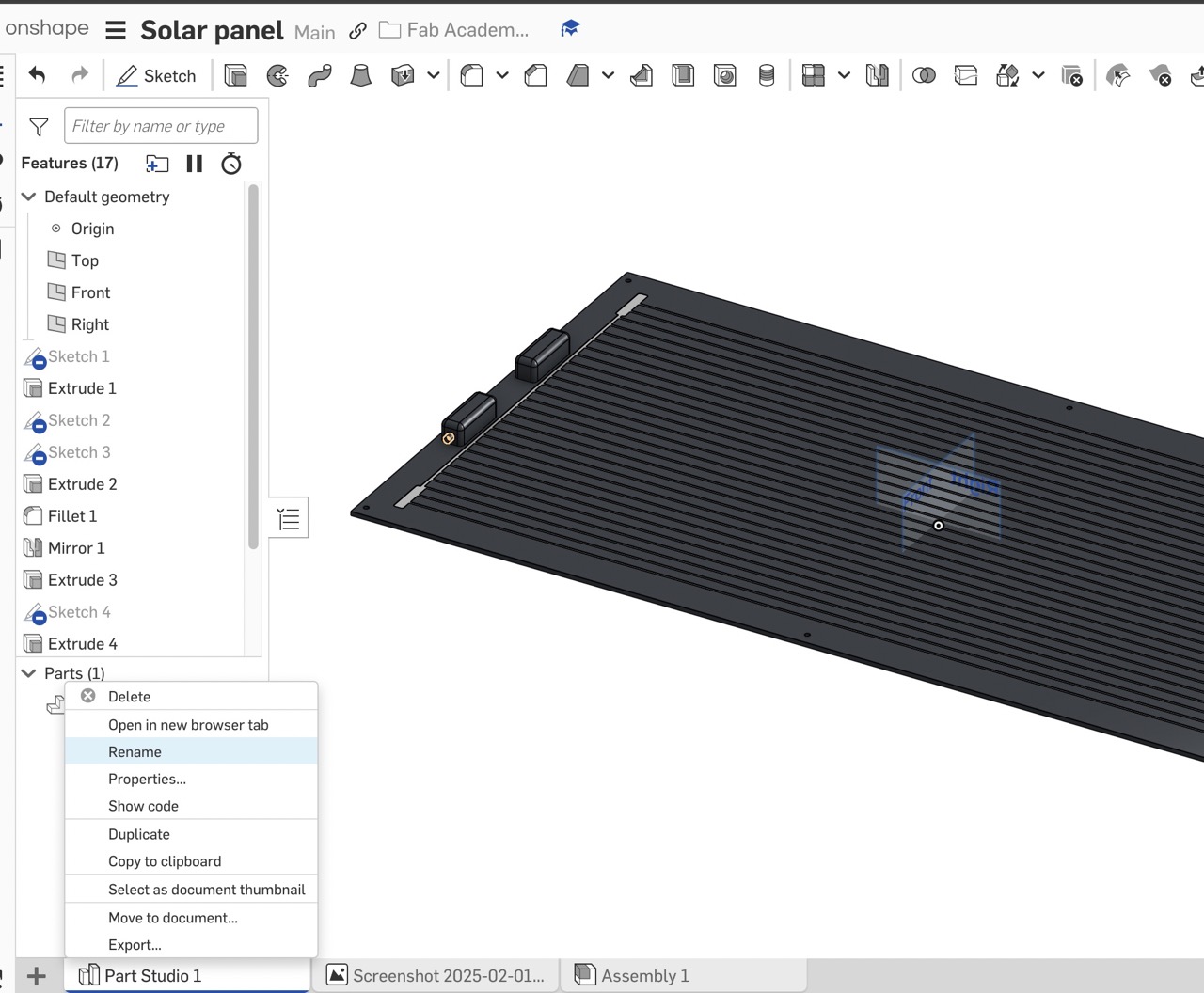
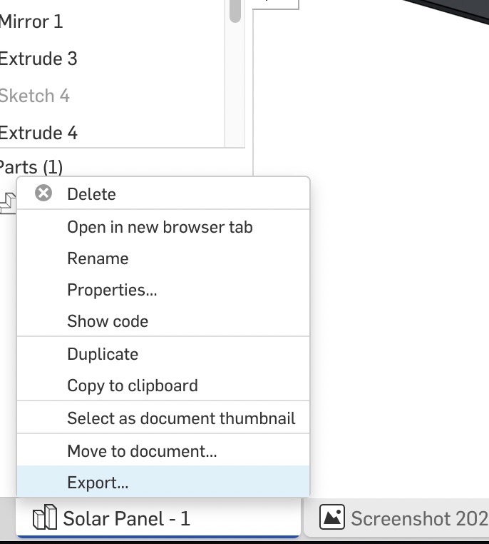
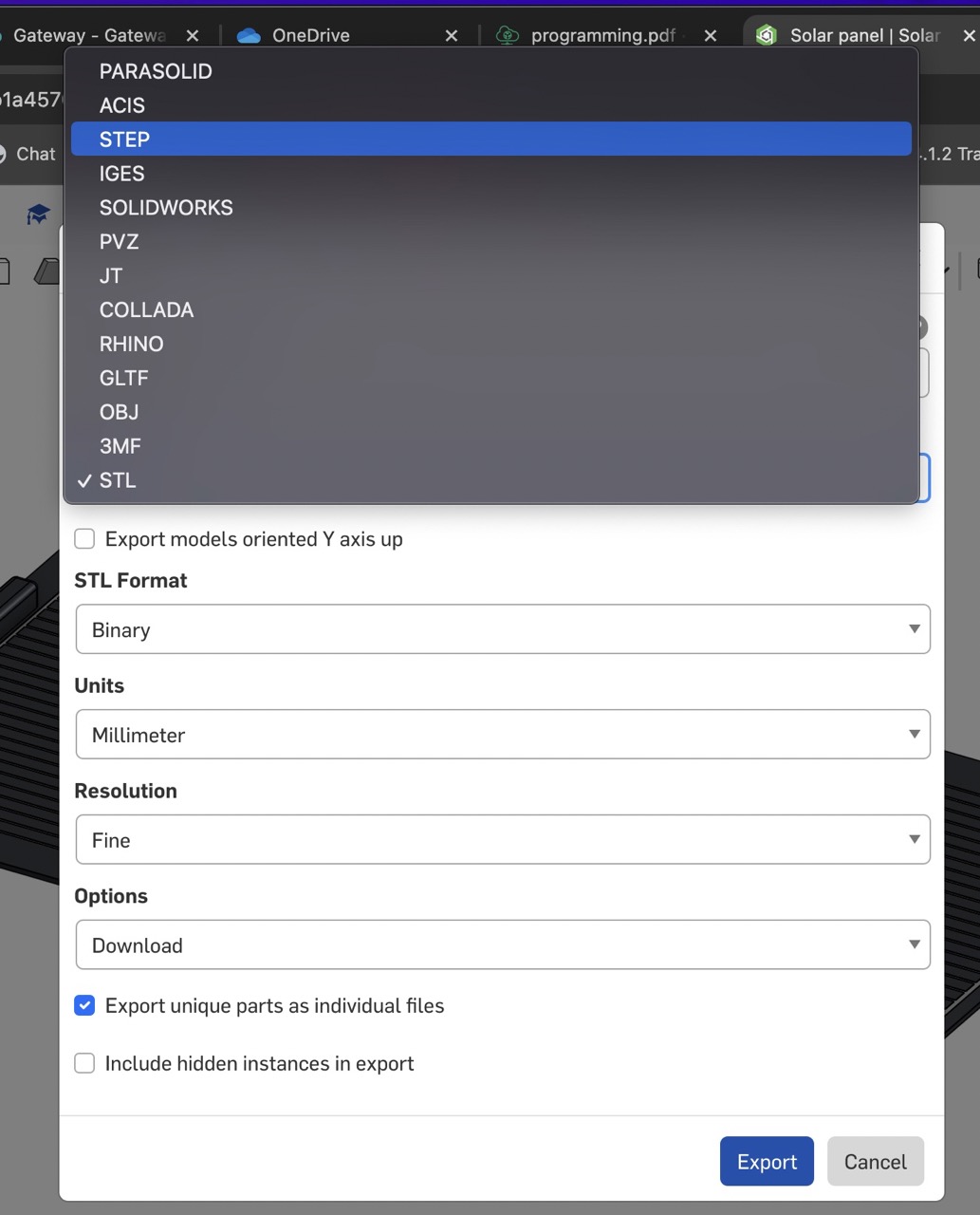
I export the solar panel as a STEP file and save it to my computer.
This is then uploaded into Autodesk Fusion into the relevant project folder.
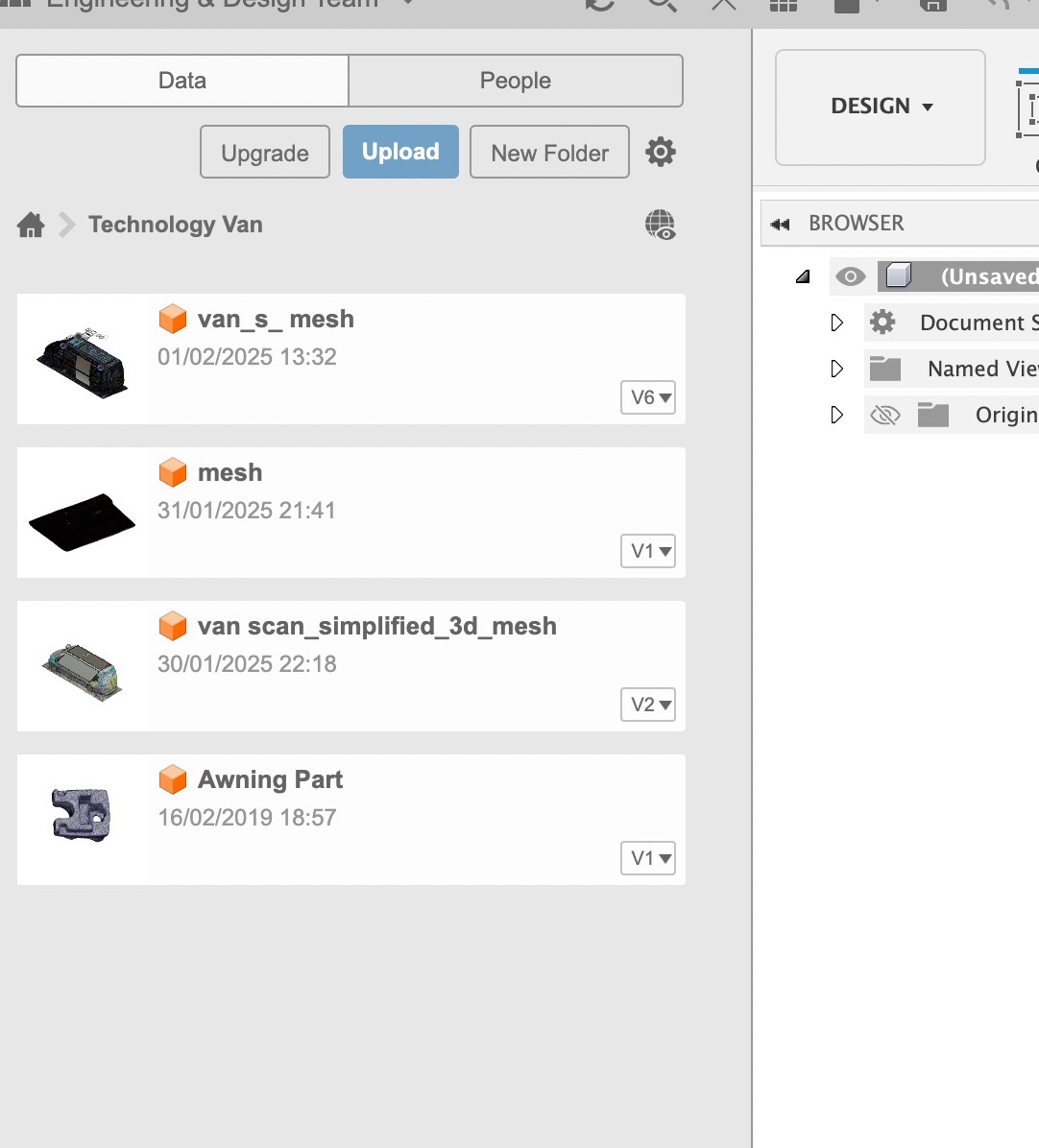
Once uploaded with the correct design file open and active in Fusion, right-click on the solar panel file in the browser window and insert into current design.
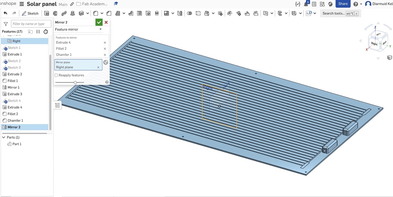
The panel can now be moved into position. You can copy and paste the component or use the pattern feature.
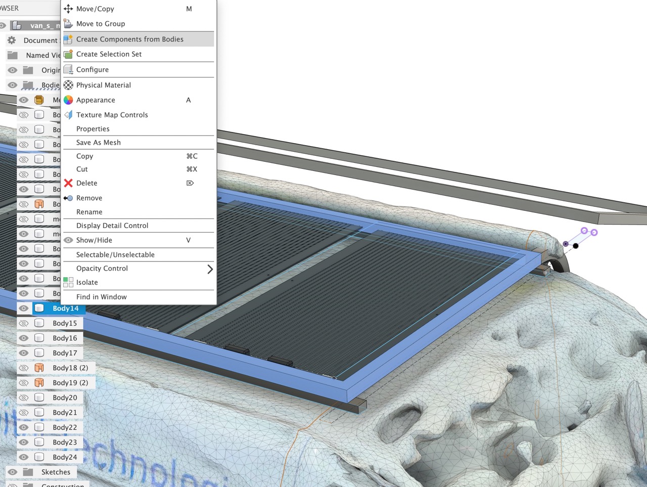
I also create components from the frame body so that joints can be created for them and the assembly can be animated.
Rhino and Grasshopper
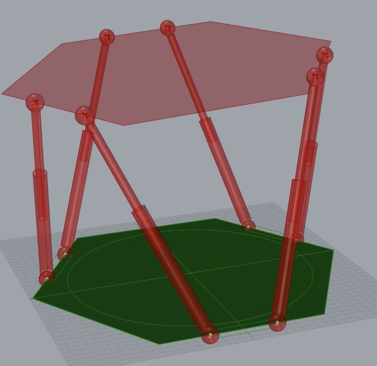
I decided to model a simple hexapod using Grasshopper, a plugin for Rhino - this was for one of my other final project ideas.
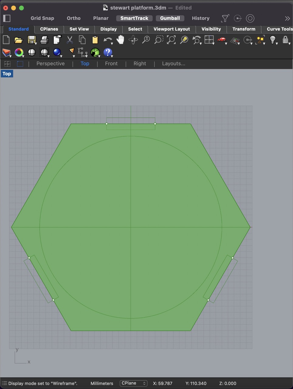
I start by creating a polygon in Rhino the size of the base plate. I also mark where the base points for the linear actuators are.
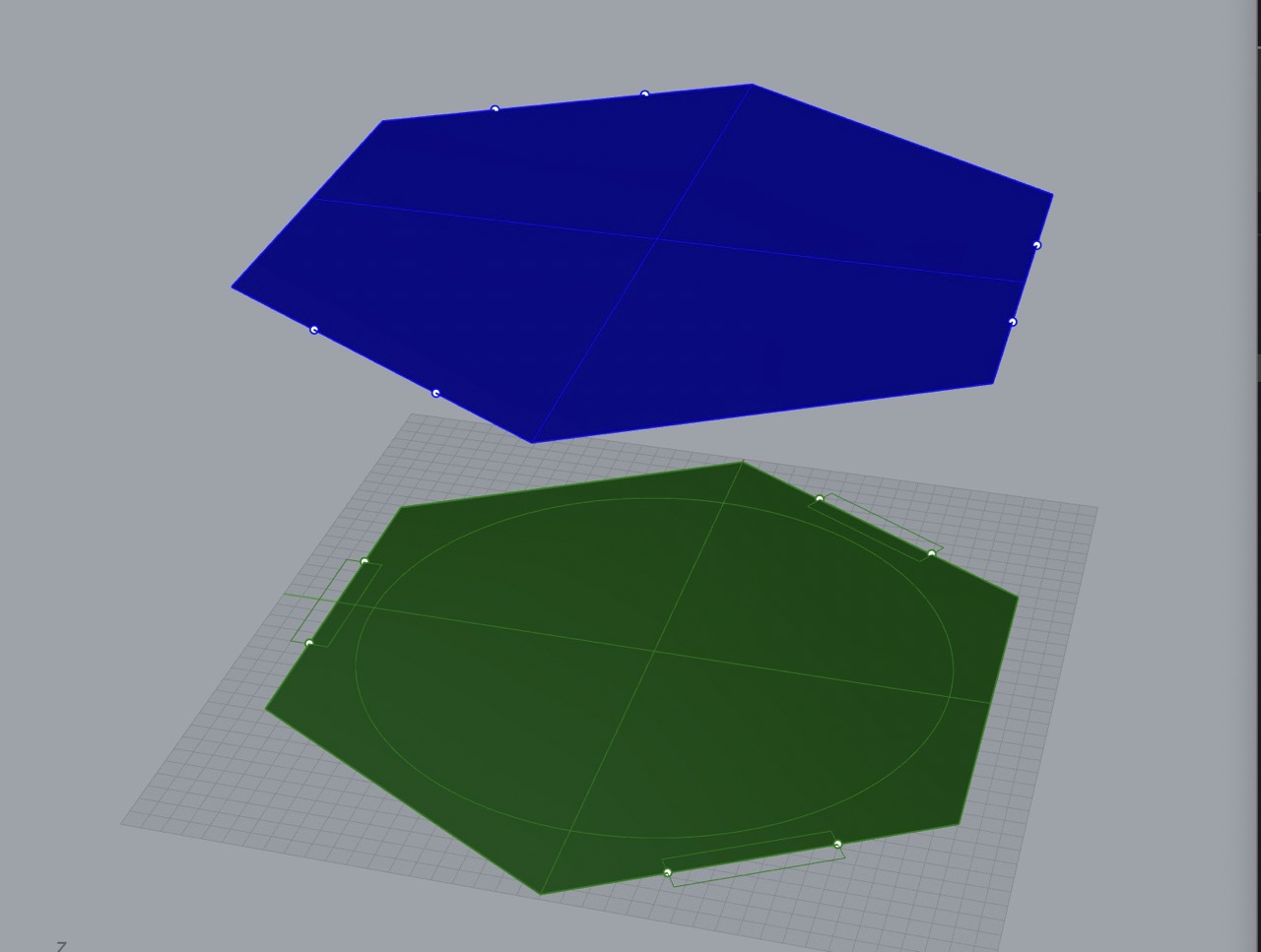
This polygon and 6x points are copied to another layer, moved up in the Z axis the distance wanted between the base plate and top plate. I also rotate the top plate by 120 degrees.
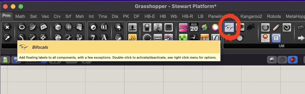
I use Bifocals in the definition; this names each component that I use in Grasshopper and is good for beginners to be able to read what each component is.
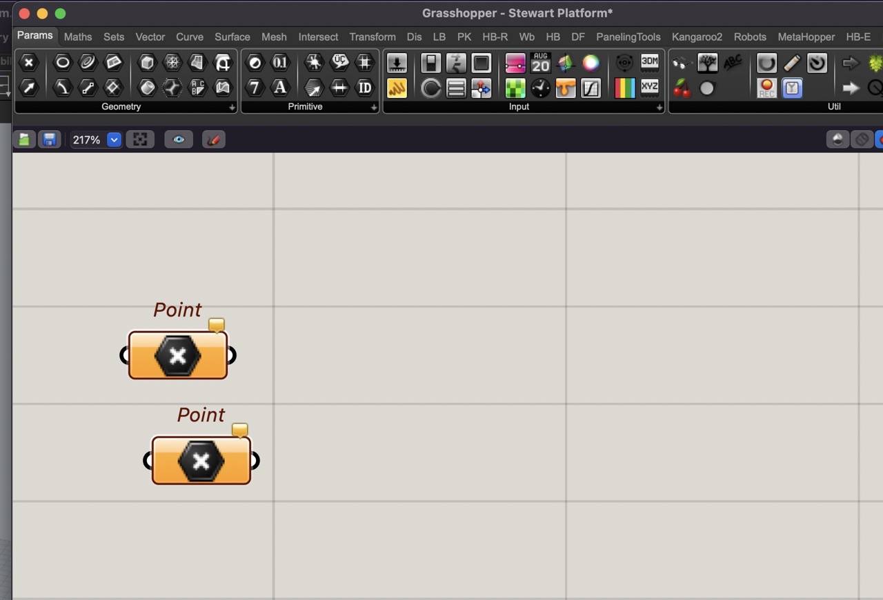
I add two point component to the cannvas, these can be dragged on from the menu bar from the params tab
Right-click on the point component and select set multiple points - when selecting multiple points you need to select them in a logical order.
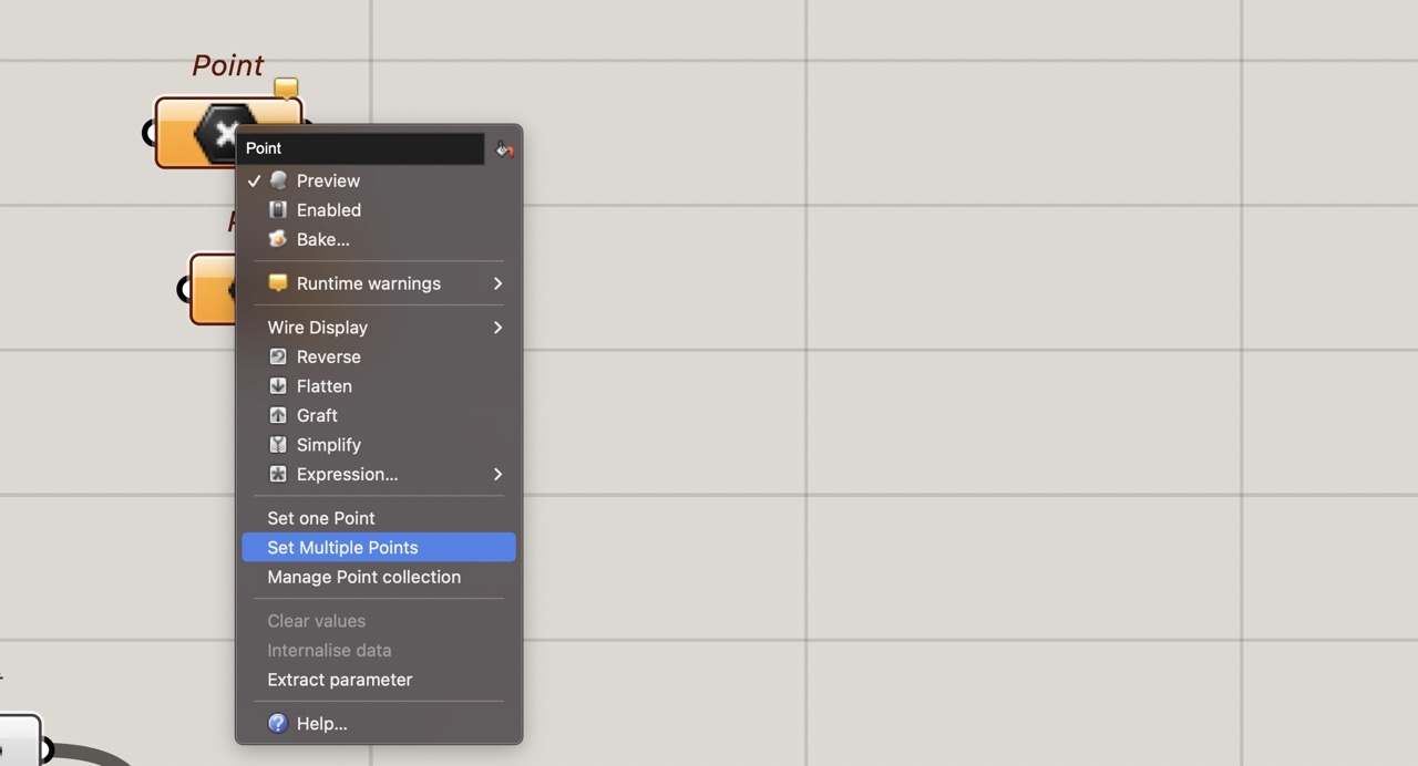
Do the same for the points at the top plate - again in a logical order - the first point selected will end up being joined to the first point in the previous selection.
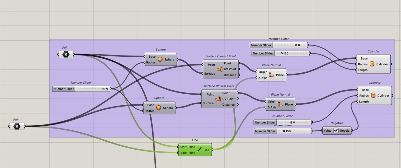
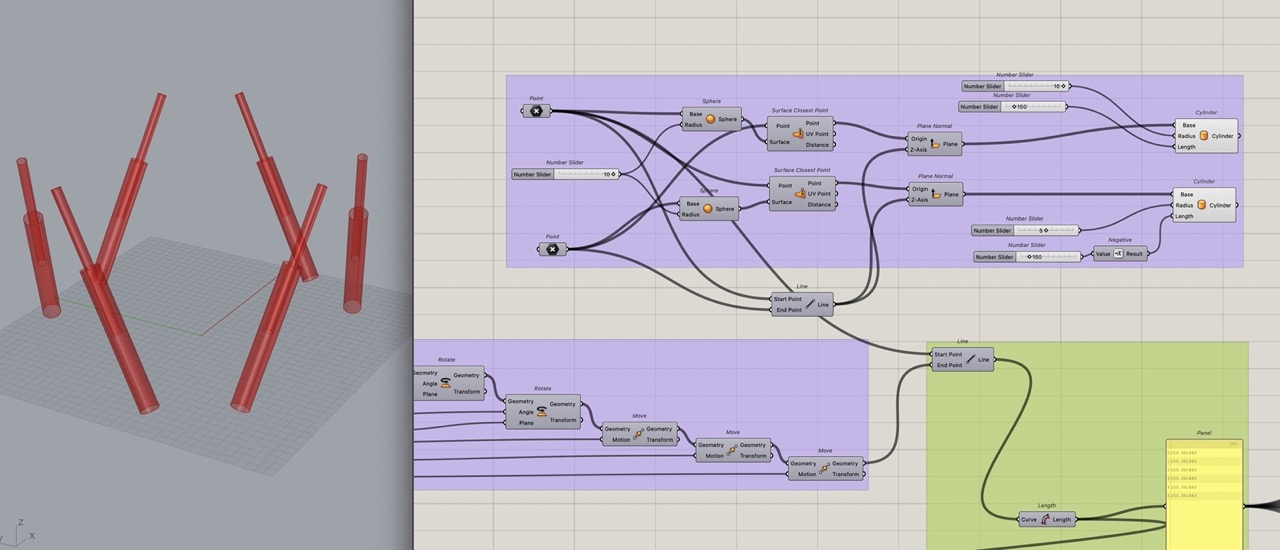
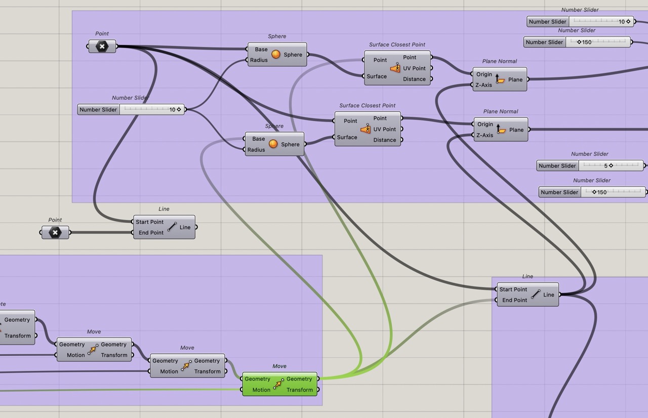
We will now create spheres around the base points. These will eventually be connected to the top points; however, we will first need to do some translations with the top points - this will drive the length of the linear actuators. We will not actually be moving the linear actuators, rather moving the top plate with pitch, roll, yaw and X,Y,Z to the position we want it at.
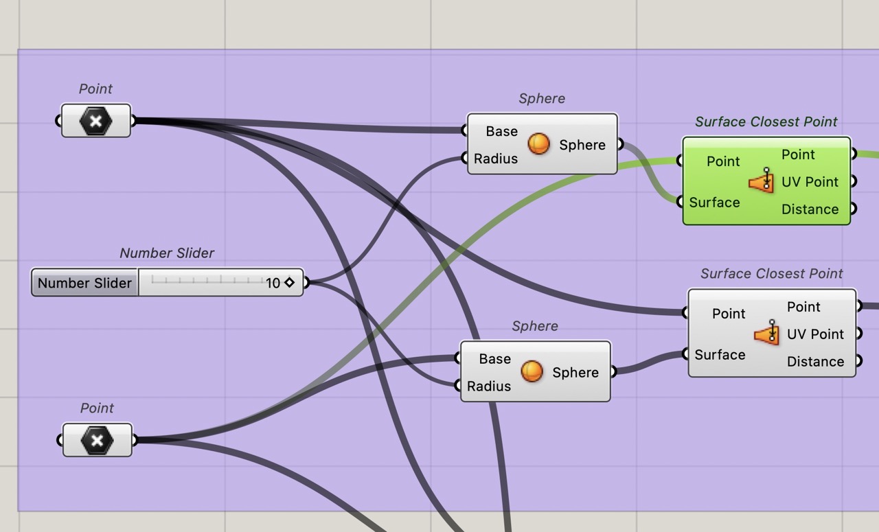
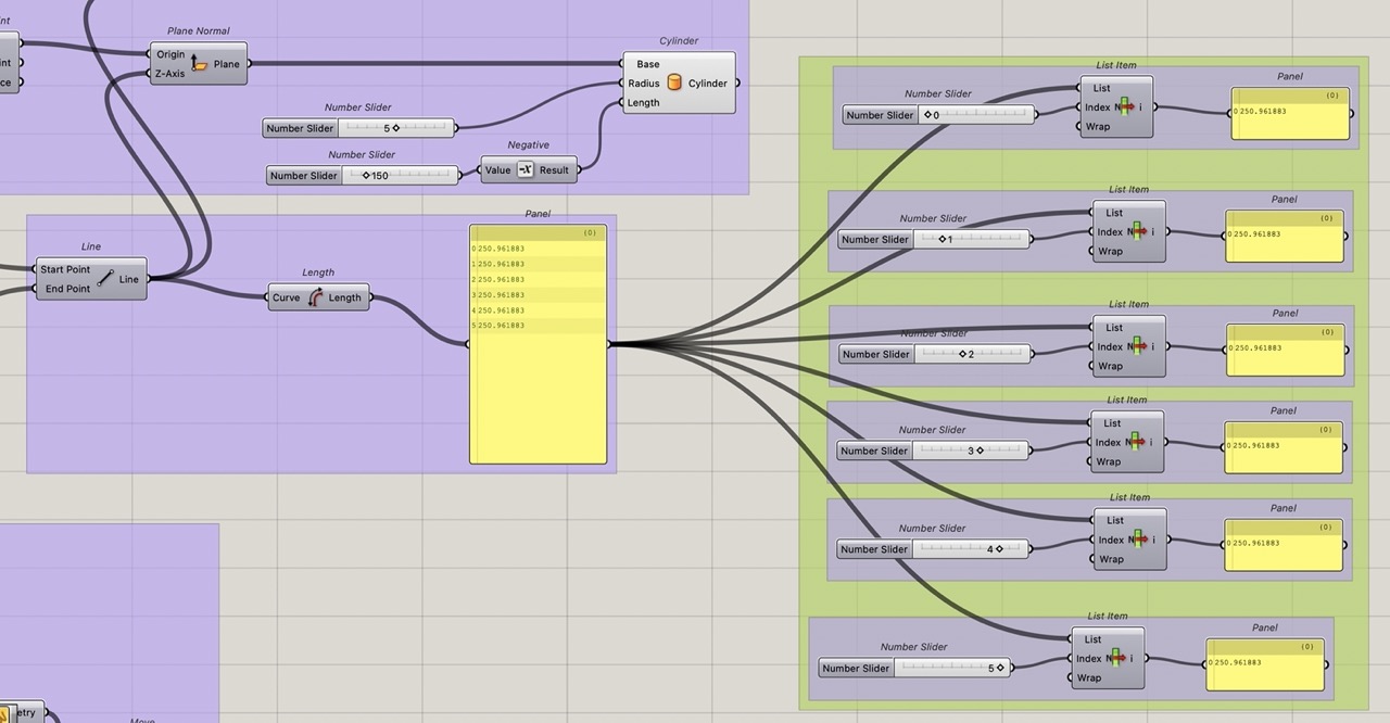
In order to achieve this we will first create a line between the two spheres by finding the closest point between the two spheres, creating a line and putting a plane on this line with the Z axis along this line. We can then create a cylinder to the diameter and length required.
I'm using this process as it will update when we move sliders for pitch, roll, yaw and X,Y,Z.
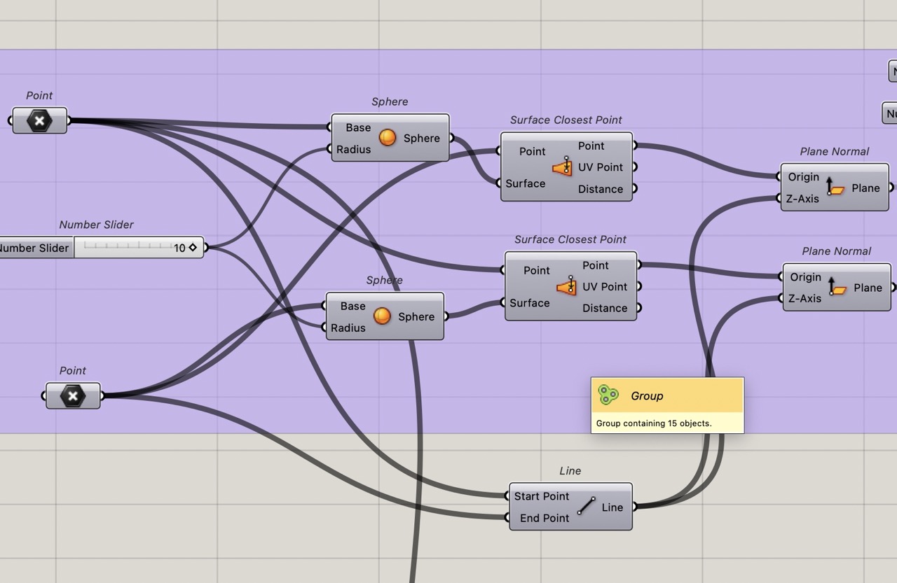
Add 2x surface closest point component to the canvas.
Connect the point to the point and the sphere to the surface.
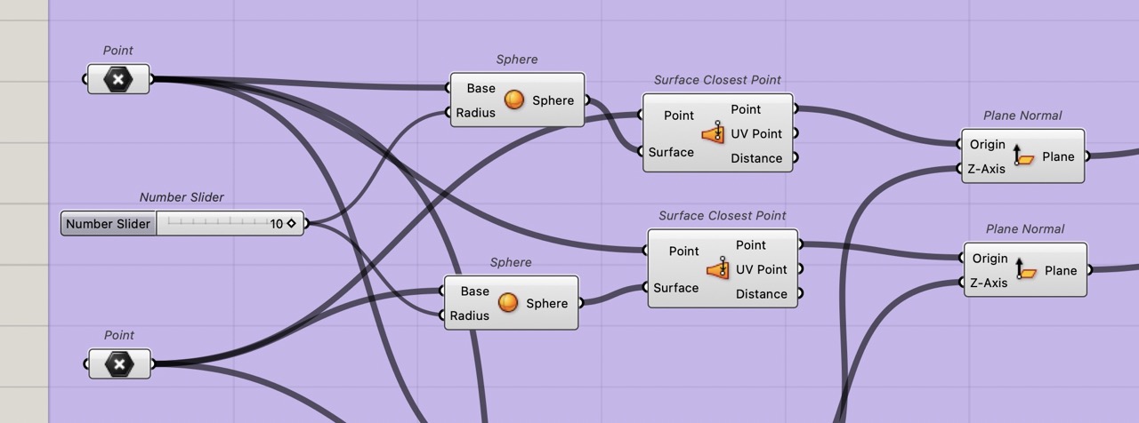
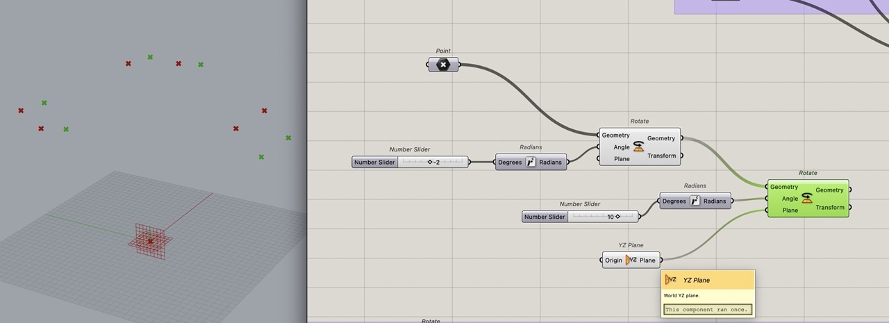
we can now add plane normal component
Connect the point from surface closest point output to the plane normal input.
We need a line for the normal so add line a2 point to the canvance
Connect the two original points to the line and connect this line to the z-axis of the plane
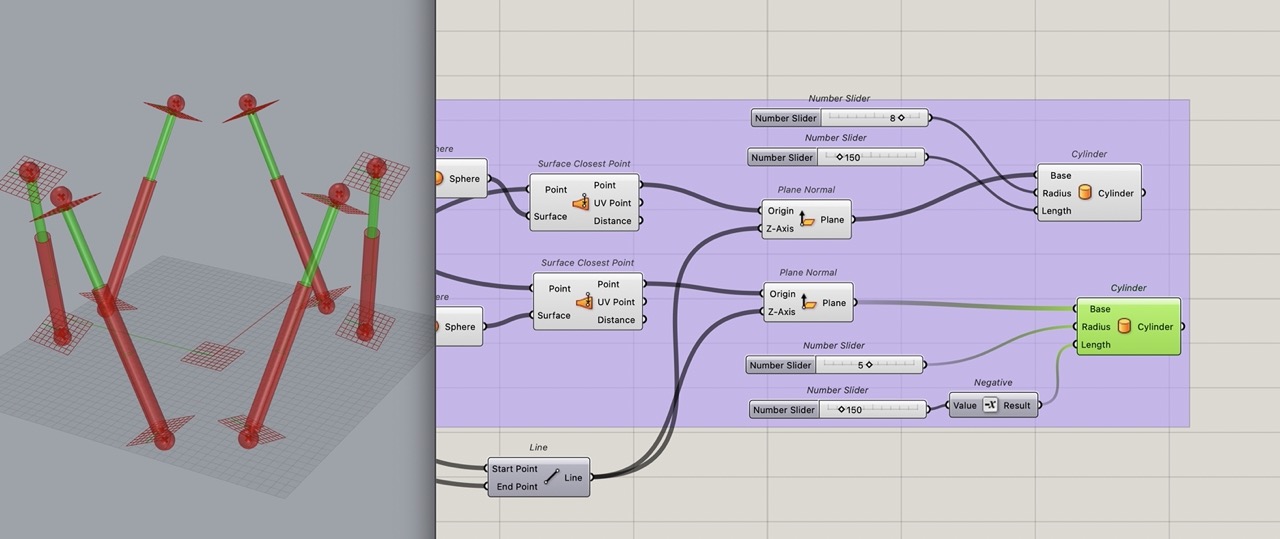
From this plane we can now model cylinders to represent linear actuators. These cylinders will have a fixed length but one will move inside the other. See screenshot below.
We now need to make the top plate adjustable.
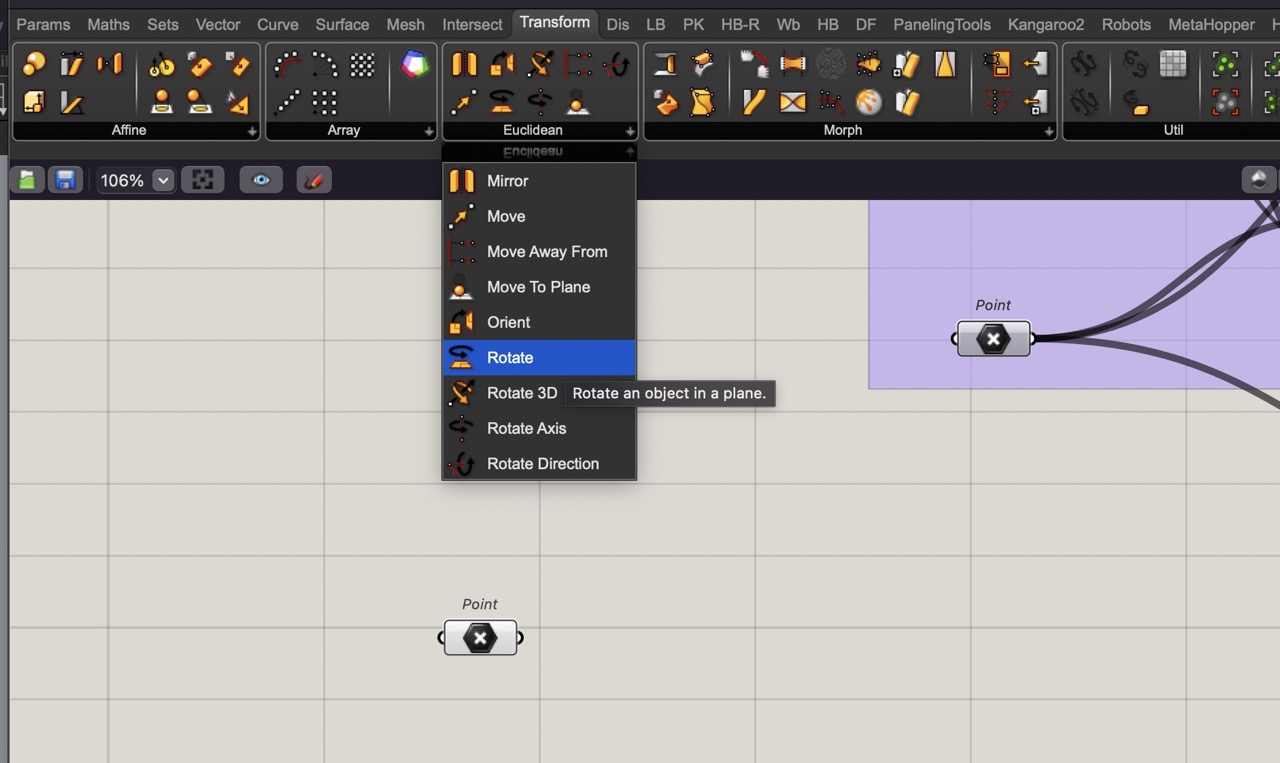
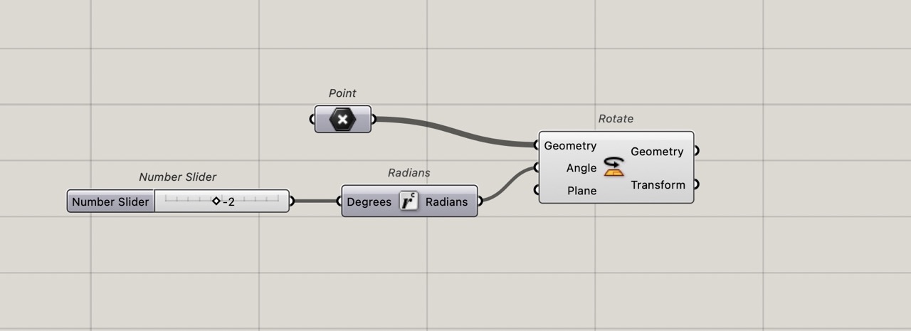
To do this we will use a series of move components, one for each transformation we want. Let's start with yaw. Add a rotate component to the canvas
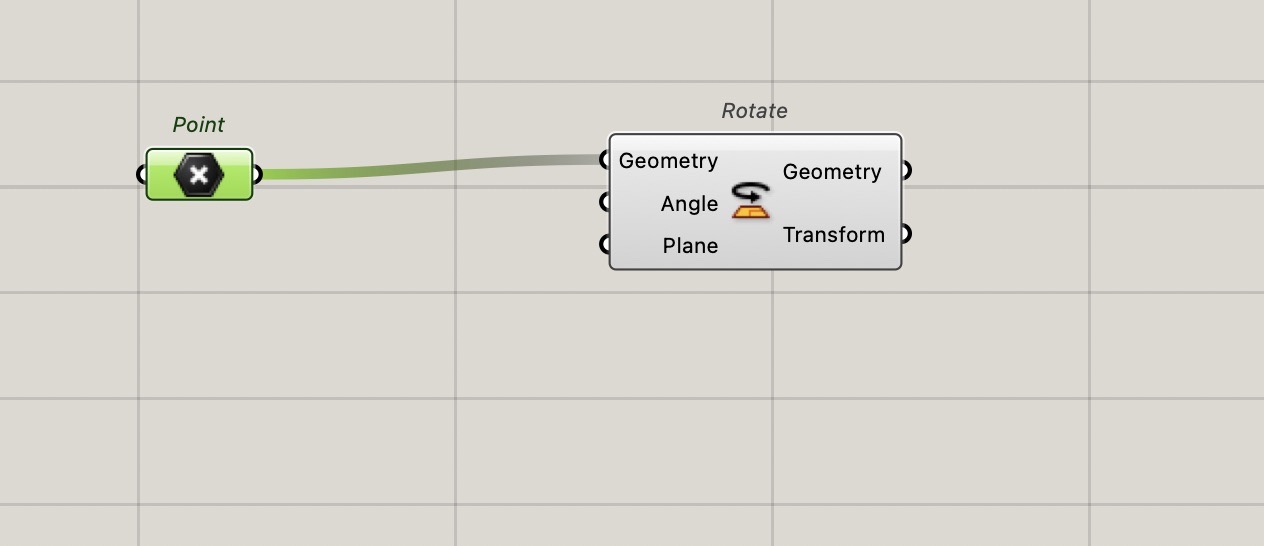
Connect the point command to the geometry
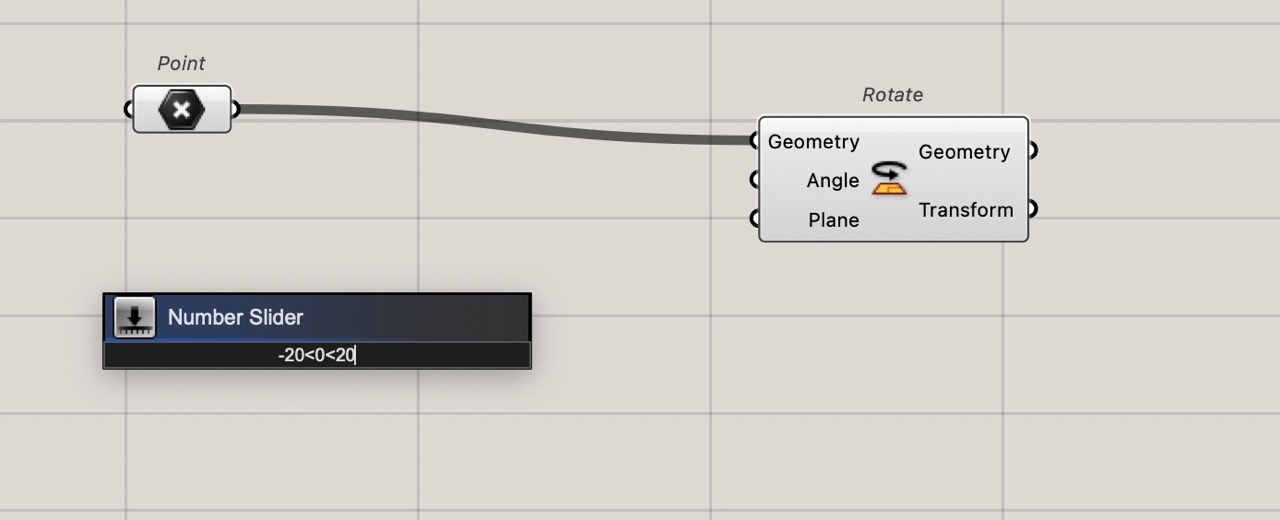
Add slider, double-click and set as image above - this will rotate from -20 deg to +20 deg and set at 0
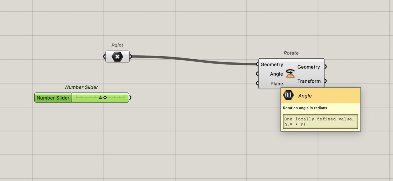
As Grasshopper defaults rotation angle to radians we need to convert the unit from degrees to radians - add this compinent
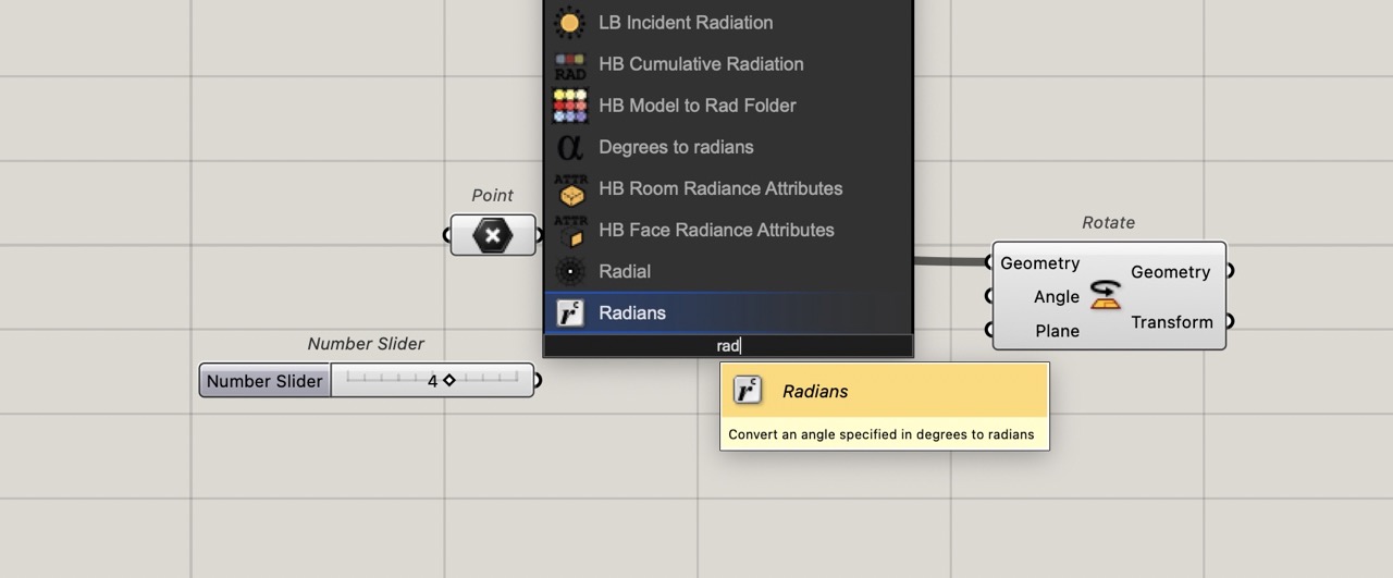
Connect to the rotate component - slide the slider and see the movement in the Rhino screen
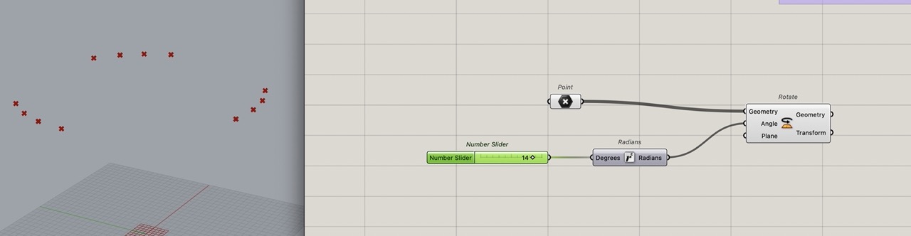
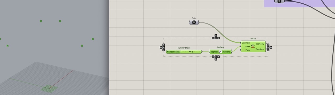
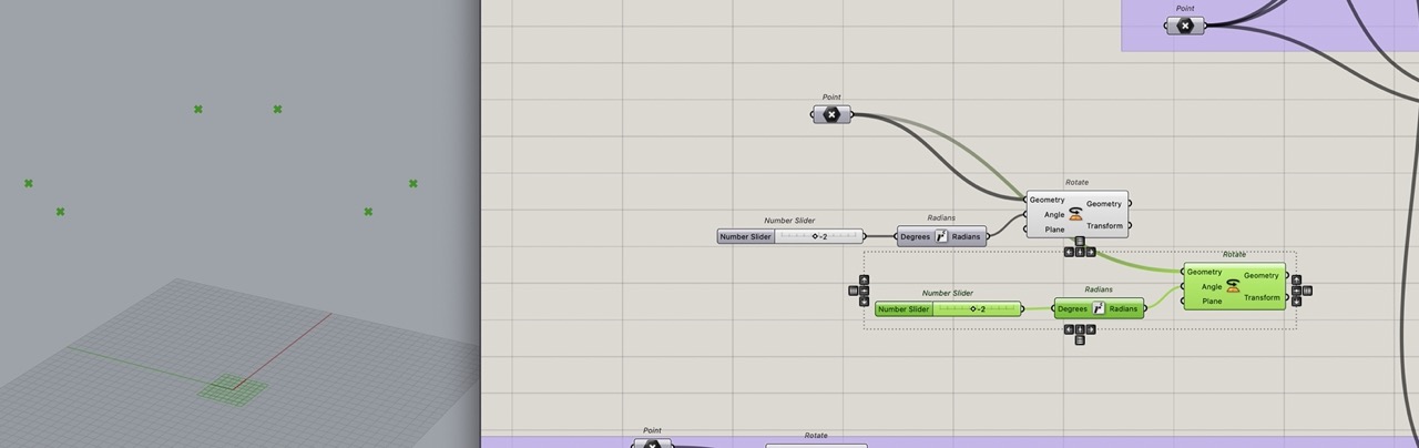
Select and copy the components, just add a YZ plane and it will give pitch. Copy again add XZ plane
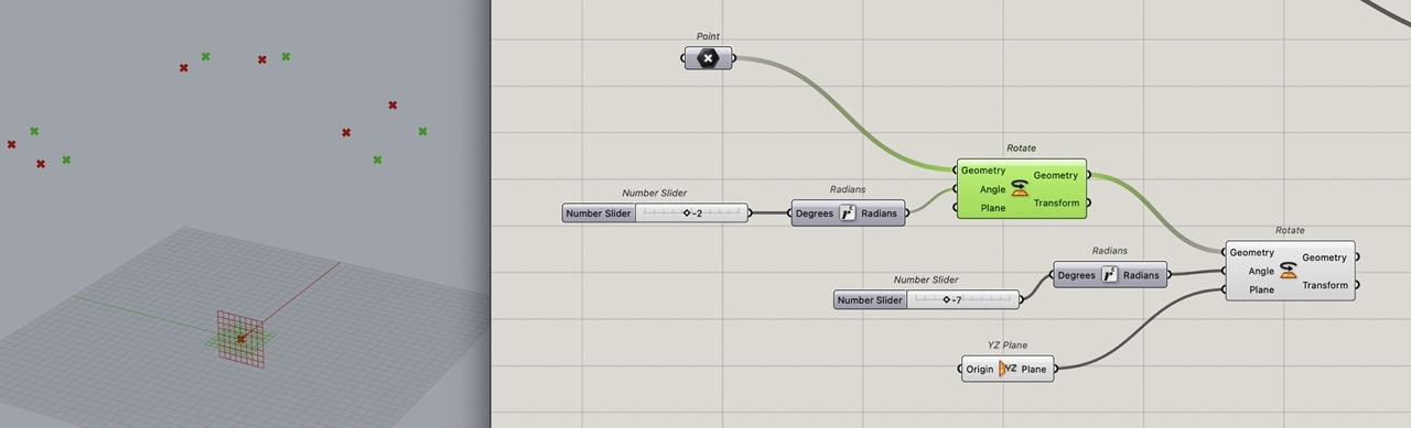
Do the same again but use move, see image below and rename the sliders accordingly
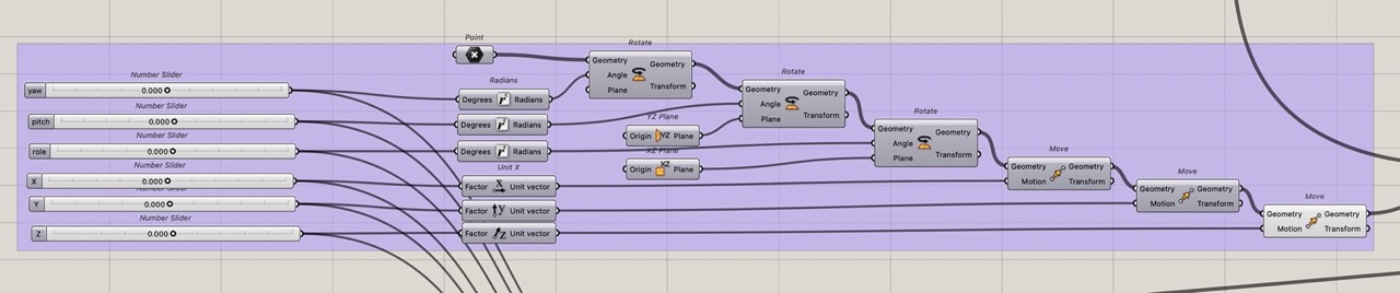
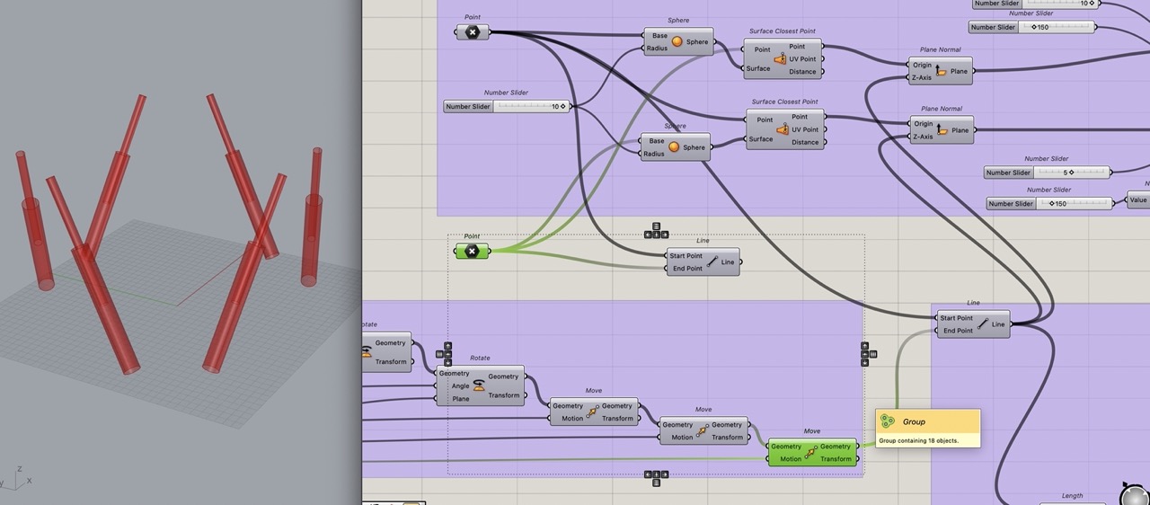
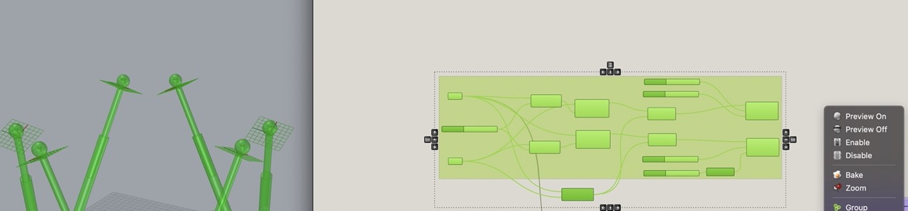
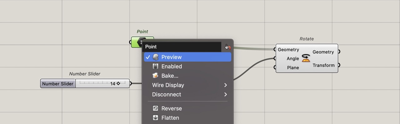
You can group and copy the block of components, change the point component to a geometry component and reference the top plate from Rhino - This will allow us to see the plate moving.
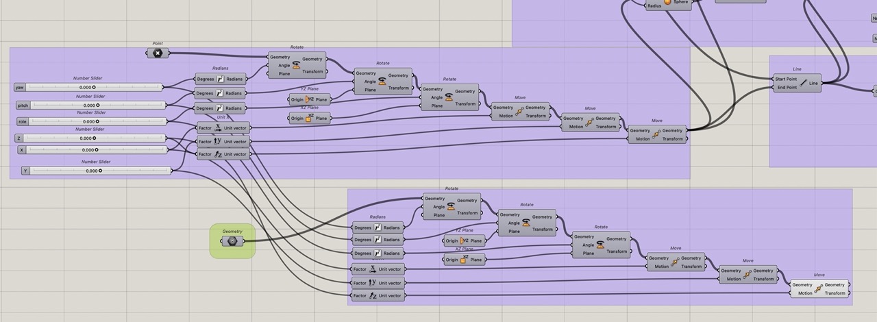
Hide preview for all components apart from the top plate (the last move component) and the cylinders. Move the sliders to see the top platform move.
2d Design
cursor AI used to help create the section below - I used the following prompt "I need to create a short, concise summary of bitmap and vector graphics under the section, 2D Design. I used Adobe Fresco to create the sample images pic_02_117 and pic_02_118. From a distance, they look the same; however, zoom in and they are different - can you explain why? You can also mention other packages like Adobe Illustrator and Adobe Photoshop."
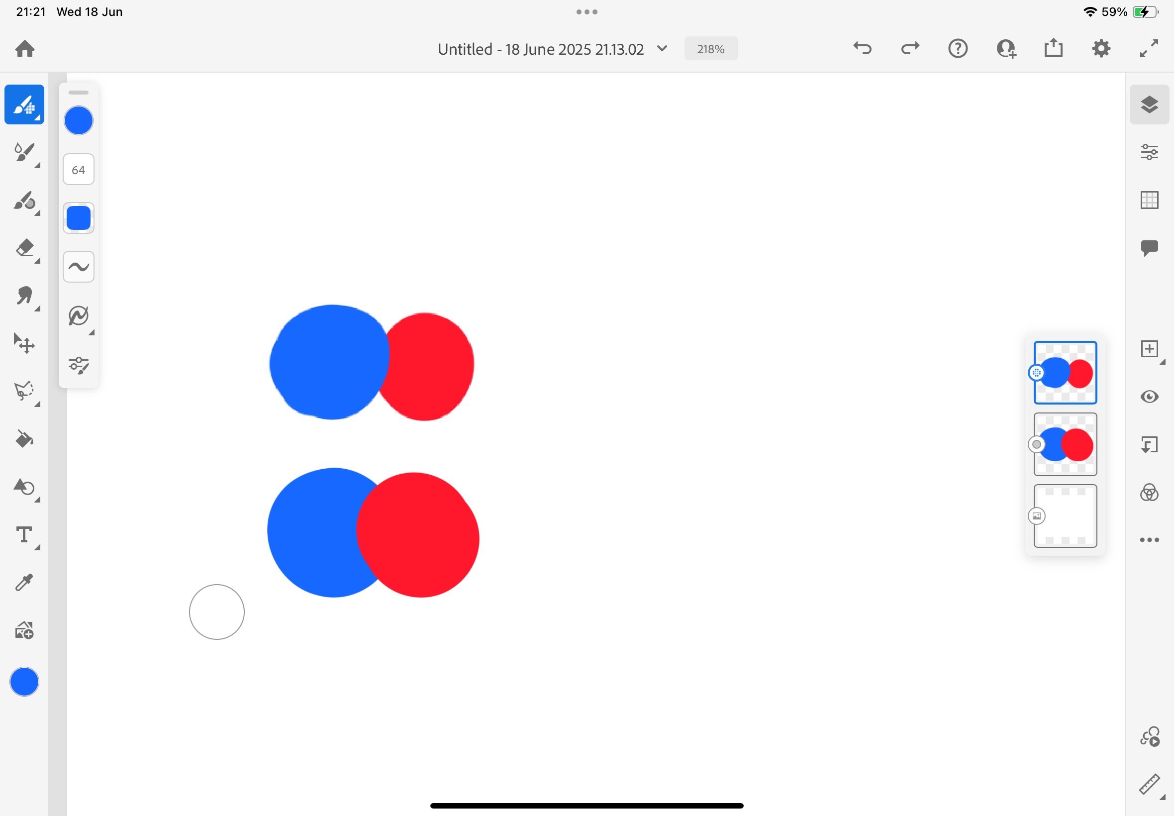
I used Adobe Fresco on the iPad to illustrate the fundamental differences between bitmap (raster) and vector graphics. Adobe Fresco can handle both vector and bitmap editing on separate layers, making it an excellent tool for demonstrating these concepts.
Bitmap vs Vector Graphics
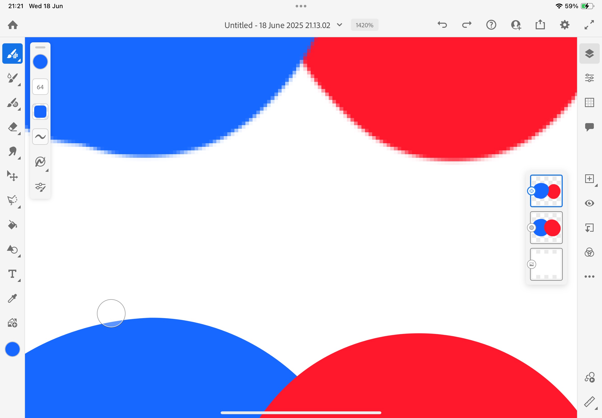
Bitmap (Raster) Graphics: These are composed of individual pixels arranged in a grid. Each pixel contains colour information, and the image quality is determined by the resolution (pixels per inch). When you zoom in on a bitmap image, you can see the individual pixels, which is why the image appears pixelated or blurry. Bitmap images are ideal for photographs and complex artwork with many colour variations.
Vector Graphics: These are created using mathematical formulas that define shapes, lines, and curves. Vector graphics are resolution-independent, meaning they can be scaled to any size without losing quality. When you zoom in on a vector image, the edges remain crisp and smooth because the mathematical formulas are recalculated for the new size.
The two Adobe Fresco images above demonstrate this difference. From a distance, they appear identical, but when zoomed in, the bitmap version (left) shows pixelation while the vector version (right) maintains crisp, smooth edges. This is why vector graphics are preferred for logos, icons, and illustrations that need to be scaled to different sizes.
Other 2D Design Software
Adobe Illustrator: The industry standard for vector graphics, Illustrator excels at creating scalable artwork, logos, and illustrations. It offers powerful tools for creating complex vector shapes, typography, and precise artwork.
Adobe Photoshop: Primarily a bitmap/raster editor, Photoshop is ideal for photo editing, digital painting, and complex image manipulation. While it can create vector shapes, it's not optimised for pure vector work like Illustrator.
Adobe Fresco: A newer addition to Adobe's suite, Fresco combines the best of both worlds with its ability to work with both vector and bitmap layers. It's particularly well-suited for digital painting and illustration work, especially on touch devices.
Image and Video Compression
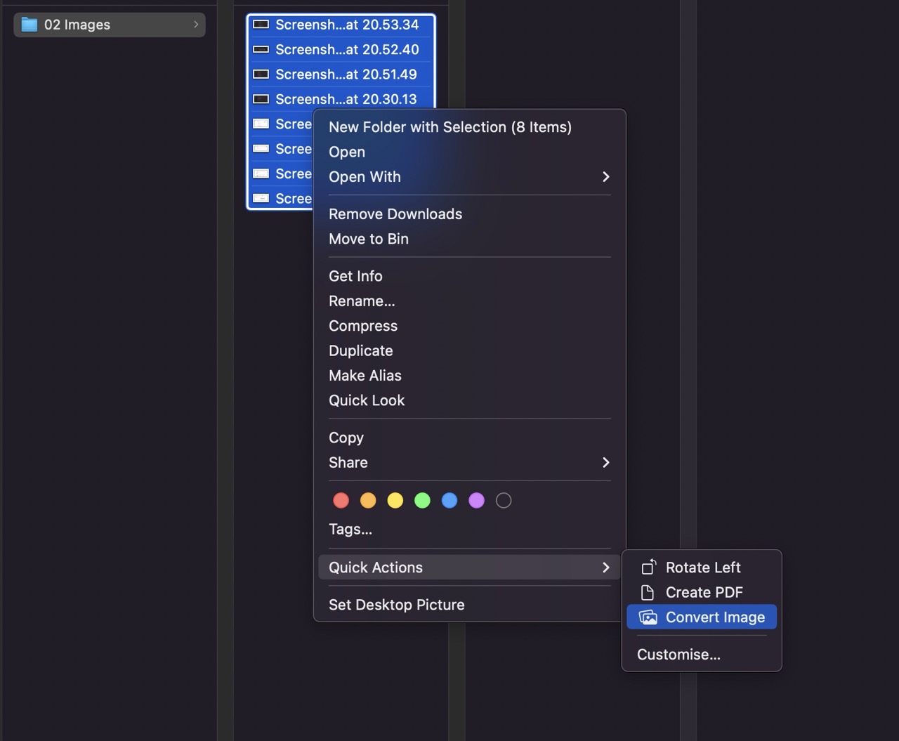
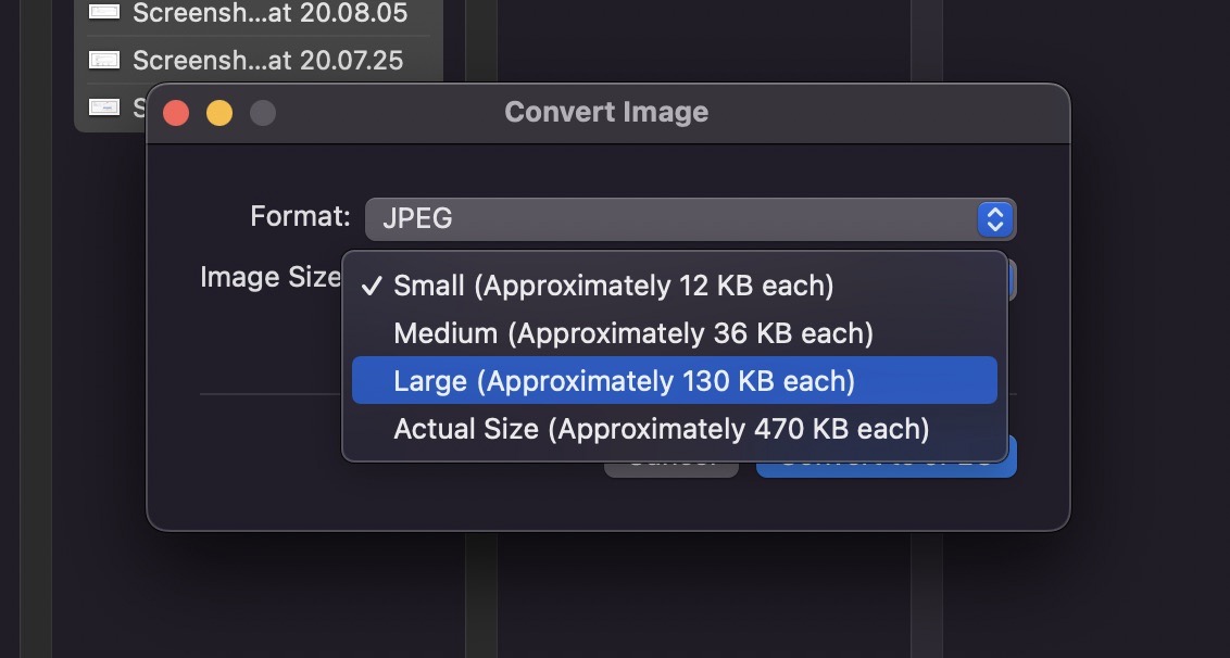
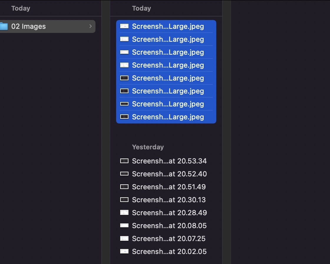
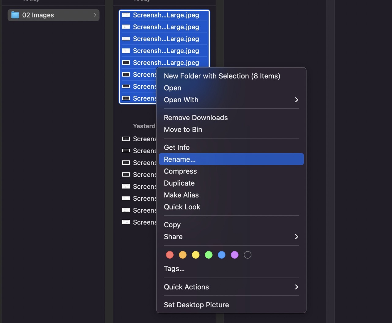
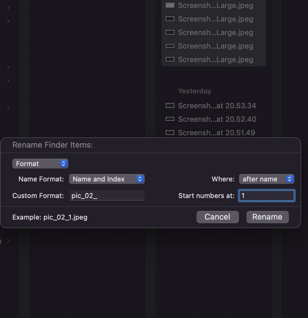
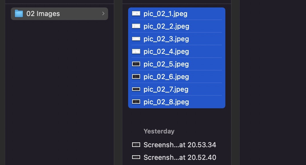
I use the built-in tools in Mac to compress images and screenshots.
The process is fairly straightforward. I organise the full-size images and screenshots in a folder. I then compress the images by selecting all the images - right-click and select quick actions. See screenshots below.
For video compression I'm using FFMPEG in the terminal on my Mac. Below is the command I use in terminal. The "-an" is used to remove the sound.

Learning Outcomes
Experienced using Fusion, Onshape and Rhino – of the three packages tested I prefer Fusion. Time didn't allow me to test other software; however, I would like to try more modelling in Blender – perhaps in the future.