Week 17. Applications and Implications, Project Development
What are we doing this week?

Assignment
Propose a final project masterpiece that integrates the range of units covered,
answering:
What will it do?
Who's done what beforehand?
What will you design?
What materials and components will be used?
Where will they come from?
How much will they cost?
What parts and systems will be made?
What processes will be used?
What questions need to be answered?
How will it be evaluated?
What tasks have been completed?
What tasks remain?
What has worked? What hasn't?
What questions need to be resolved?
What will happen when?
What have you learned?
Your project should incorporate 2D and 3D design,
additive and subtractive fabrication processes,
electronics design and production,
embedded microcontroller interfacing and programming,
system integration and packaging.
Where possible, you should make rather than buy
the parts of your project.
Projects can be separate or joint, but need to show individual
mastery of the skills, and be independently operable.
Final Project Proposal
What will it do?
The Steady Platform is intended to hold a printer steady while printing on the move. Below is a video of the journey to the Fab Lab - on which I would like the platform to be able to remain steady.
Who's done what beforehand?
I have seen a few projects that have used a similar concept of building Stewart platforms, but not necessarily using it for the purpose I intend to use it for.
I found some links to existing hexapod designs:
NicHub Stewart-Platform-Esp32 GitHub
Video and GitHub link for motion tracking hexapod code in Python:
Yeok-c Stewart_Py YouTube
Yeok-c Stewart_Py GitHub
Yeok-c is the one I used the most as he had great documentation on the inverse kinematics and the programming.
What will you design?
I will be designing a Stewart platform or hexapod to hold a printer steady in the back of a mobile Fab Lab driving on the road. A platform that will cancel out the bumps and motion experienced when driving on the road.
What materials and components will be used?
I will be using a range of materials from the Creative Spark Fab Lab - 3D printed components where possible, utilising FDM (PLA and PETG) and SLS (Nylon 12) printing processes.
XIAO RP2040 - microcontroller
6x Servo Motors SunFounder TD-8120MG Digital Servo - rated to 20kg each
Servo Driver PCA9685 - 16 channel
Adafruit BNO085 9DOF accelerometer and gyroscope
Mean Well RSP-150-7.5v 150watt power supply
Carbon fibre rods
Epoxy
Where will they come from?
Digi-Key for most of the electronic components,
Amazon for the carbon fibre tubes.
Prusament PETG for the FDM printed parts,
Form Labs Nylon 12 for the SLS printed parts.
Plywood for the base plate - Sourced from the Fab Lab
Amazon for the Universal Joints on the top plate.
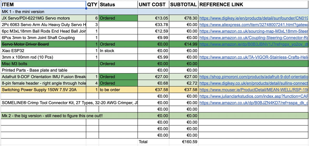
How much will they cost?
Full costing is listed in the Bill of Materials - total cost to date is £163.62 (not including items sourced from the Fab Lab, print filament, powder and electronic components).
What parts and systems will be made?
As much as possible - I have designed most of the components in Autodesk Fusion and printed the main body, platform top and the ball joints for the servo arms. The main PCB that holds the microcontroller, LEDs, buttons and connector terminals for the breakout boards. I would like to incorporate a 3.3V voltage converter; however, for the time being, I will run the RP2040 from the USB-C cable connected to laptop.
What processes will be used?
3D Printing both FDM and SLS
PCB board Milling - and production using the Roland SDM 20 - PCB milling machine
Laser cutting to produce the Base to hold the Stewart platform and the power supply
Soldering to produce the PCB board
Arduino IDE for programming the microcontroller
Cursor AI for coding the inverse kinematics and the PID loop
What questions need to be answered?
How will the platform be able to hold the printer steady while driving on the road? - this is the main question that needs to be answered - I will be using the PID loop to keep the platform steady - I will be using the accelerometer and gyroscope to sense the movement of the platform and the printer - and the servo motors to move the platform to keep it steady.
How will it be evaluated?
- Will it be able to hold the printer steady while driving on the road?- Will it be able to print while driving on the road?
- Will it hold something steady - I'll practice with a small version - time constraints prevent me creating the full-size model that would be capable of holding a full-size printer
What tasks have been completed?
Final Project CAD has been completed
3D Printed Parts have been produced
The main body of the Stewart platform has been assembled and the servos calibrated
Inverse kinematics has been completed and set using the CAD model for measurements
Manual control code has been created and tested - the platform moves up and down its full extent - but it is not yet able to hold the top plate steady.
See video below - if all comes to all this project might just become a teddy lift lol.
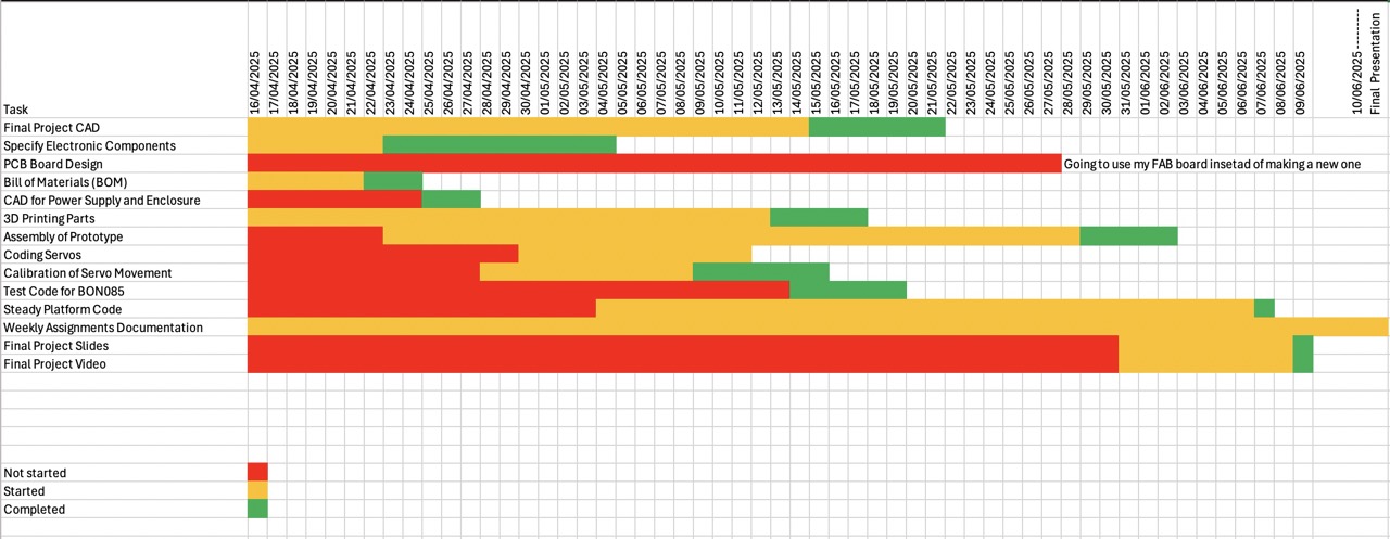
Below is the Gant chart and progress to date.
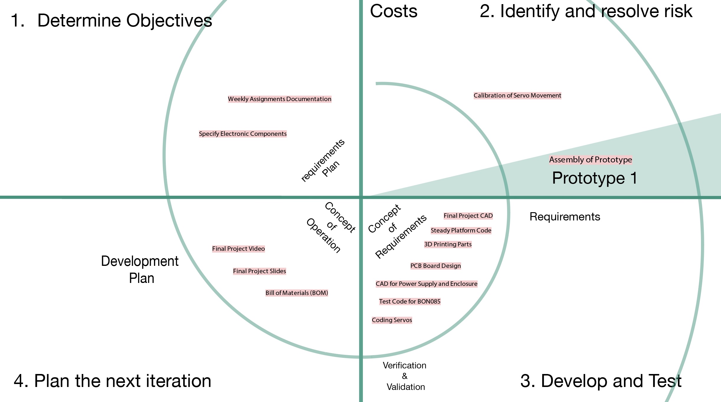
A zoomed in image of the spiral development with my specific tasks added to it for this project.
What tasks remain?
In terms of the final project as of now I still need to complete my final code to be able to self-level - I will be leveraging Cursor AI to help with this.
I need to complete final presentation video and slide - the above was the placeholder link - it is now likely the final presentation and slide if viewing this after the 13th June 2025.
I need to laser cut the base to hold the Stewart platform and the power supply
3D print the electronics power supply cover
I need to make a bigger platform - this one is very much spiral 1 - I would like to upscale it to be able to hold a full-size 3D printer. However, this will not happen during Fab Academy 2025 - perhaps later.
A better cable to connect the PCB board to the BNO085 and the servo driver.
What has worked? What hasn't?
The system seems to work - it has less movement than I would like - this is likely down to the ball joint design at the servo arm - I will make the ball joint bigger to increase the range of motion.
Additionally, I had a 0.075mm tolerance in the ball joints - this was too much as the joints are loose and wobble a little - when redesigning these I will model face to face or possibly an interference fit approximately +0.05mm or +0.075mm to have a tighter fit.
The cable connecting the PCB board to both the BNO085 and the servo driver had connectors that are too loose - I will need to make a new cable and find better connectors - the board itself can cause the connectors to come loose when it moves in a particular way.
What will happen when?
This is stage one for the steady platform development - there are some things that need to be addressed in the short term: 1. The cable connectors - 2. The ball joints on the servo arms - this will require a redesign and reprint of the parts. 3. The cable itself - I need to either make a better one or redesign a bespoke board for the Stewart platform - I hope to do this in the coming months so that I have a more robust system to use for future projects and applications.
I do like the idea of using the Stewart platform as a multi-axis platform.
What have you learned?
Technical Skills:
- Inverse Kinematics: Successfully implemented mathematical calculations for Stewart platform control
- PID Control Systems: Developed feedback loops to maintain platform stability
- Embedded Programming: Integrated multiple components (accelerometer, servos, microcontroller)
- 3D Design & Printing: Designed and fabricated custom components with specific tolerances
- PCB Design: Created functional circuit boards for system integration
Engineering Insights:
- Tolerance Design: Learned that 0.075mm tolerance was too loose for ball joints, requiring tighter fits
- System Integration: Successfully connected multiple electronic components (BNO085 sensor, PCA9685 driver, RP2040 microcontroller)
- Motion Control: Developed a working self-levelling platform that responds to movement
Project Management:
- Iterative Development: Recognised the value of spiral development (this being "spiral 1")
- Time Management: Experienced the challenge of completing complex projects within time constraints
- Problem Solving: Identified and documented specific technical issues for future improvement
Technical Challenges Overcome:
- Connector reliability issues
- Ball joint design optimisation
- Cable management for moving systems
- Integration of multiple sensor and actuator systems
Issues I've encountered
AGHHHHH!
What went wrong... I'm not going to get the full-size steady table built... I've run out of time!

What went wrong.
