Week 13. Molding and Casting
This week we are learning about molding and casting.
Group assignment: (link here)
Review the safety data sheets for each of your moulding and casting materials,
then make and compare test casts with each of them.
Compare mould making processes.
Individual assignment:
Design a mould around the process you'll be using,produce it with a smooth surface finish that
does not show the production process toolpath,
and use it to cast parts.
Extra credit: use more than two mould parts.
Moulding and Casting
This week I decided to use the rotocasting machine we built during machine building week.
My intention was to mould some small chocolate bunny figurines using the rotocasting process.
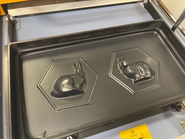
My initial plan was to 3D print a mould and vacuum form the mould to rotationally cast the parts.
However, I did not have any food-safe materials for vacuum forming – which I only realised after already printing the moulds.
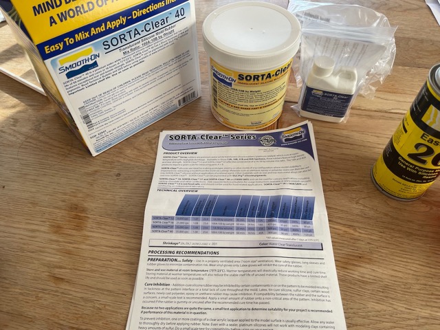
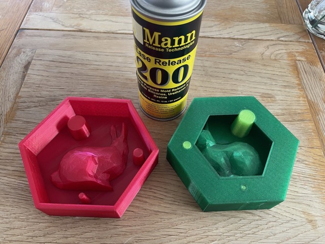
So I decided to then 3D print a tool in PETG and cast a mould using Smooth-On Sorta-Clear 40, a food-safe silicone.
Below is the data sheet showing the pot life and various health and safety information.
 Below is the process I followed.
Vacuum Forming
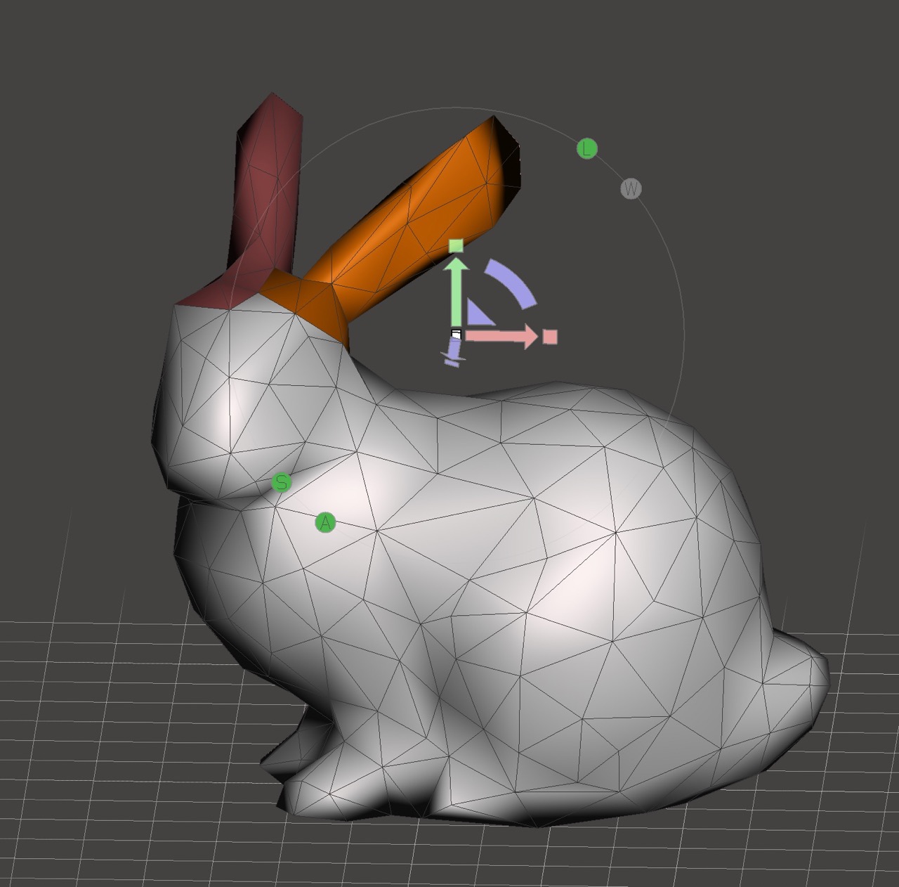
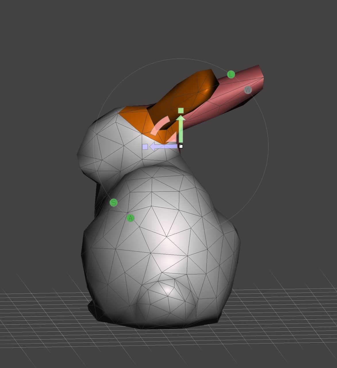
3D modelling – for this I am using the sample bunny file from Meshmixer – the part is then adjusted in Meshmixer to change the ears to a more suitable position and shape for moulding.
Making a low-poly version of the model by decimating the mesh in Meshmixer.
I then exported the model from Meshmixer and imported it into Autodesk Fusion.
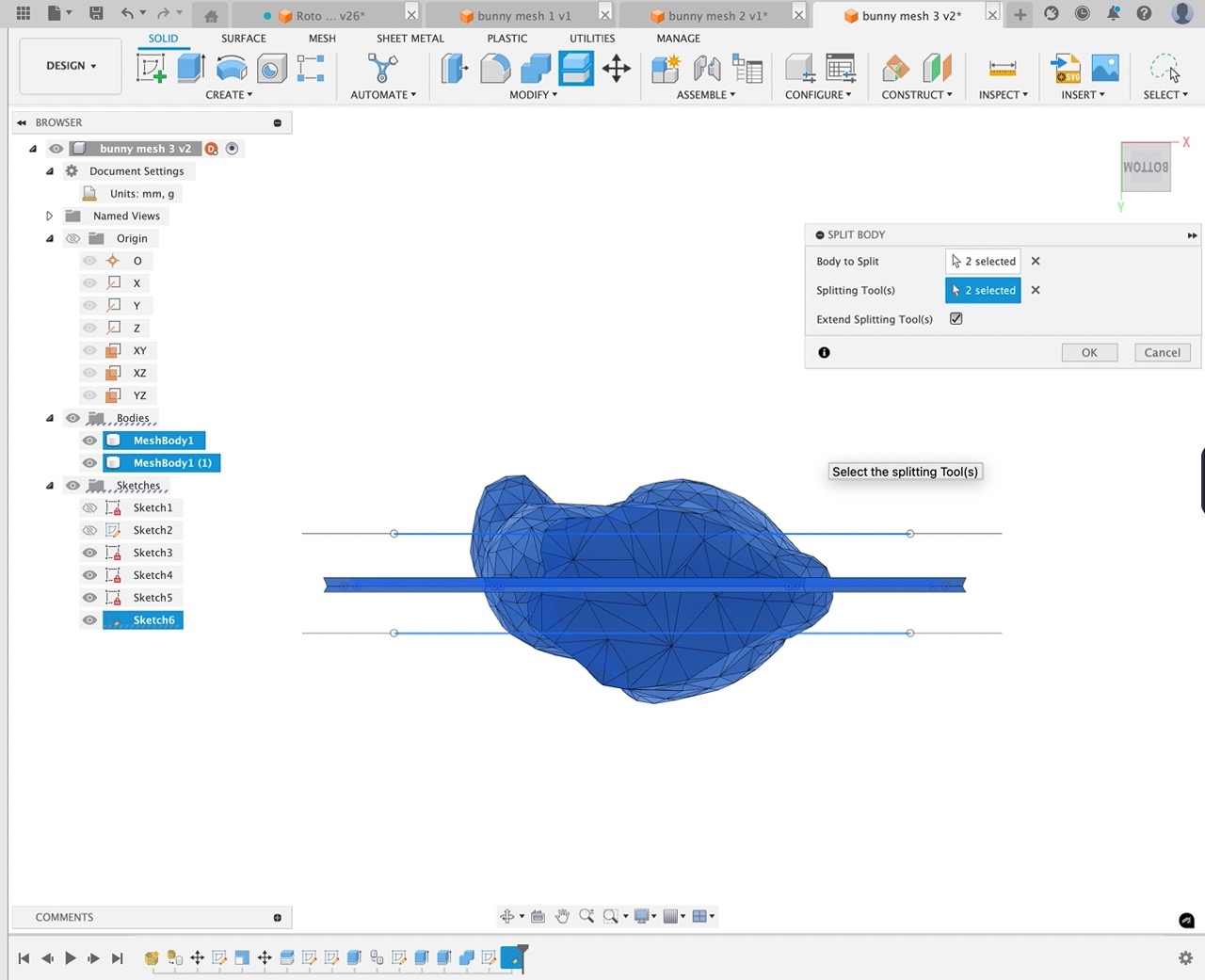
I then split the part in Autodesk Fusion and added a base for vacuum casting with a registration band around the edge.
I added some planes to split the bunny in half and then also the top portions of each half. This was to add different infill parameters in the slicing software, which we will see later.
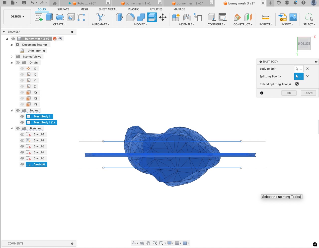
Here I am using the sketch geometry to split the bodies.
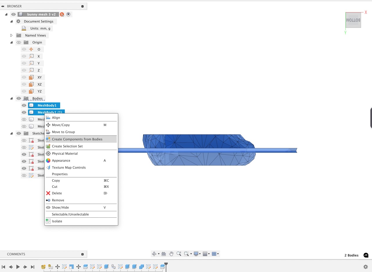
I then create components from bodies. I select the two lower body parts from each half to do this. When completed, I then move the corresponding top into the appropriate component.
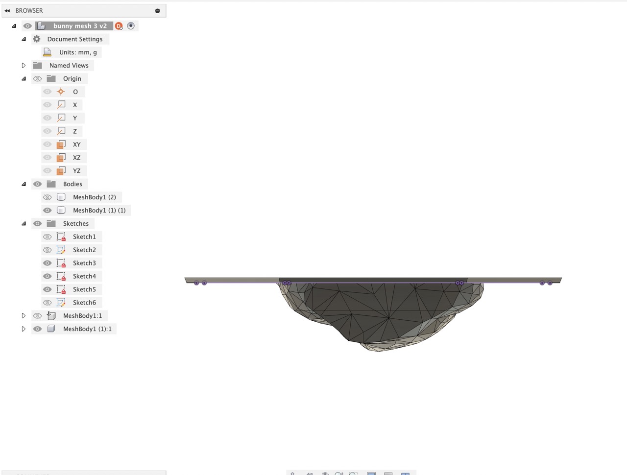
The file is saved in Fusion and to send to 3D print we can right-click on the component in the browser and save as mesh.
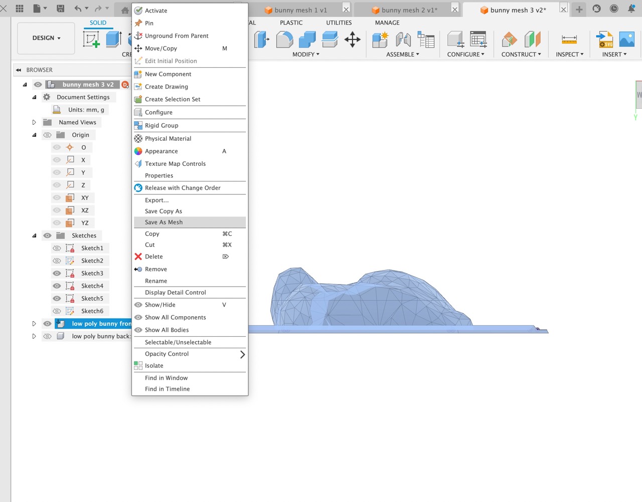
We can then select to send to print utility - in my case, I chose Prusa Slicer.
As we would be vacuum forming, I decided to use 0 walls, 0 top layers and 0 bottom layers.
I split the top part off the model to make the infill more dense - 70% gyroid infill.
The lower part was 50% gyroid infill.
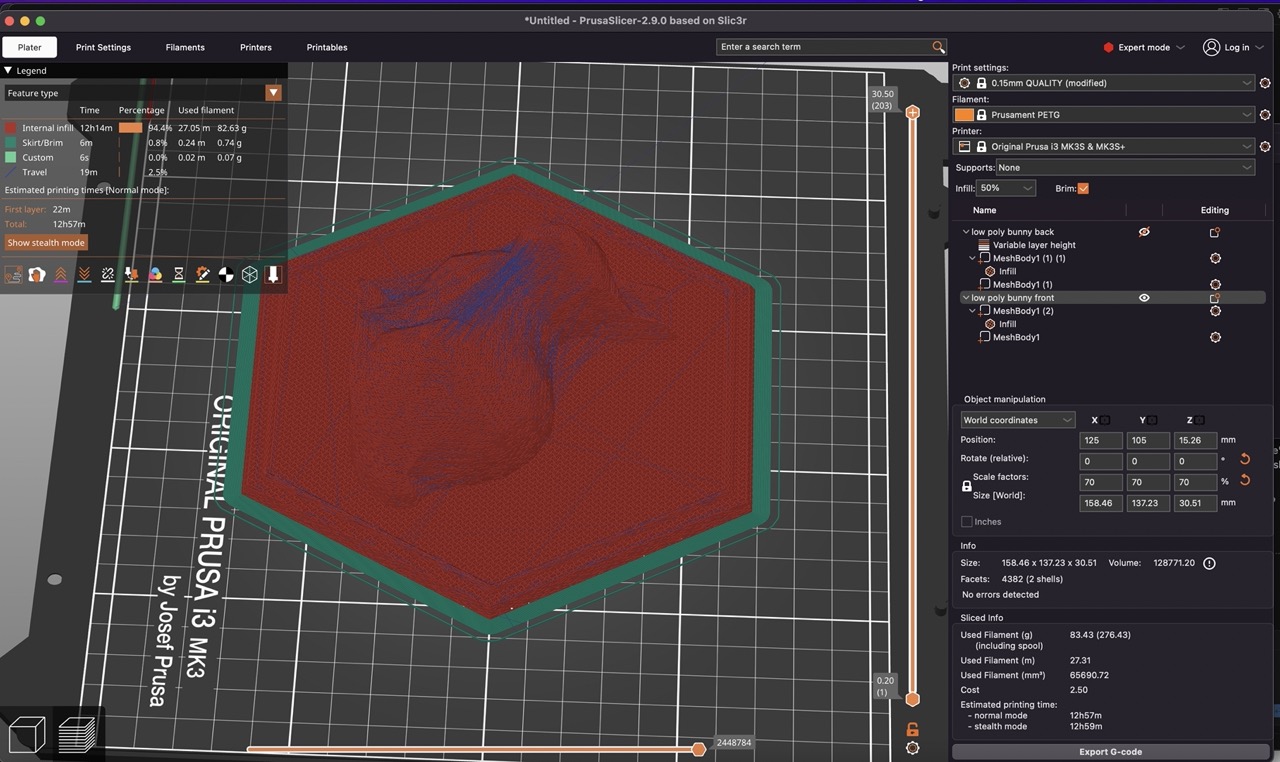
This would allow the vacuum forming to pull the plastic to the surface of the mould.
I exported the sliced file from Prusa Slicer to an SD card to be printed on the Prusa MK3S+ printer.
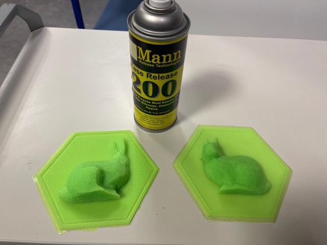
Three to four coats of Mould Release 200 were applied to the printed parts, allowing a few minutes drying time between coats.
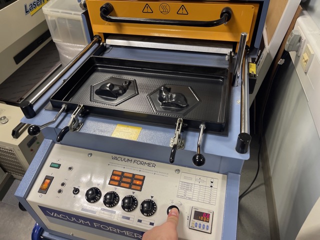
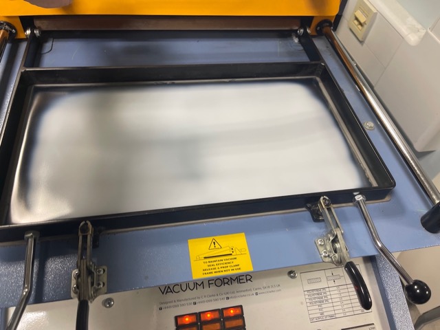
The mould was then placed in the Vacuum Forming machine and dropped the platform.
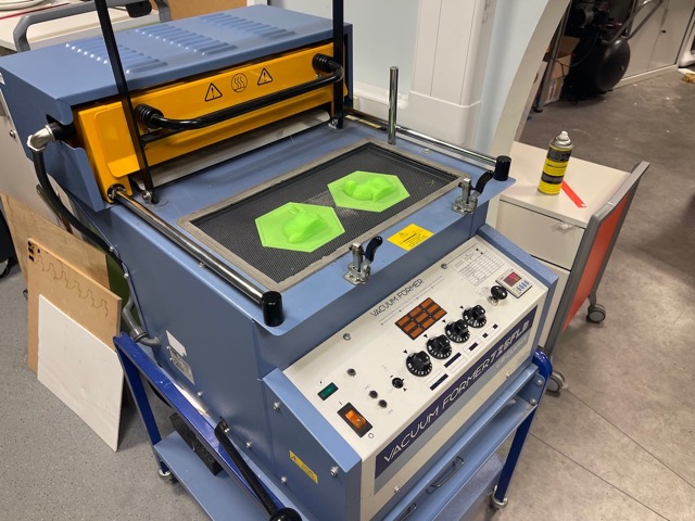
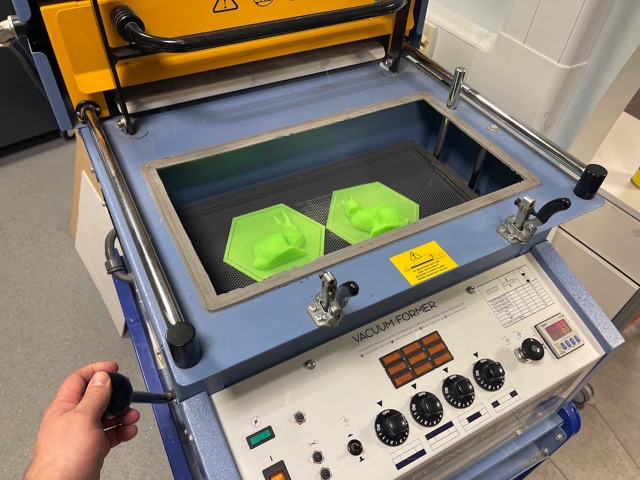
Material added and clamped in place.
Timer was set and the heater was turned on and brought over the material to be heated.
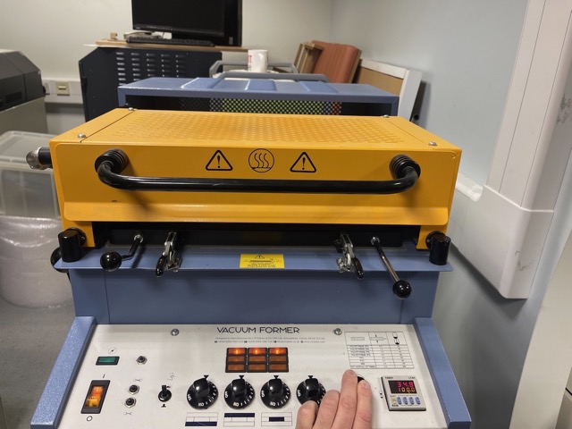
During heating, air can be pumped into the former to prevent the plastic sagging if needed.
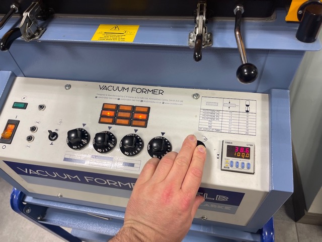
A close eye needs to be kept on the material to prevent burning and overheating.
When material is ready, the heater can be pushed back and the mould can be raised with the handle to the left.
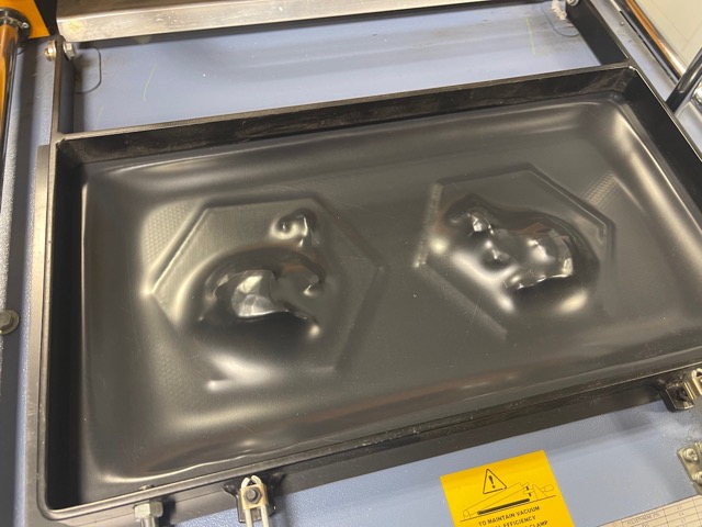
Vacuum can be applied which will pull the plastic to the surface of the mould.
This can be held for a few moments to allow for the plastic to cool.
We can then reverse the vacuum to push the plastic off the mould.
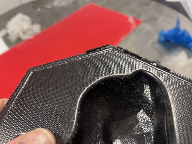
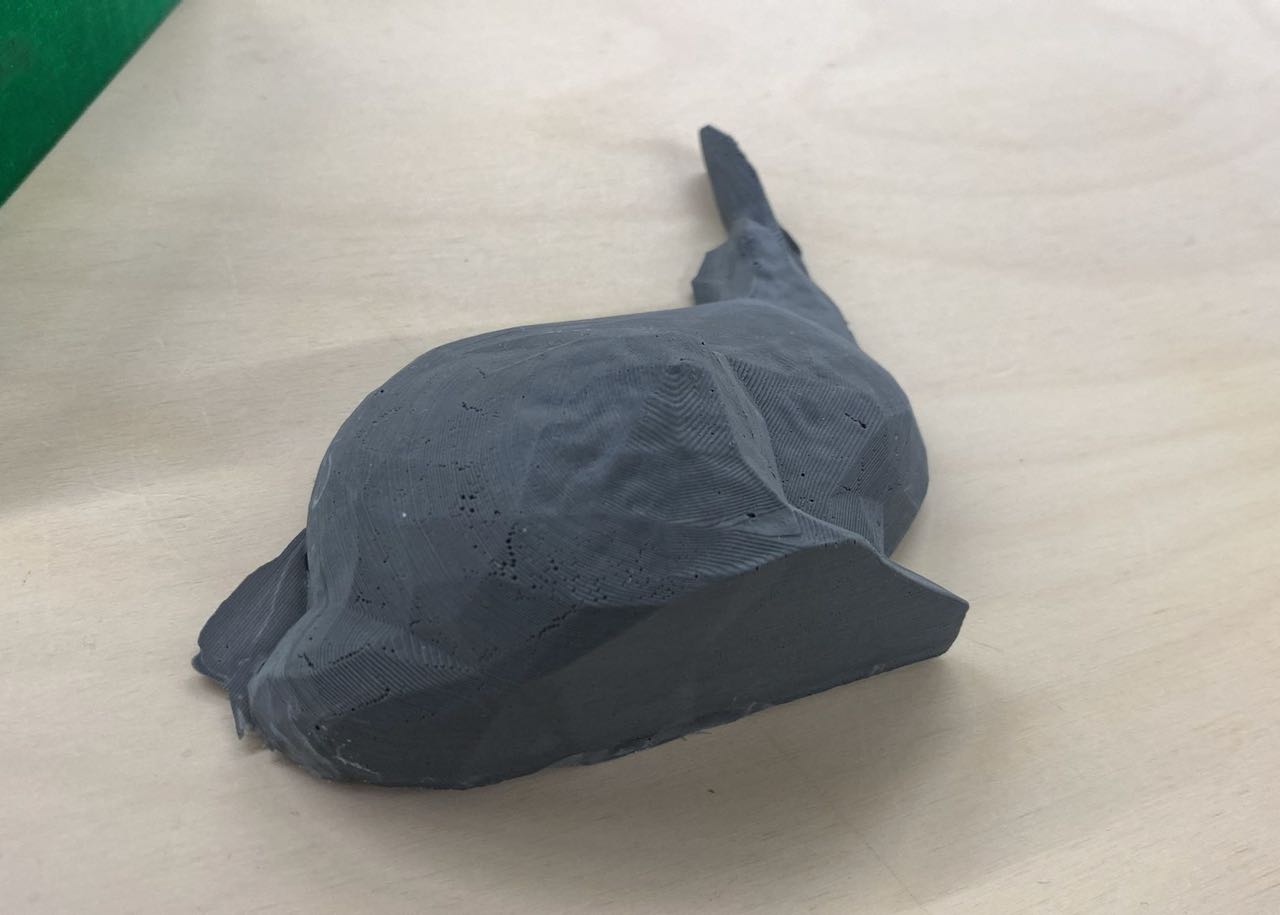
The moulds can be taken out and the protective film can be removed.
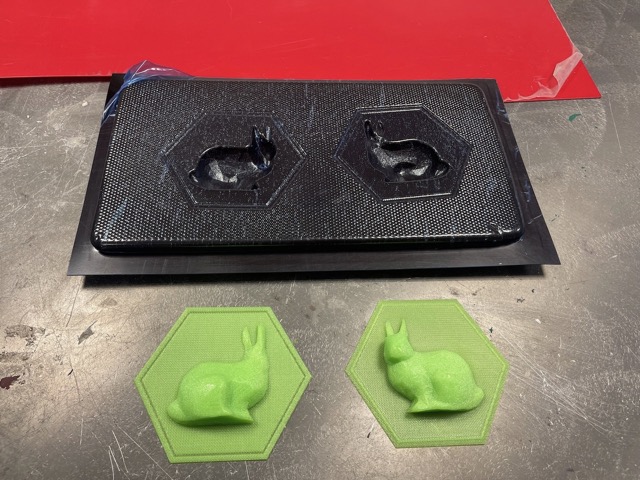
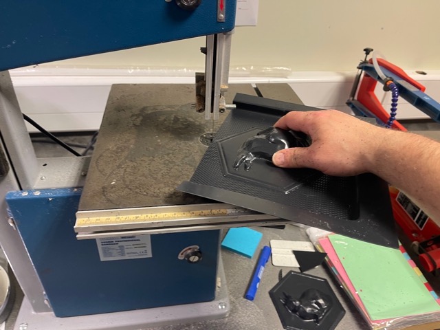
And excess material trimmed with a bandsaw - (wear ear protection, it gets loud).
Silicone Casting
Making the mould
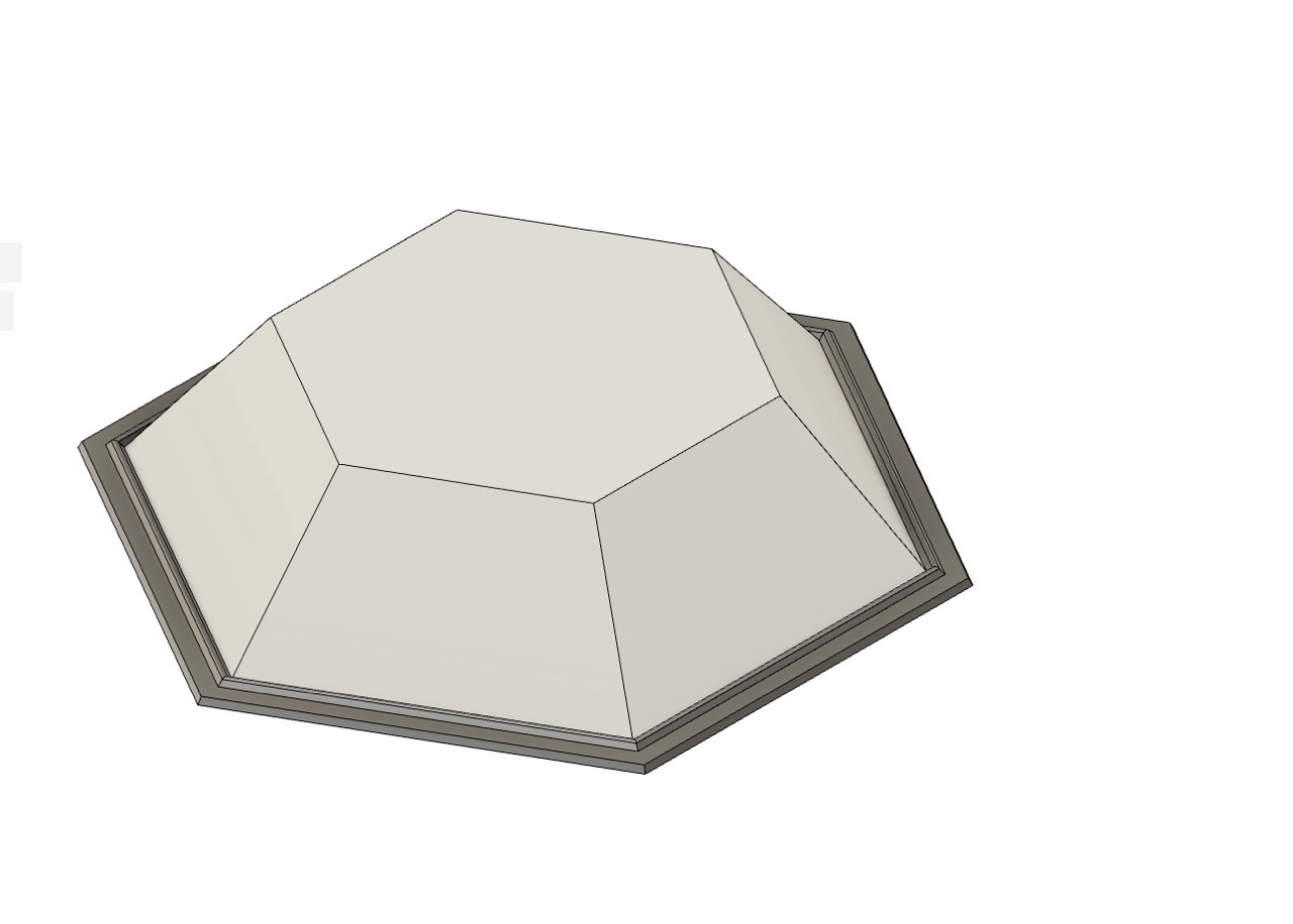
I began by modifying the CAD to produce a mould to pour the silicone into.
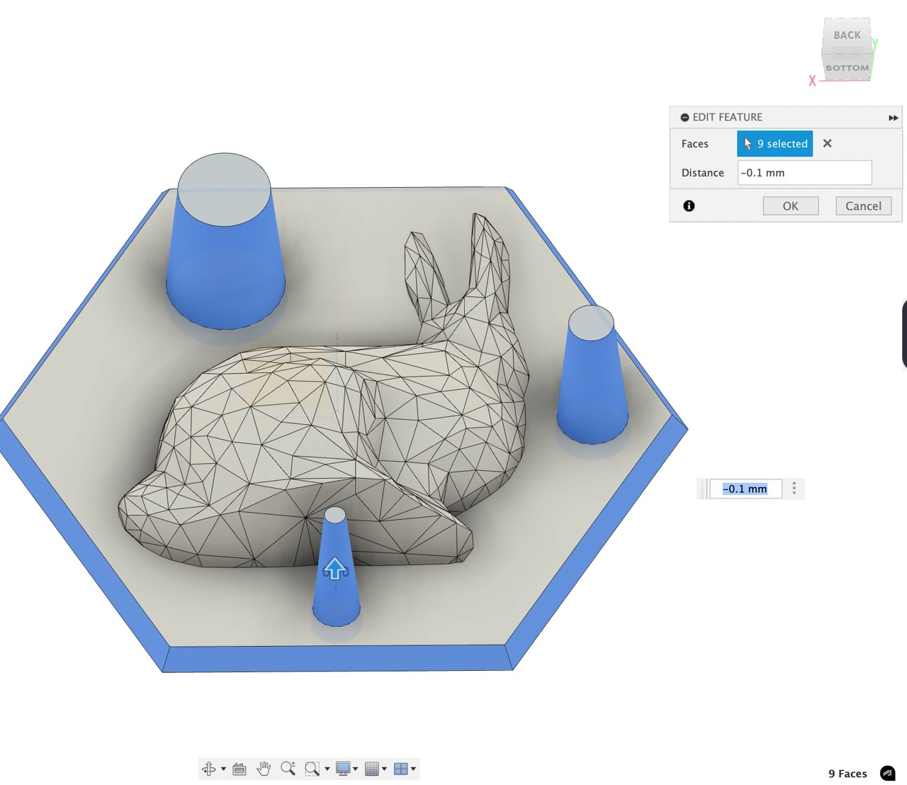
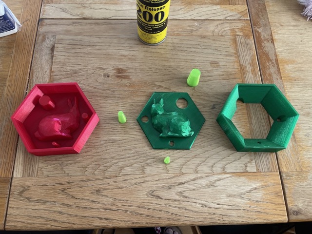
After the poor attempt at registration with the vacuum forming, I decided to make some better registration locators.
These could be printed and added to the two parts of the mould to allow better registration.
I again printed using PETG - after printing the first part of the mould, I realised that it would be quite large.
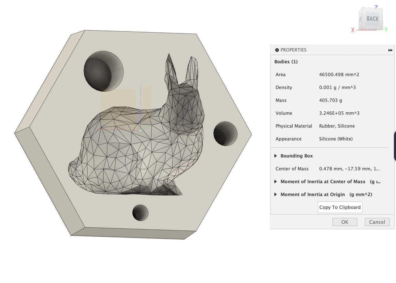
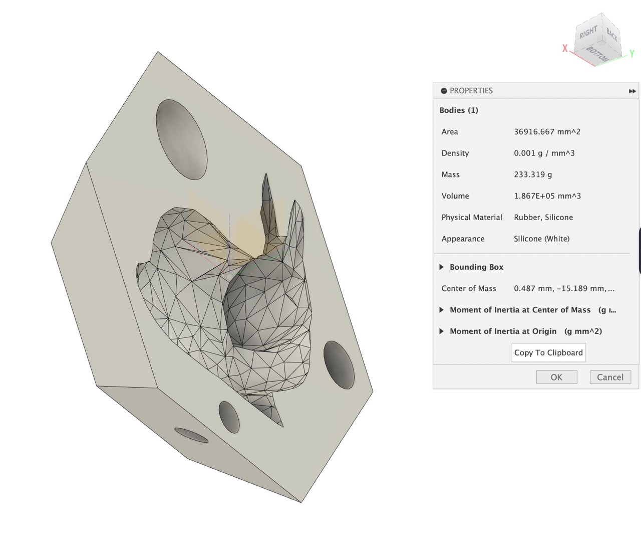
I checked the mass of the silicone mould in the Autodesk Fusion model; each half was approximately 405g.
As we only had 900g of Sorta Clear 40, I decided to look at removing some weight from the mould.
I also wanted to improve the mould to ease removal of the parts - to do this I added a large amount of draft to the walls of the mould.
After doing this I was able to almost remove the mould mass by half; it was now calculating at 233g each.
I also added a 0.1mm of tolerance to the touching faces of the locator pins and the mould and mould walls. (Ultimately this was not needed as silicone leaked out around this).
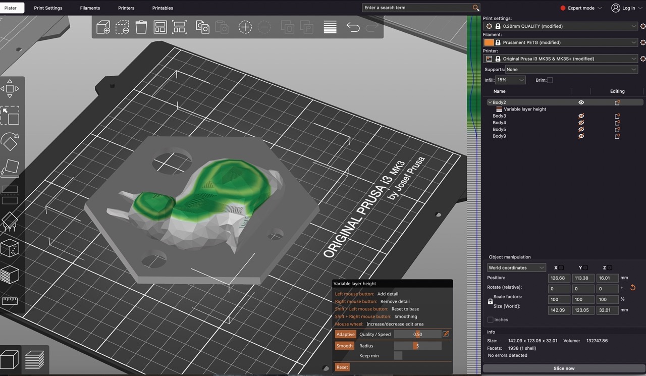
I exported to Prusa Slicer, increased the walls to x3 and added a little to the top and bottom layers. I also used variable layer height in Prusa Slicer to minimise layer lines.
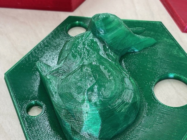
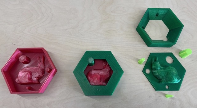
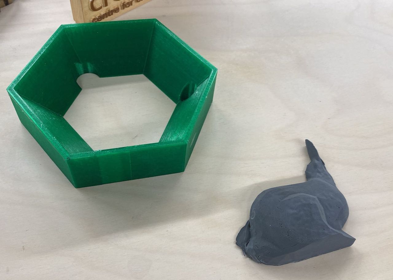
The images below show the printed moulds to make the silicone tool. The one on the left was V1 and the one on the right is V2 which uses less silicone and the mould can be disassembled for easy removal of the silicone tool.
And increased the infill to 25% (this probably could have been a bit more).
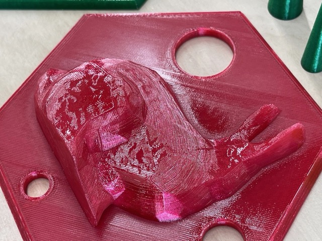
When printed, to remove the layer lines I used heat in the form of a soldering torch.
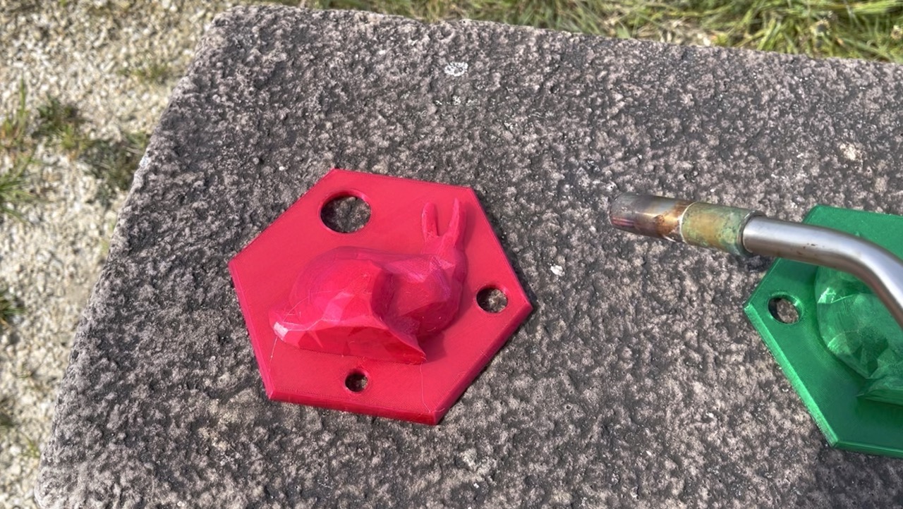
This was a delicate process of blasting heat at the layers and hoping the whole thing wouldn't go up in flames or completely melt.
I would not recommend this if parts were dimension critical. Note I did this outside on a suitable surface.
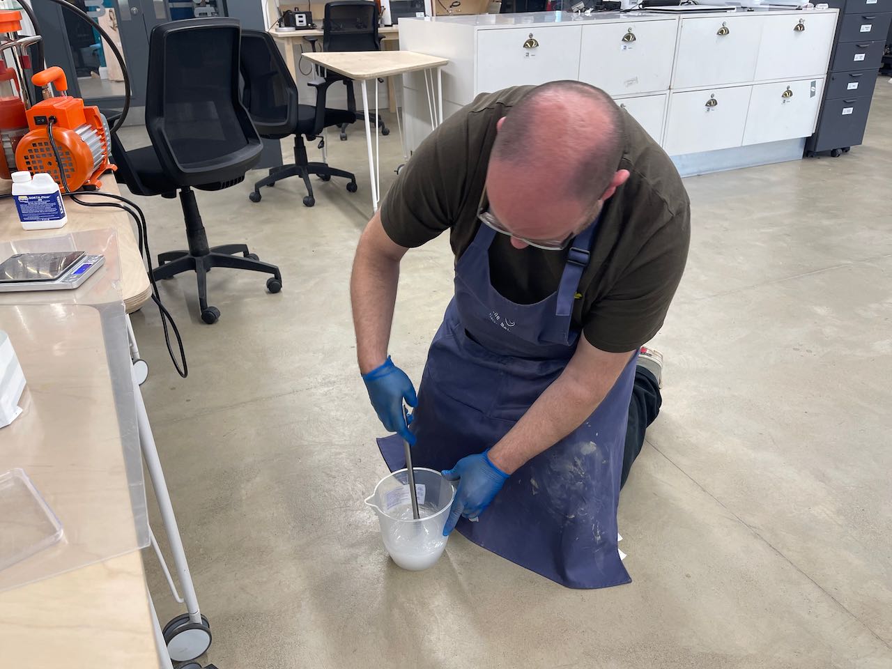
Now time to assemble the moulds, tape them up and mix the silicone following the info on the data sheet, weighing accordingly starting with part A first then part B.
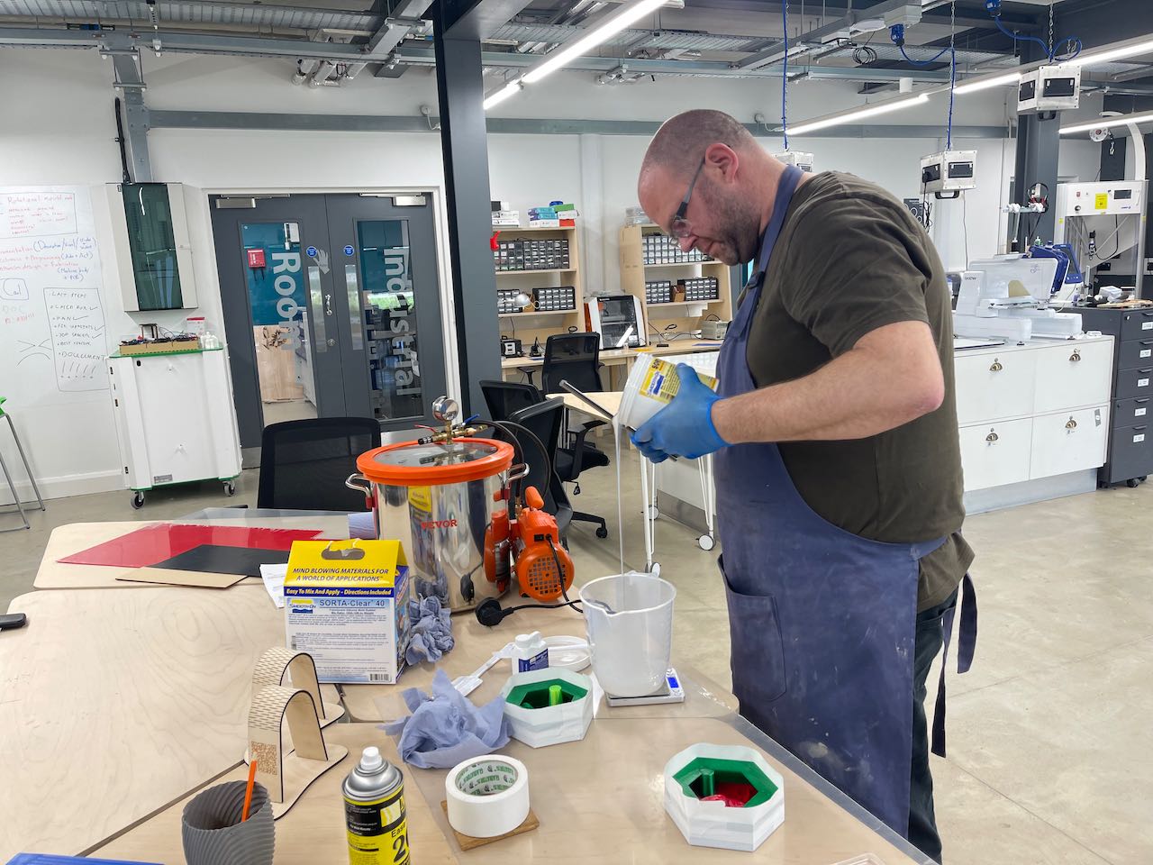
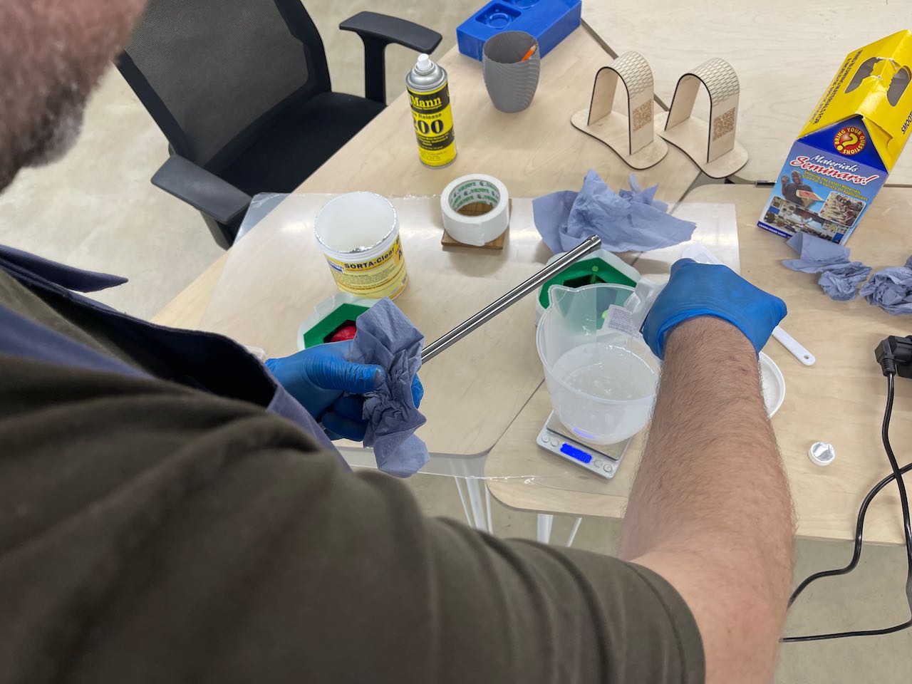
Once the two parts have been added it's time to mix - I used one of the steel rods from the Ultimaker we disassembled to make the rotocasting machine - be sure to clean with IPA or similar and mix thoroughly for 3-5 minutes.
Place in the vacuum chamber to degas - this takes approximately 15-20 minutes. Make sure you keep an eye on it so it doesn't rise over the edge of your container (I should have used a bigger container as I had to vent a few times which increases degas time).
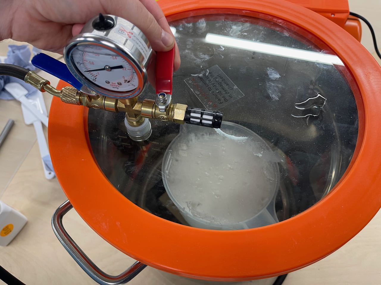
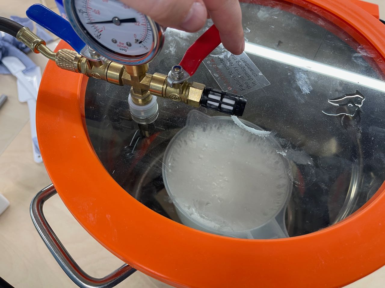
The silicone will collapse in the container after this happens. Let it degas for a further 4-5 minutes.
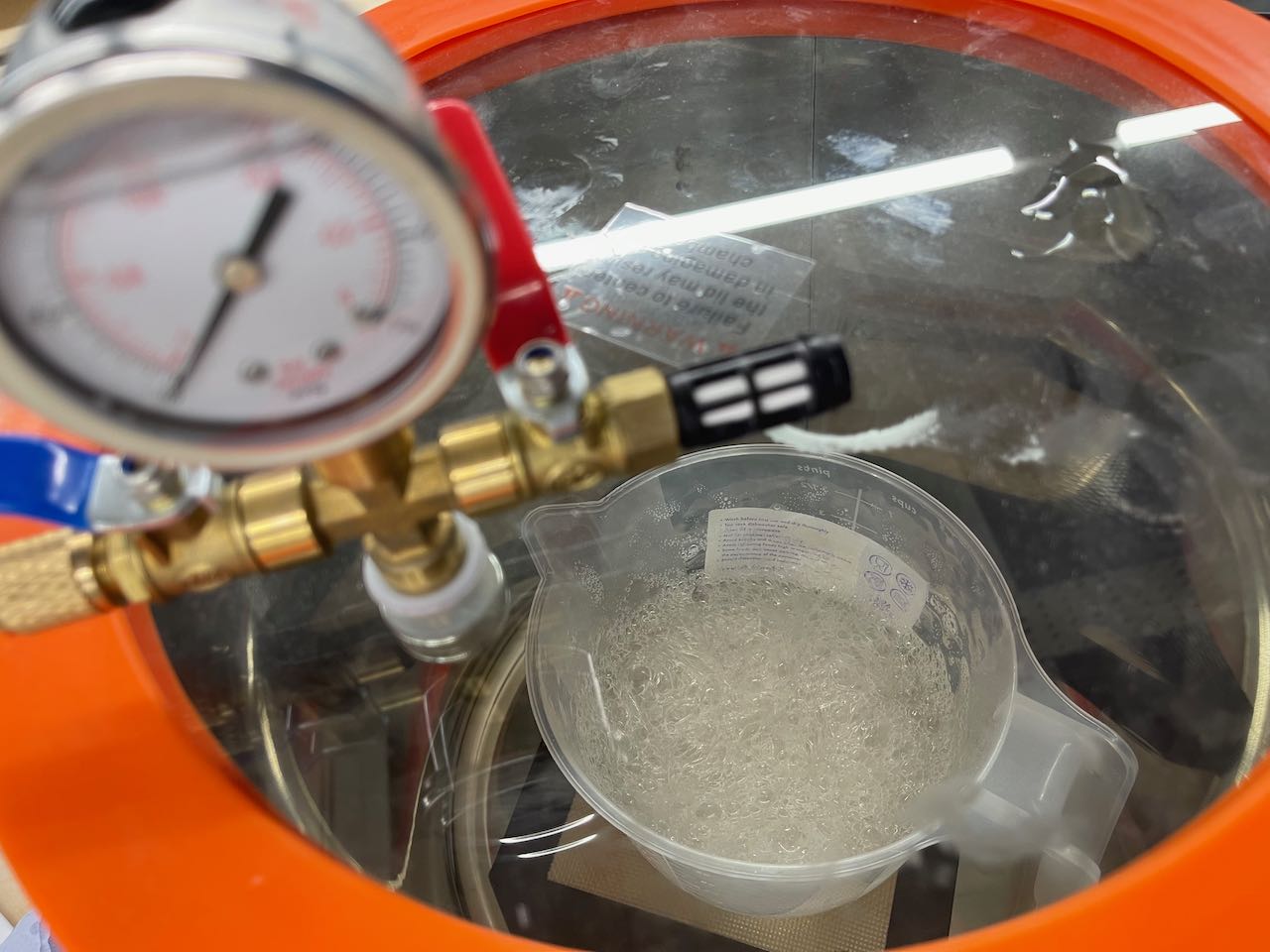
We can now vent the vacuum chamber, lift the lid and begin to pour our silicone moulds - when pouring it's good to pour from a height in a thin slow stream.
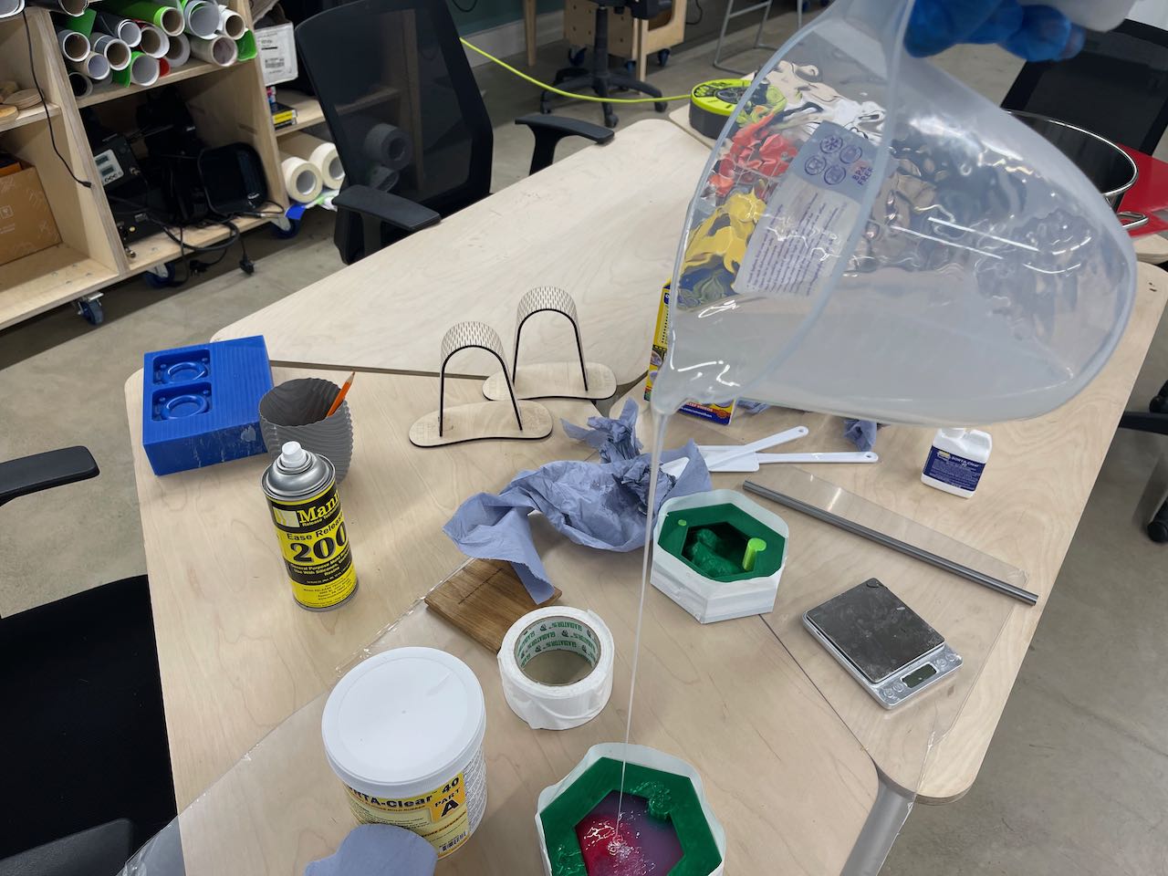
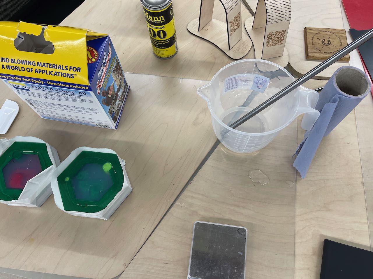
The two moulds filled and set aside to cure for 24 hours - I leave the mixing container to cure before cleaning as it's easier to clean.
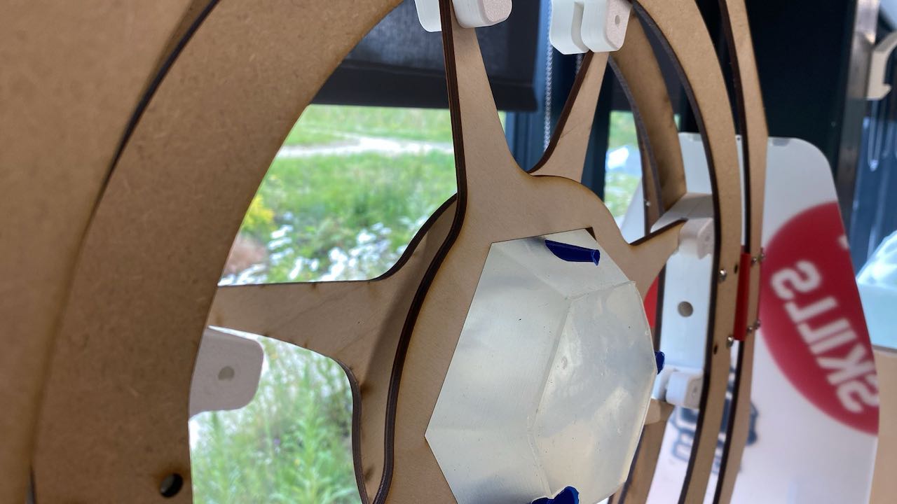
Below are some images of the moulds in the rotocasting machine.
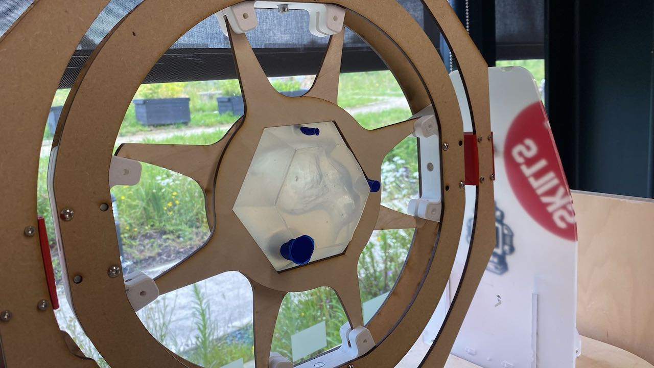
Due to time restrictions this week I was unable to cast the parts - I will get it sorted soon.
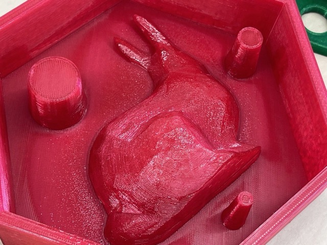
I did manage to cast the back mould with some alginate - image below.


Issues I've Encountered
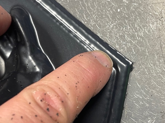
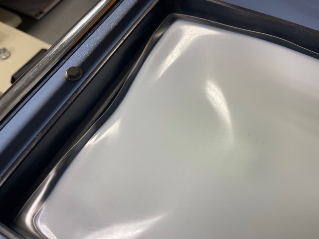
AGHHHHH!
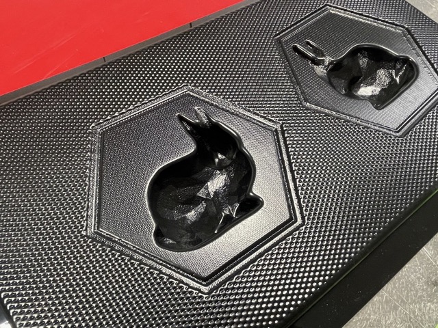
What went wrong? I had a blow out when applying the vacuum - the sheet wasn't big enough to be clamped properly - see images below.
I would advise not trying to use the blow torch to smooth the layers on the PETG printed parts - it was not effective.
I would advise something like Smooth-On XTC for this.
Learning Outcomes
Summary of Learning Outcomes
During Week 13, I gained hands-on experience with the complete process of moulding and casting. I learned how to design and prepare 3D models for both vacuum forming and silicone moulding, including optimising models for manufacturability and material efficiency. I developed practical skills in using vacuum forming and rotocasting equipment, as well as in handling and mixing casting materials safely. I also learned the importance of registration features, surface finishing techniques, and troubleshooting common issues such as leaks and poor mould alignment. This week reinforced the value of careful planning, iterative design, and attention to detail in achieving high-quality cast parts.