Week 08. Electronics Production
Machining PCB's and soldering tiny components to make things work...
Assignment
Group Assignment (link):
- characterise the design rules for your in-house PCB production process- submit a PCB design to a board house
individual assignment:
- make and test a microcontroller development board that you designed- extra credit: make it with another process
Making a microcontroller development board
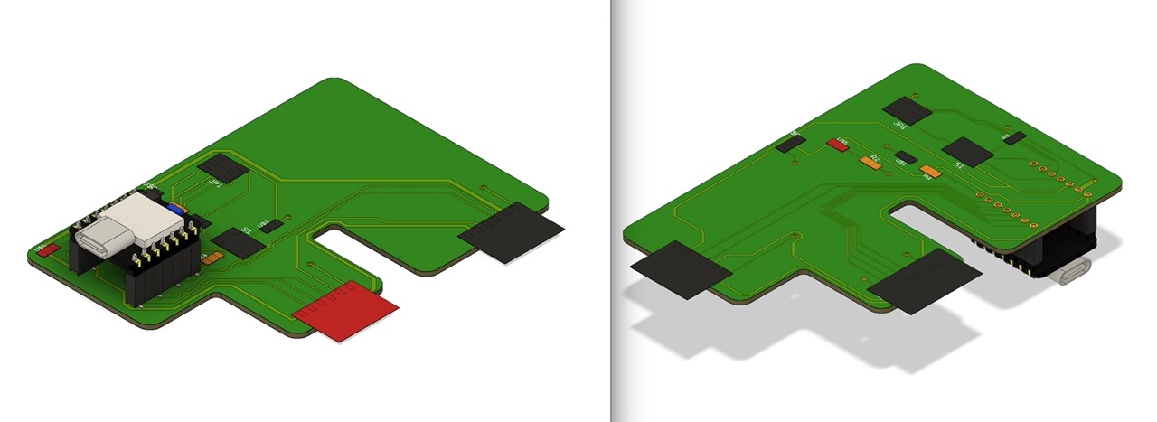
The plan was to produce the PCB board I designed in week 6.
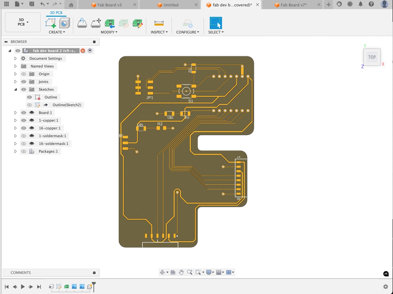
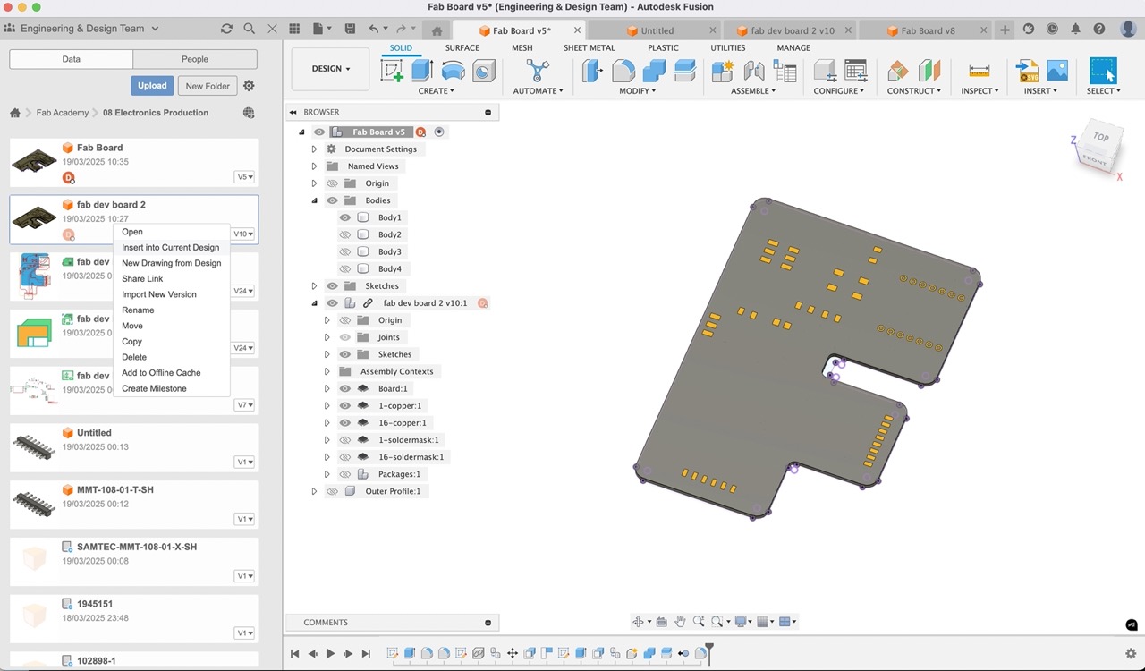
However, I had some design changes that needed to be made to accommodate the components I had to hand. So it was back to Fusion and electronics design workspace to make the changes. I copied the original design into a new folder for week 8 in my Fusion Academy project in the Fusion Hub. Here is a screenshot of the original design and the one with the changes I made.
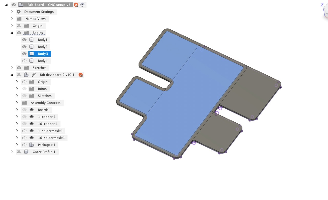
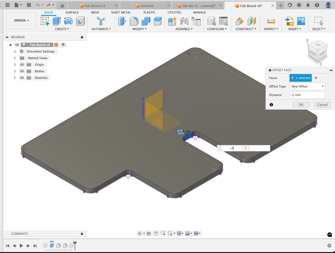
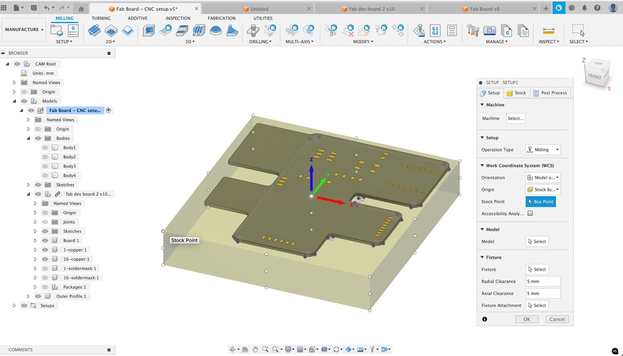
It was now time to set up for CNC milling. I inserted the design into a new file in Fusion - this seemed easier than working in the 3D PCB workspace as I wanted to customise the outer profile to allow for a Board Flip - I wasn't able to make a single-sided PCB. This new file would allow me to create a Board flip that would hold the board in place when machining the back. I copied and pasted the F as a body in the document and flipped it. I then created a new sketch and offset it by 2mm (the diameter of the cutting tool I would be using to machine the profile of the board). This would allow the F board to be held in position when machining the back. I also adjusted a portion of the F so it would grip the back of the board when machining.
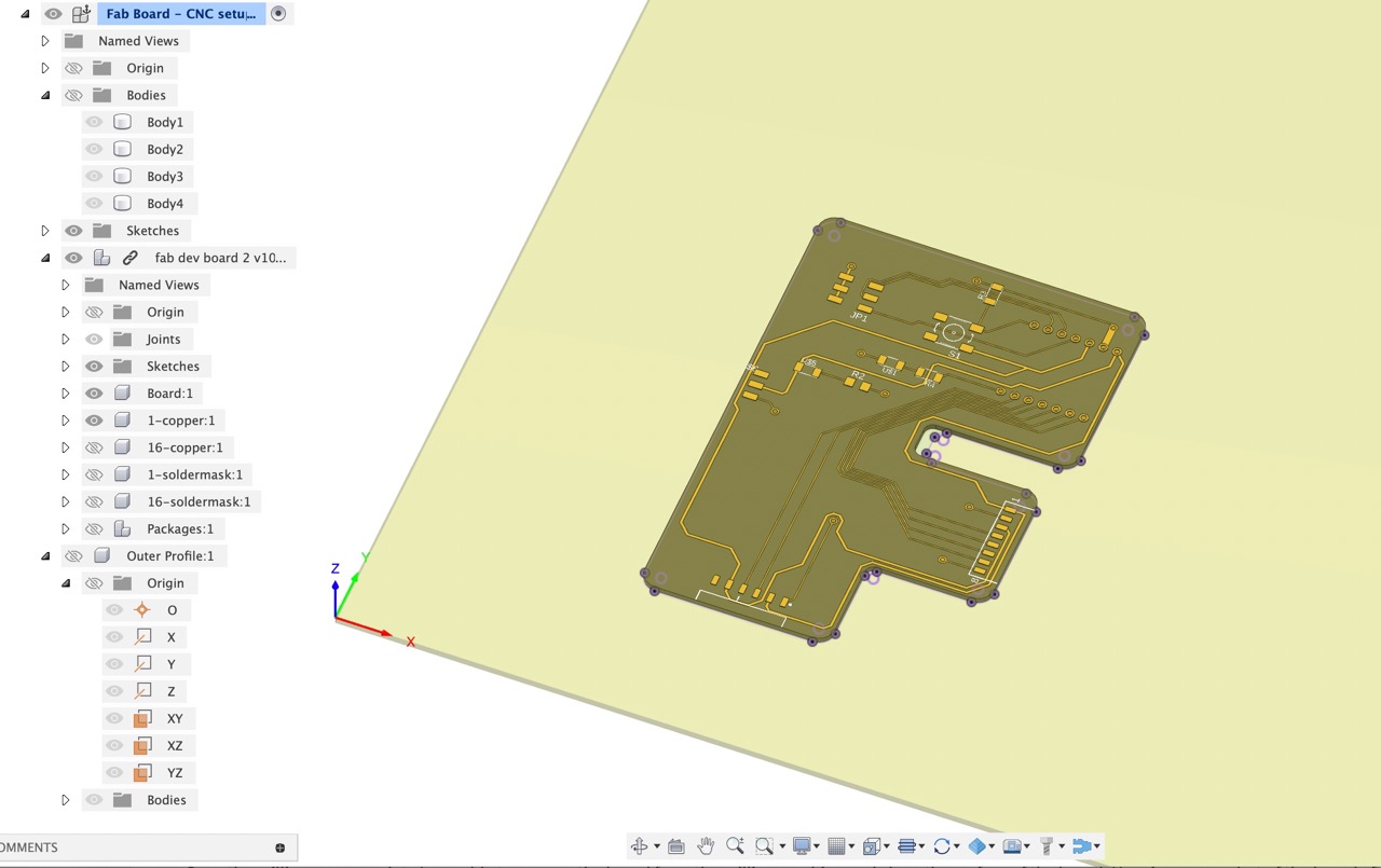
Back in the 3D PCB model we see the component is out of date - click the icon in top left of the screen to update.
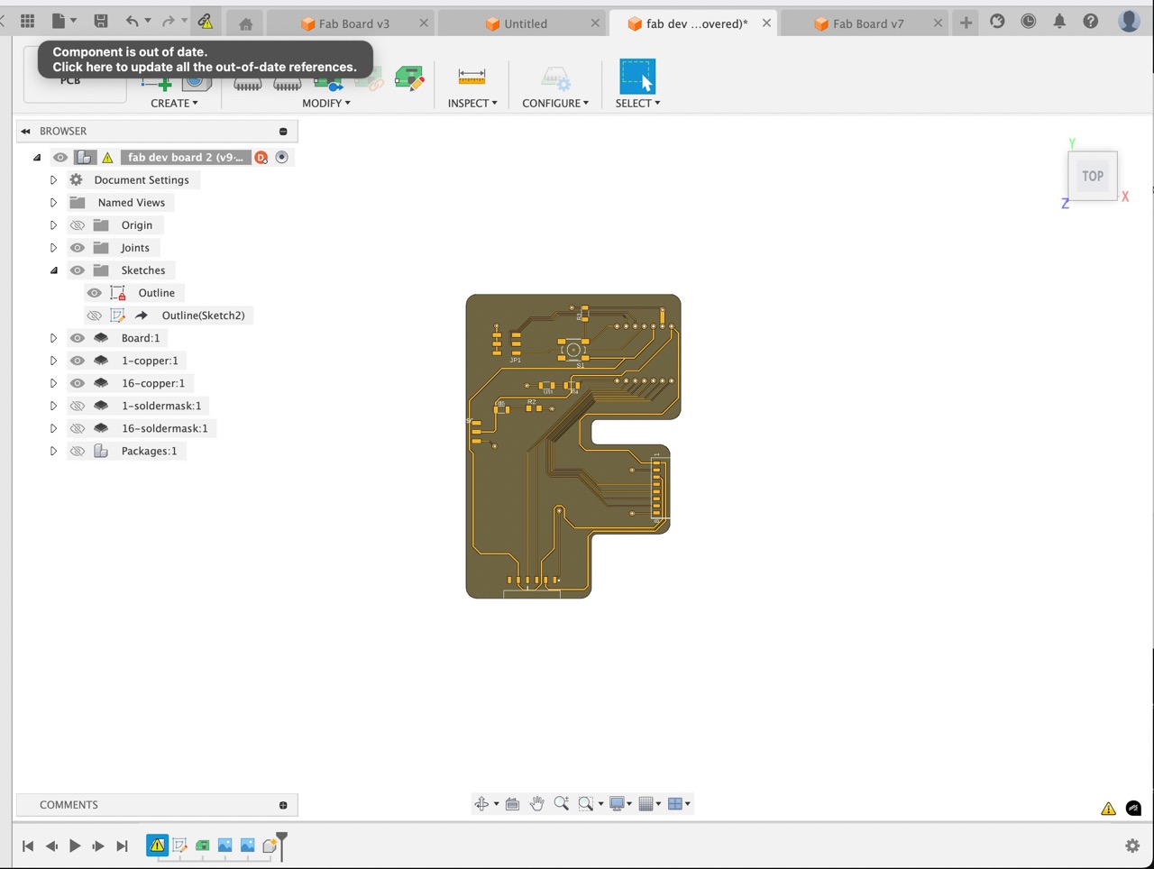
All components should update to the latest version
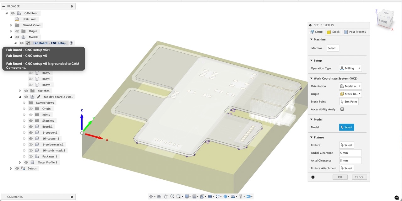
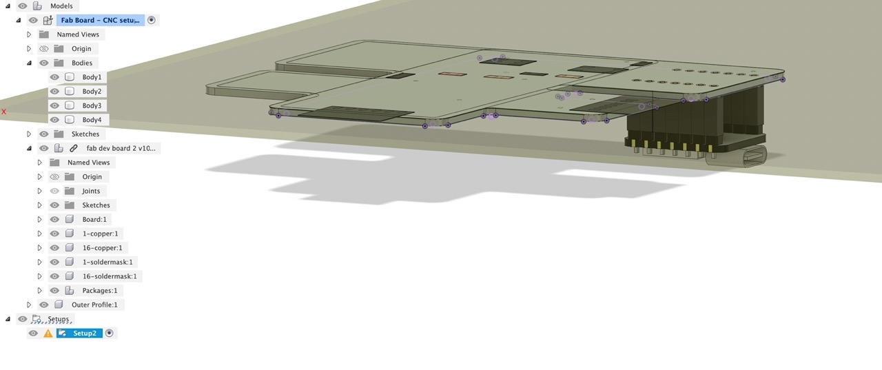
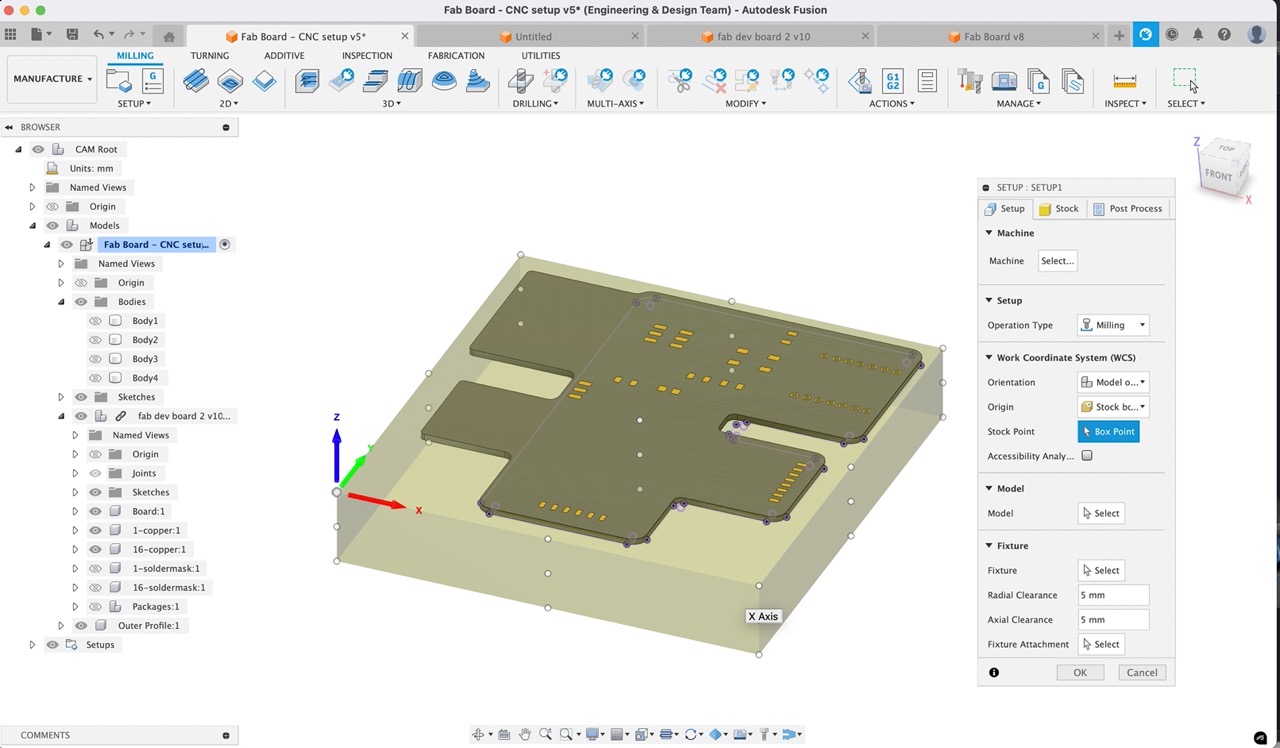
Back in the CNC set up file I created we can switch to the Manufacture workspace - Create a new Milling Setup.
Set stock to fixed box size - set it to the size of the stock we plan to use
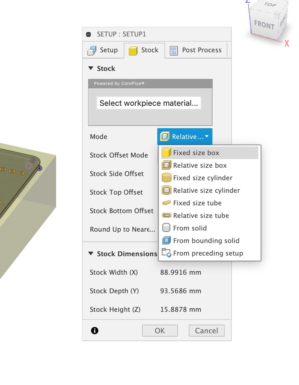
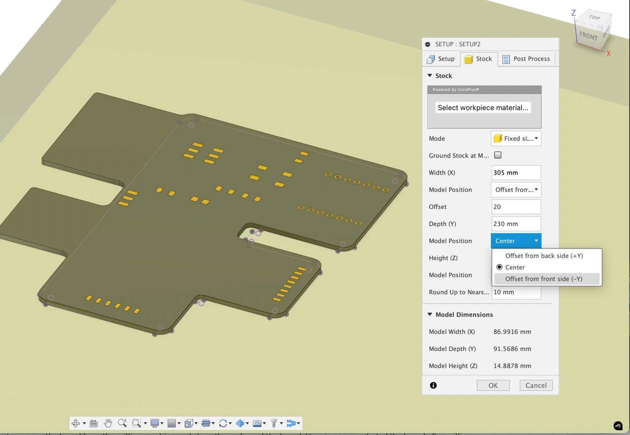
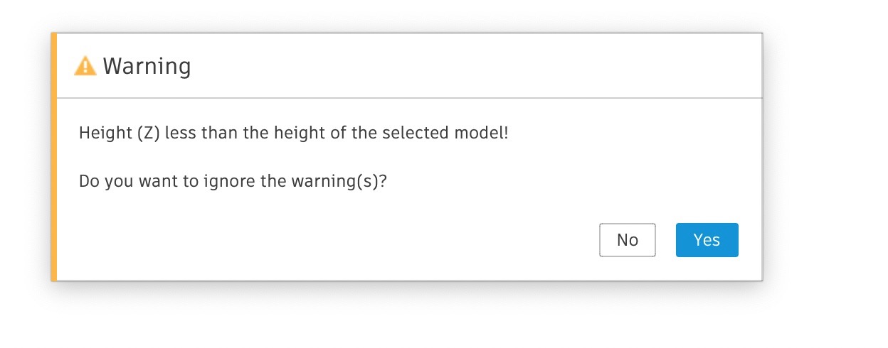
We need to offset the stock from the top of the board (If I selected the model properly in the previous screen just selecting the parts of the board I'm looking to machine I might not be getting these errors)
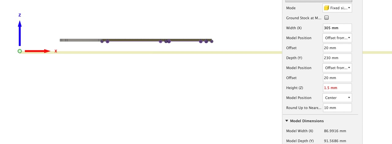
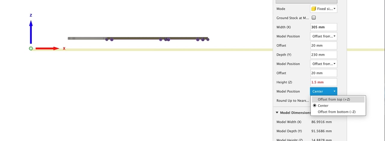
This is me setting the offset to get the stock into place
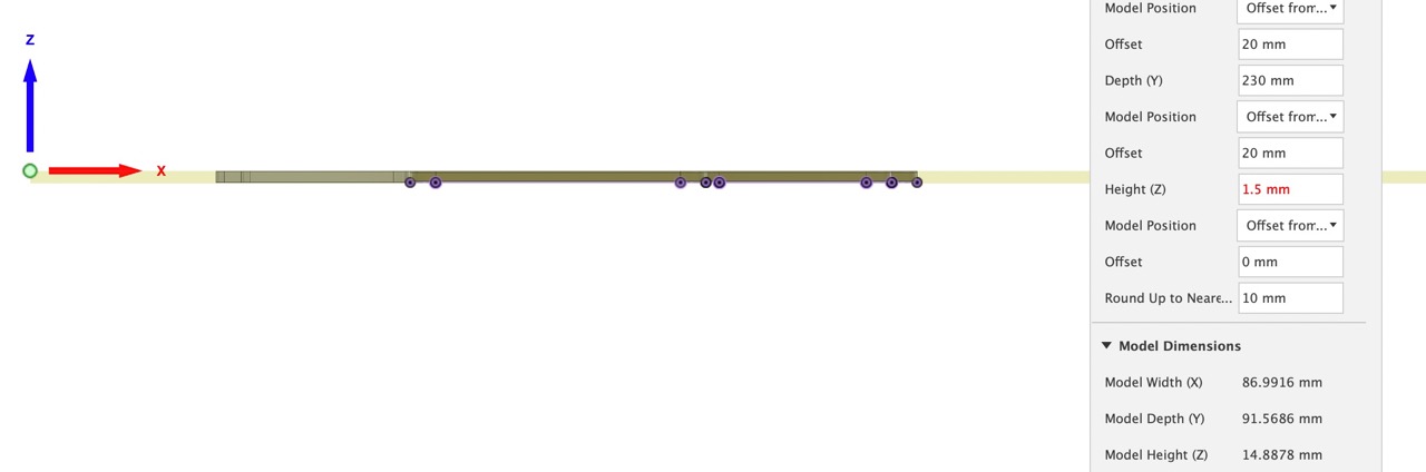
I click yes to ignore this warning (but again if I selected only the model bodies to machine in the previous tab I might not have encountered this error)
Confirm the Origin is located in the correct position - with X,Y,Z, point in the correct direction - go back to setup if not and select the WCS box point and pick the point on the stock where you want to set the origin (it should match the image below)
The videos below show the stock setup process
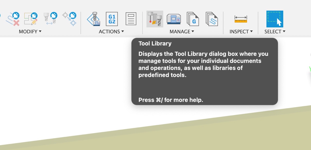
Once we have the stock set up we can now start setting up the tool paths - but first we need to set up some tools using the tool library. This can be accessed to the right of the ribbon/menu bar in the manufacturing workspace
We need to create the tools we will be using for this - they are not provided in the Fusion Library (that I can see anyway)
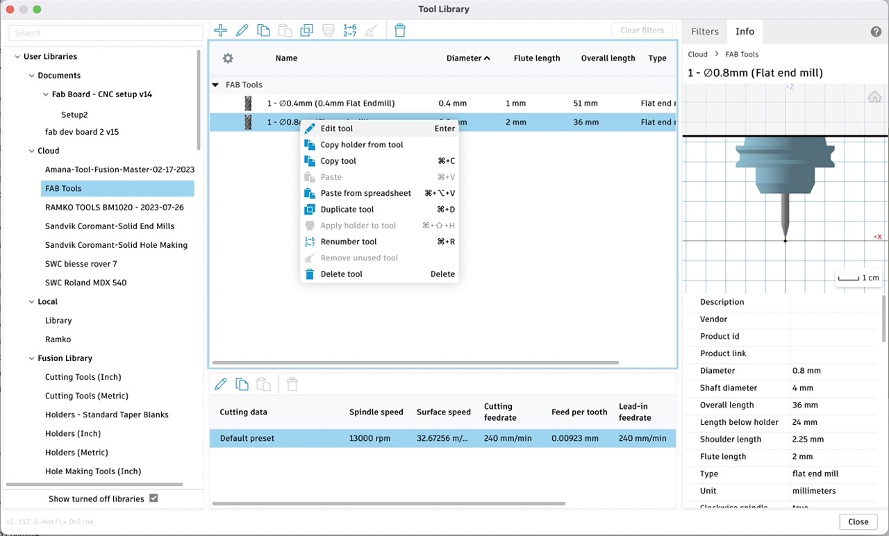
I have exported the tool library if you would like to use them as a base point - you will need to check your feeds and speeds however - don't trust the defaults I have set
First set up a new cloud library (you can create a local library either however I recommend creating a cloud library as it will move with you if you log into Autodesk Fusion on multiple computers)
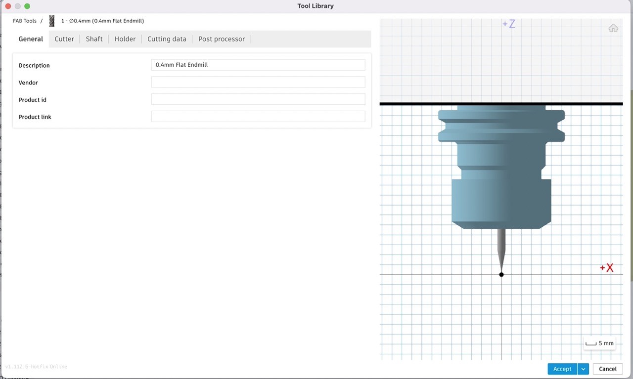
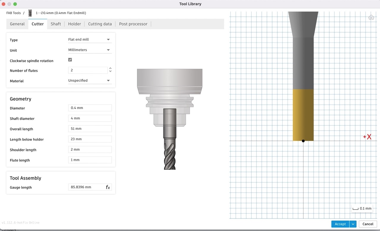
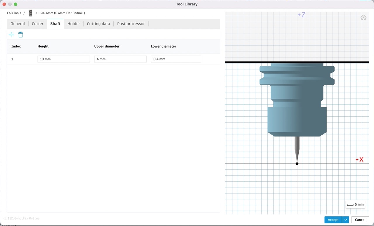
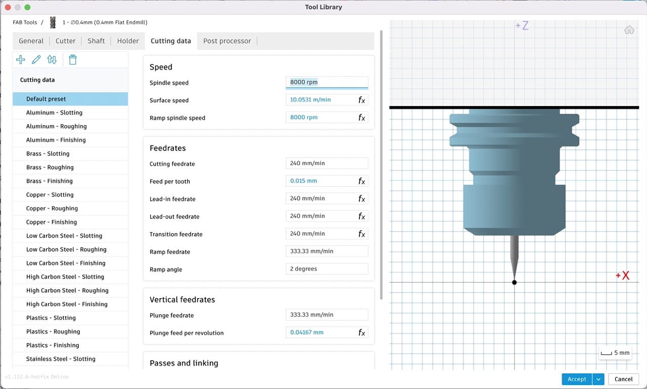
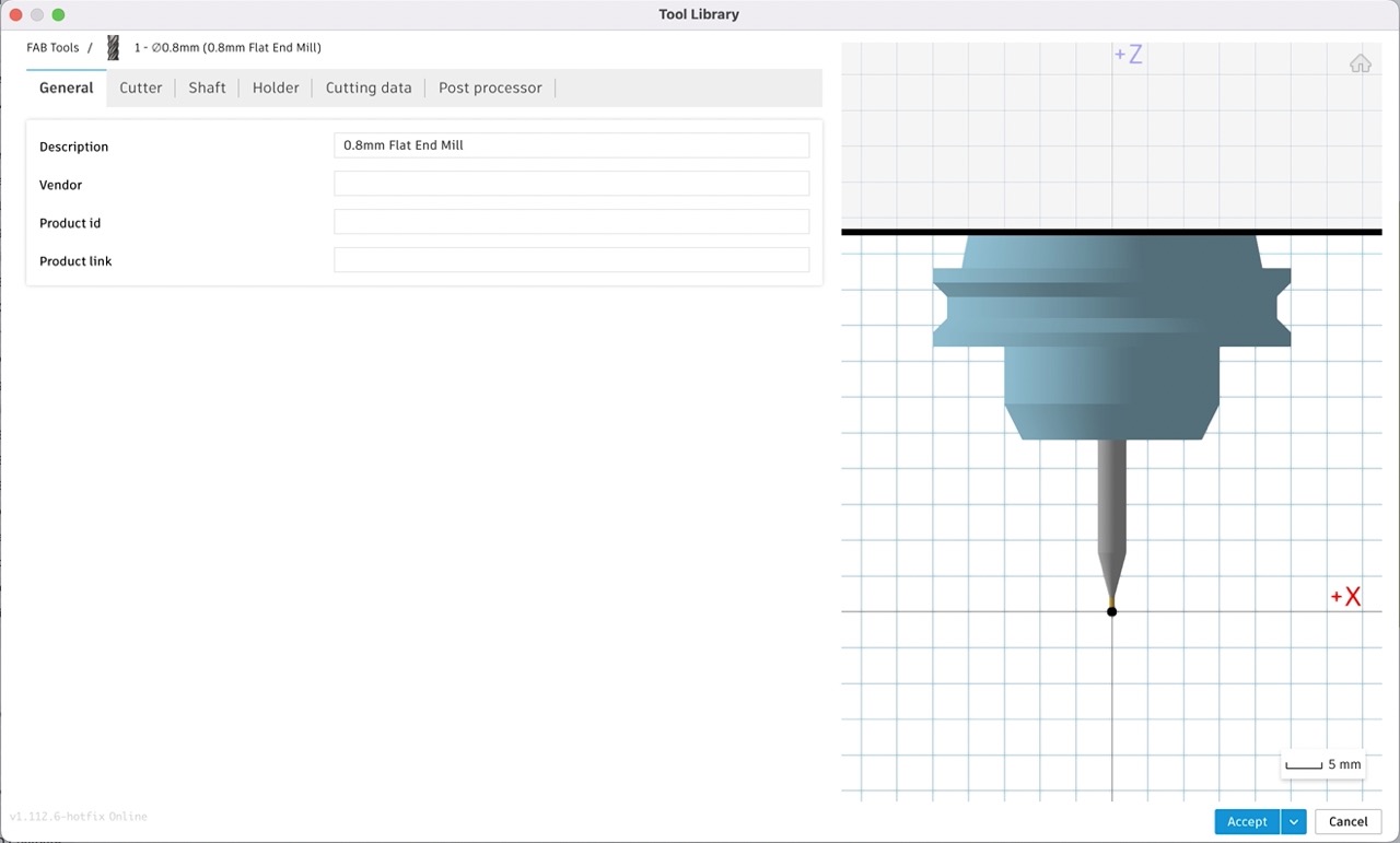
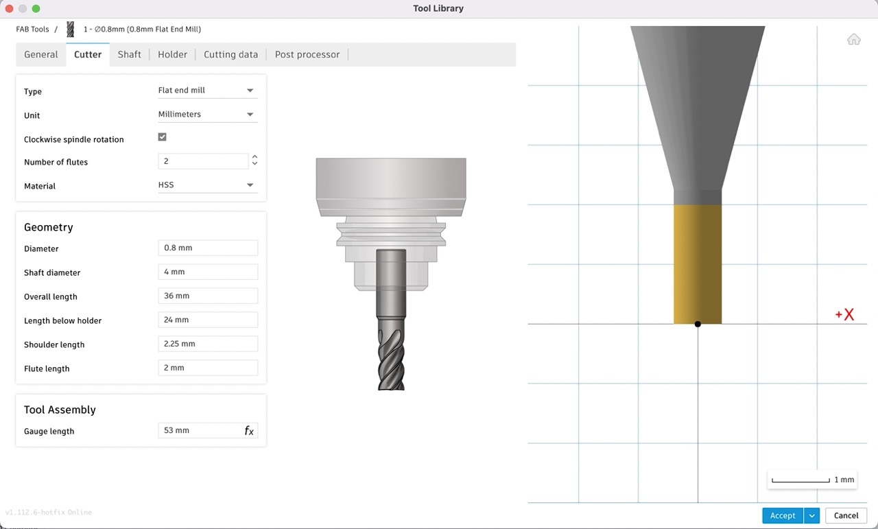
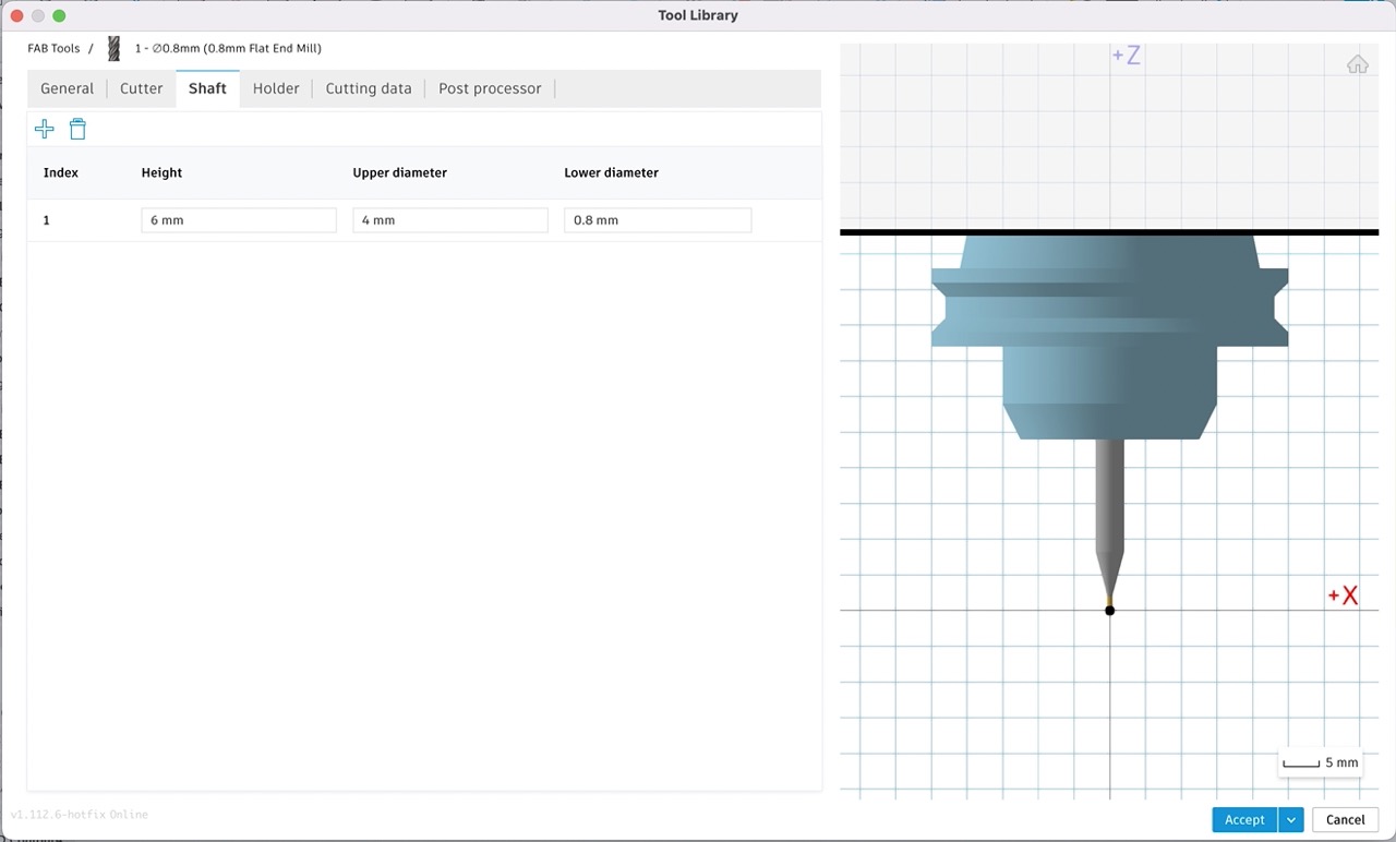
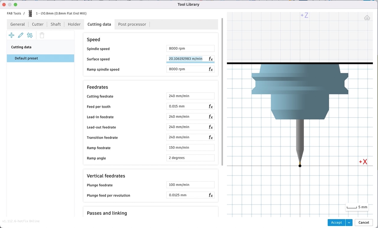
Next use the + icon to add a tool - select the tool type as the basis - in my case it was flat endmill
Work your way through the tabs and input the necessary parameters to set up your tool - you can always come back and edit them after. See screenshots above. I copied/replicated the info from mods for feed rate and depth of cut - but you should check and test these for your setup.
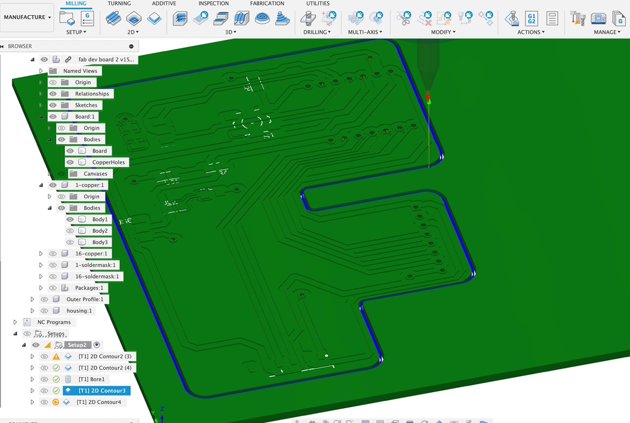
Once happy with the tools I start by setting up tool paths for the traces, holes and board outline.
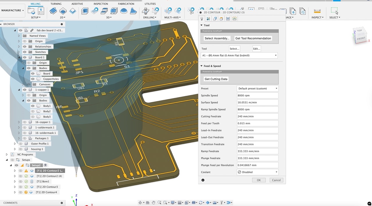
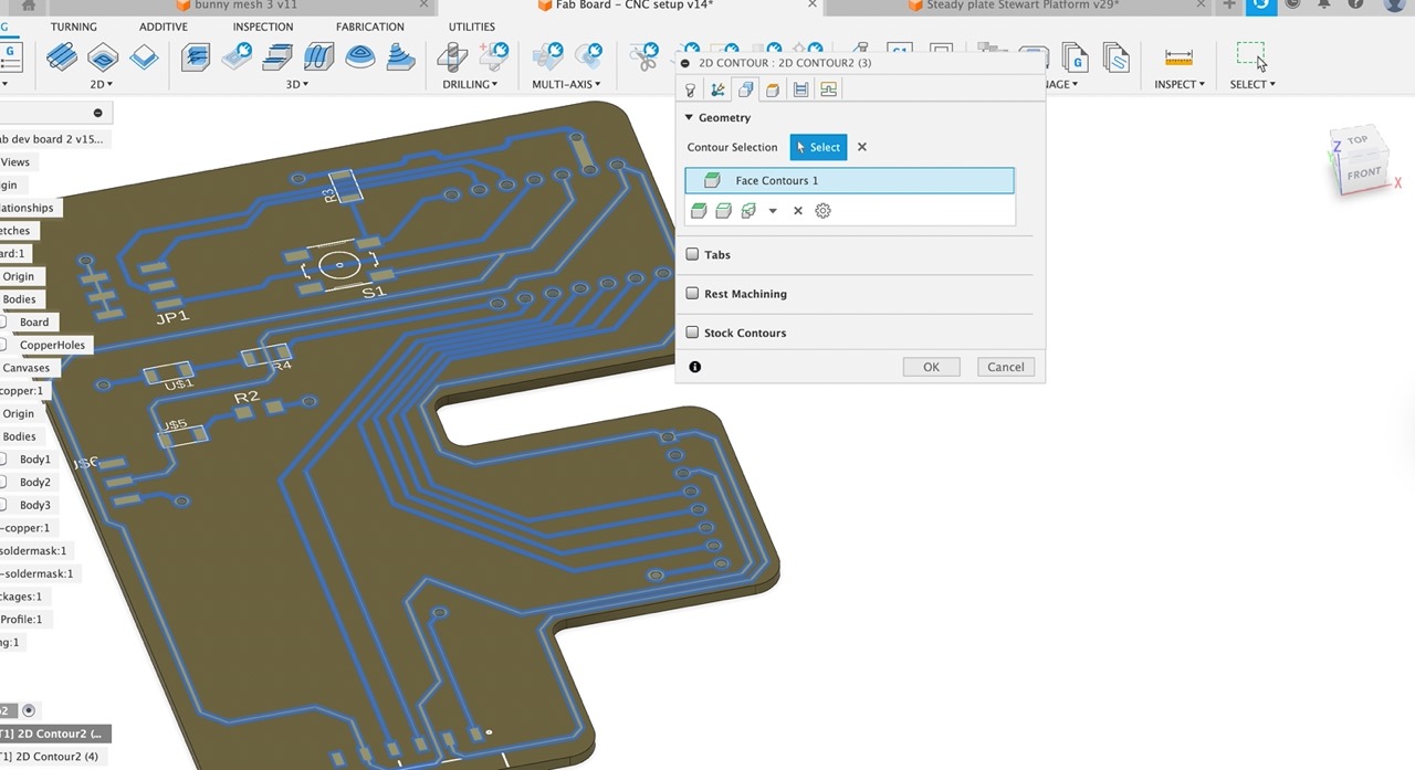
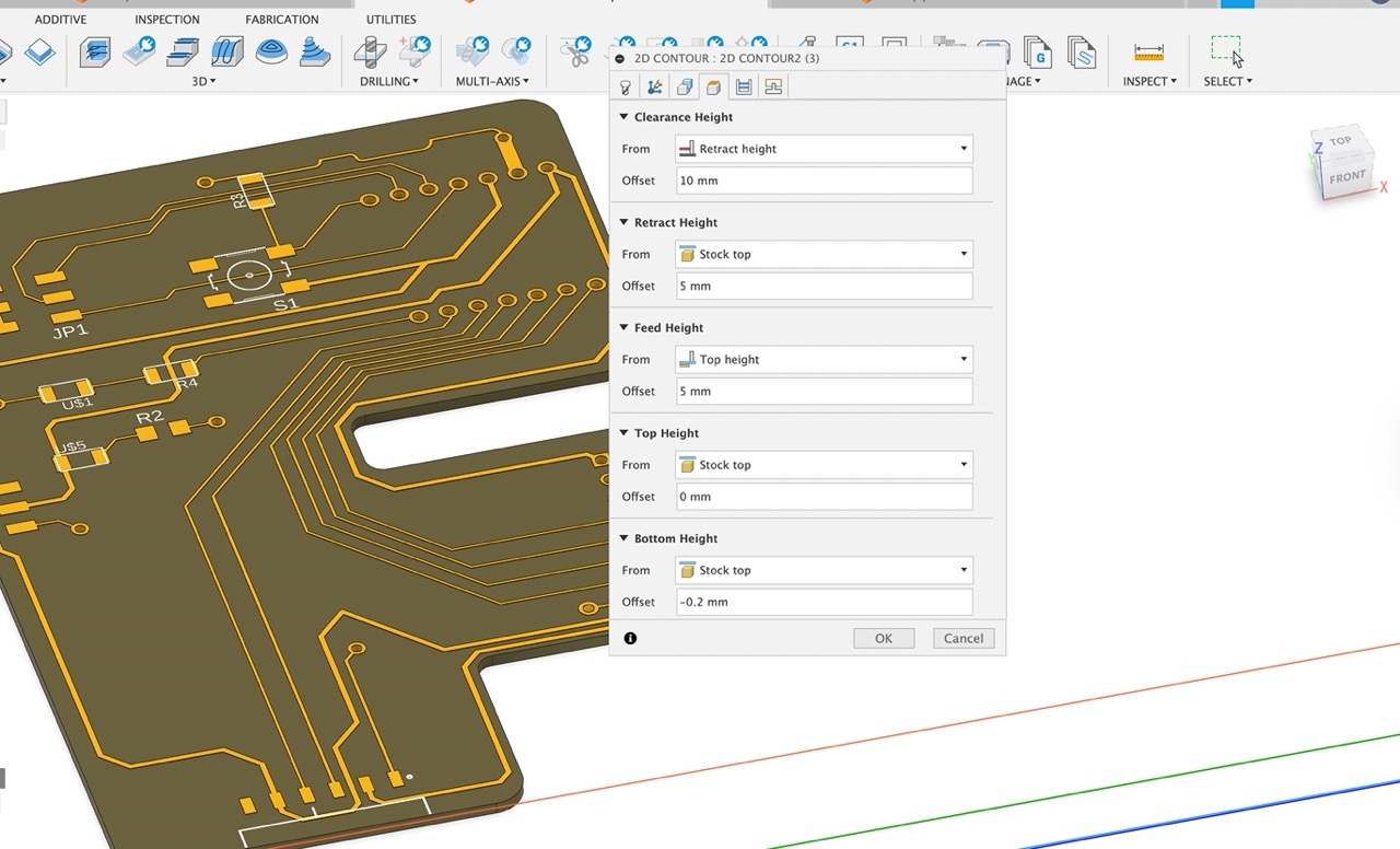
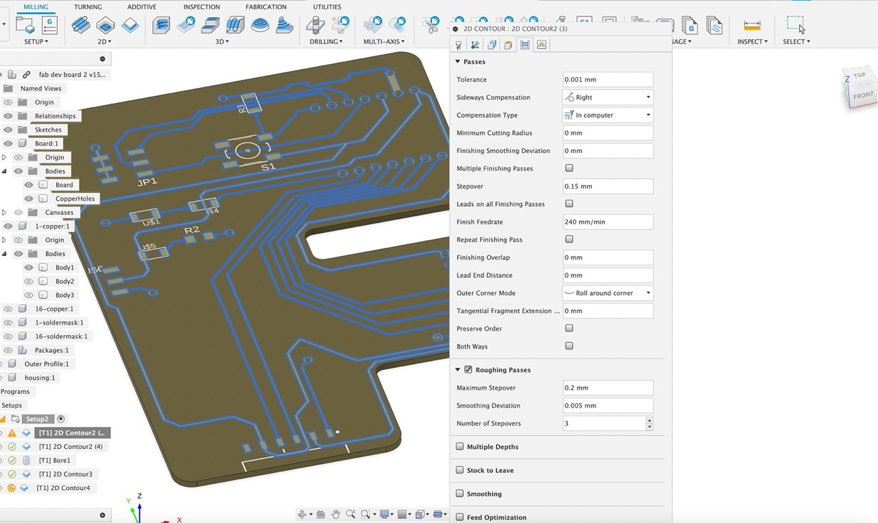
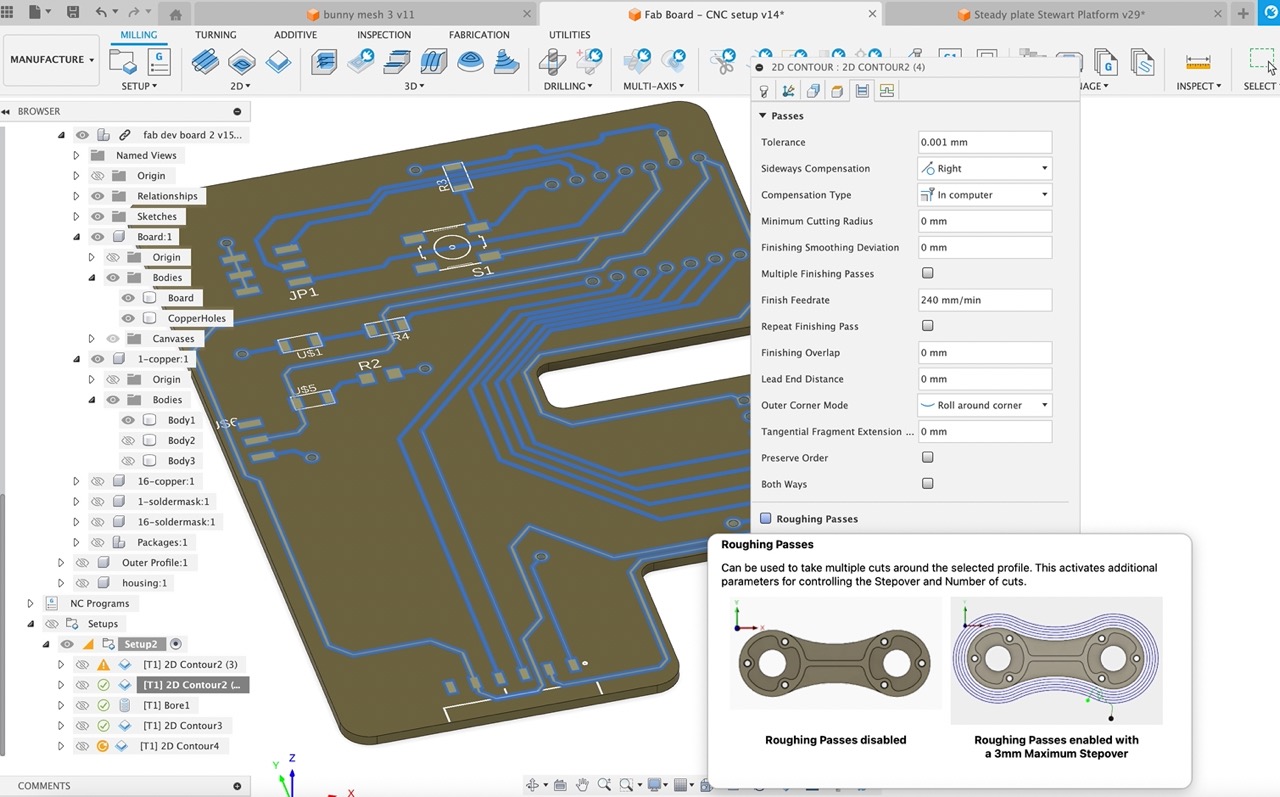
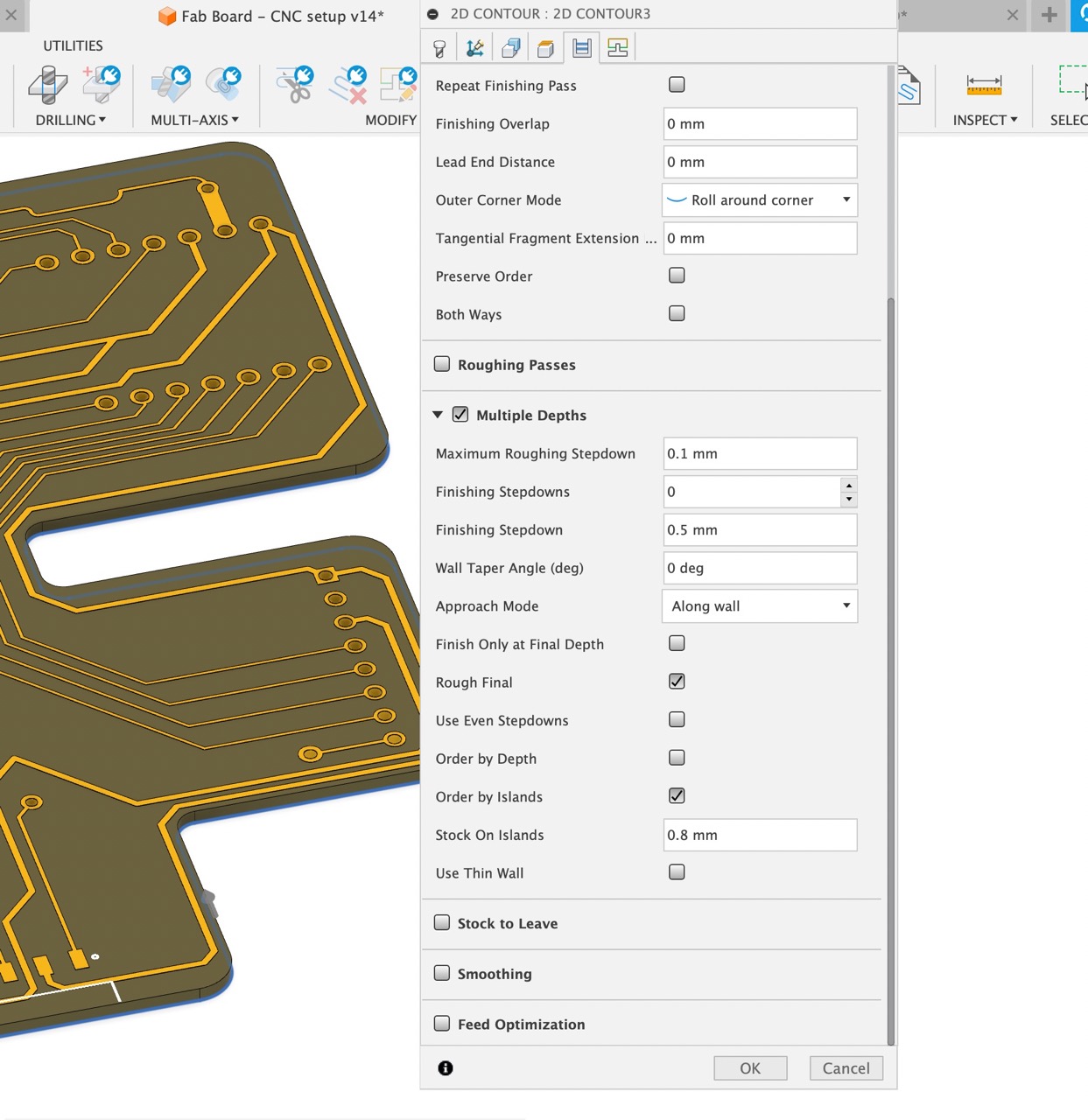
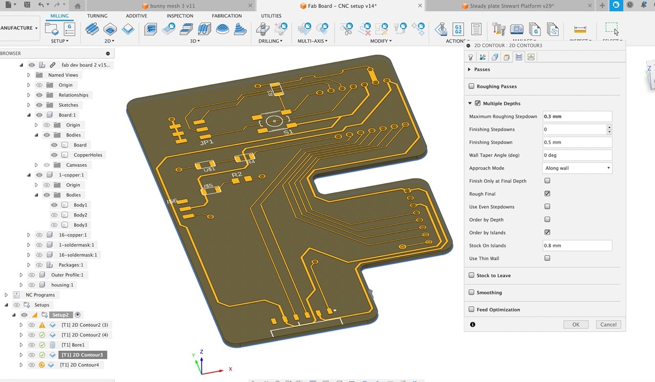
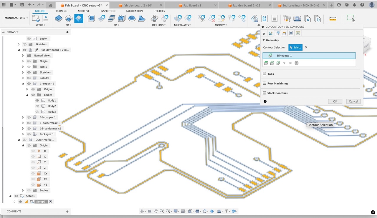
Next we set up our tool paths for cutting the traces - I set up one and select the face profile using the copper body traces from the browser on the left. Note how I am using roughing traces with 3x profiles.
I can then duplicate the profile. This time I just remove the roughing passes with x3 stepovers so I can get tight to the traces.
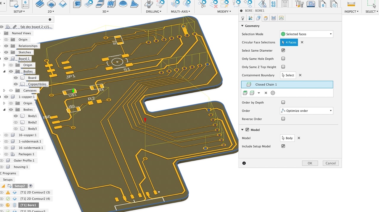
Next I set up the holes - note how I have selected same hole size before selecting the hole wall face - it will select all the same hole sizes automatically saving time - there are 4x different hole sizes to select in this board.
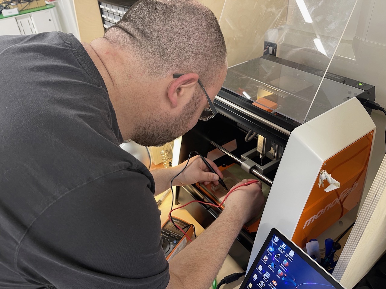
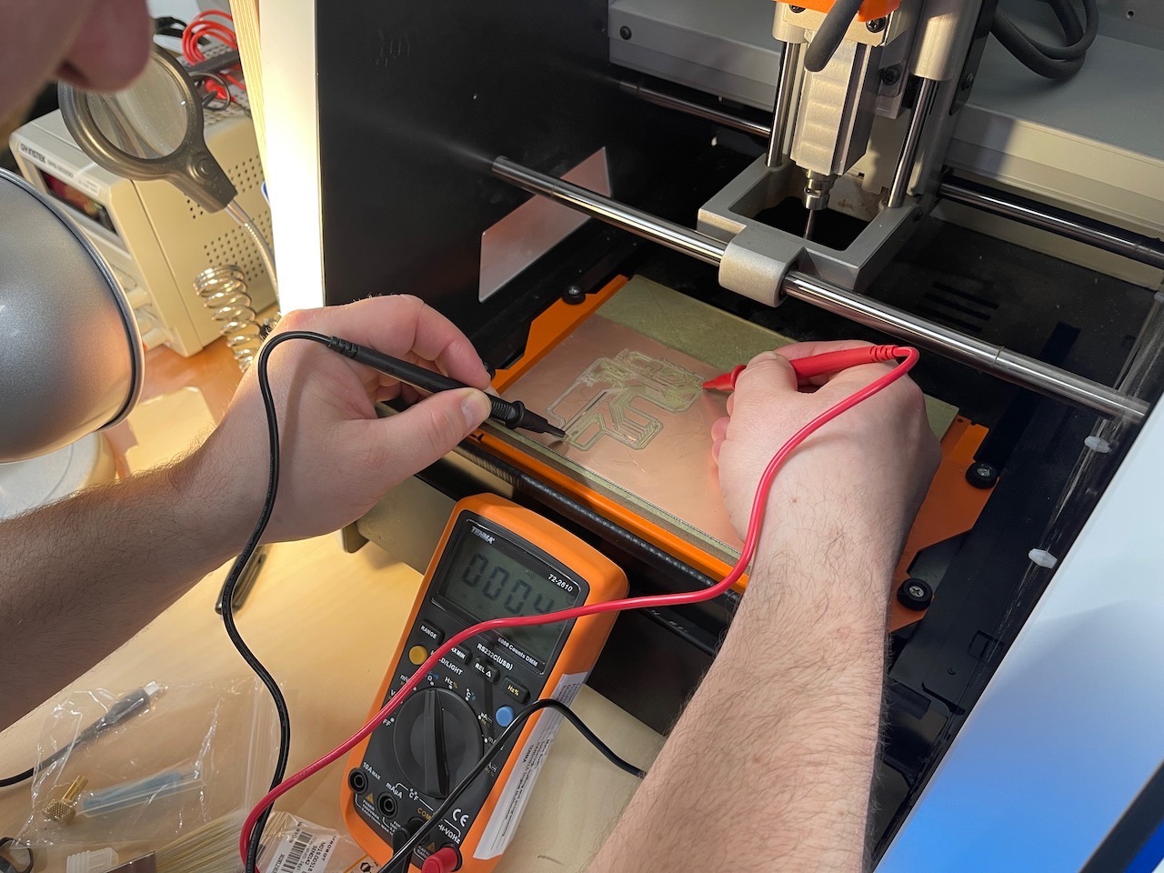
Finally the outer profile. Before I machine this we just check continuity of the traces and make sure there are no shorts.
See the video screen capture below - the process is as followsSelect tool - the 0.8mm flat end mill we just created
Change tab and select hole
Create a new 2D milling profile
If any changes have been made right click on the setup and click generate - this will regenerate the cutting tool paths.
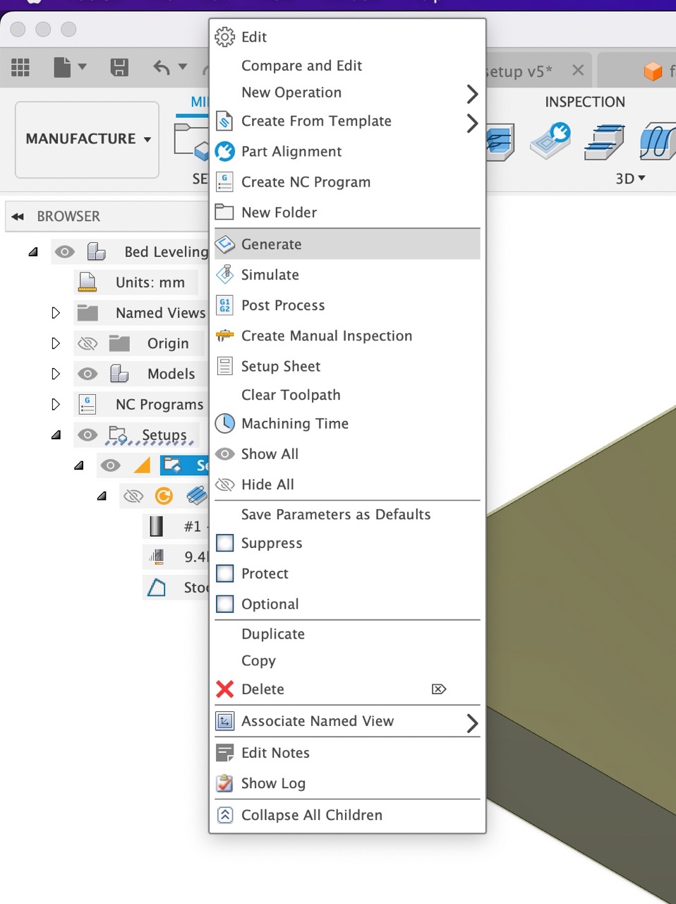
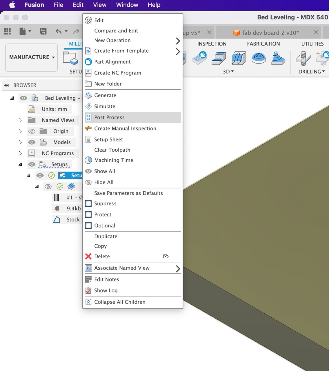
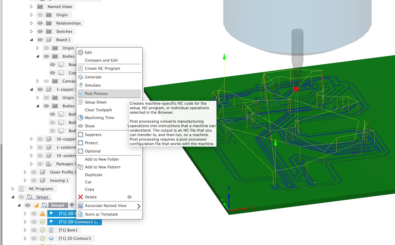
To post process right click on the tool paths you want to output in the browser - you can output the entire setup - this would work if you have a tool changer - for me however I was satisfied outputting tool path setup.
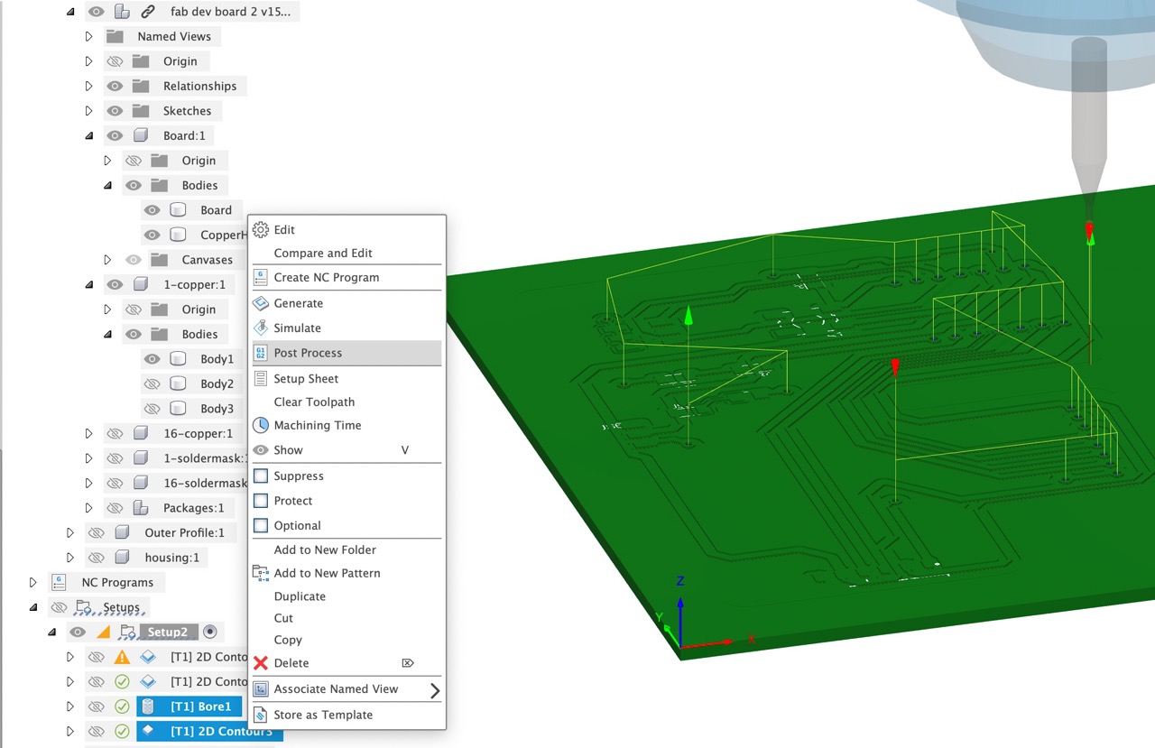
When outputting the files note that I selected the 2x profiles that use a 0.4mm flat end mill and post processed them as one.
I also selected the 2x profiles that use a 0.8mm bit and processed them as one. This minimises the amount of files that need to be post processed however it is perfectly acceptable to post process them individually as well and if it is your first time machining I would highly recommend doing them individually.
After outputing the files from Autodesk Fusion we are able to bring them to the Roland SRM 20 PCB mill - you will notice I gave up on the Roland MDX 540 - I had collet issues, the run-off was too high with an adapter I fabricated - so back down to Creative Spark Fab Lab to CNC the PCB board.
Remove the bed from the mill using the thumb screws on either side
Make sure the surface is relatively clean and smooth - if other board is on there, remove it
Prepare your PCB stock with double-sided tape - cover the entire bottom side of the board - make sure you do a neat job and there is no tape overlap - wait until all tape is on before removing the top protective layer on the double-sided tape.
Fix the stock to the MDF spoil board on the build platform - make sure it is relatively square using the guide lines - use firm force and make sure you get good bond between the board and the MDF spoil board
Place the platform back into the CNC and tighten the thumb screws - make sure it is seated correctly
Open VPanel on the computer - it will need to be connected to the mill to be able to open VPanel.
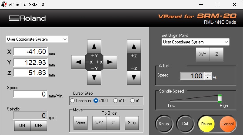
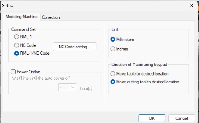
Just to note - I use NC code as I used the Roland ISO post in Autodesk Fusion. If you used Roland RML post you will need to set up for RML - however here it is set to RML/NC. See top right of VPanel where it says RML-1/NC Code.
This can be changed with the setup button - BTW RML stands for Roland Machine Language - its own proprietary GCode language - NC stands for Numerical Control - and is a more open, widely used GCode language - I believe it can also achieve higher levels of accuracy than RML code.
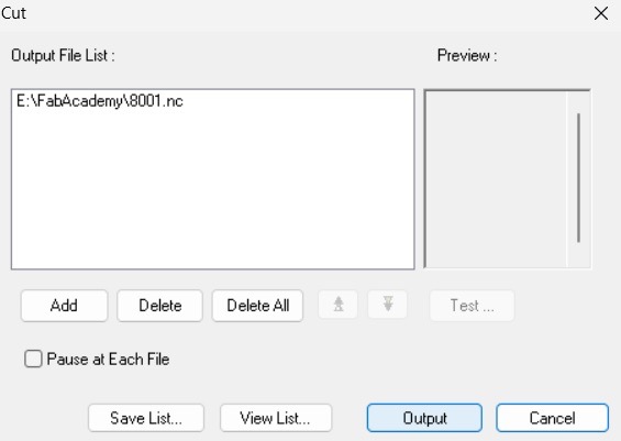
To add our file to process, click the cut button in VPanel - the following dialogue will open - first we need to delete everything that is there using the delete all button.
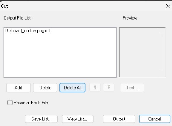
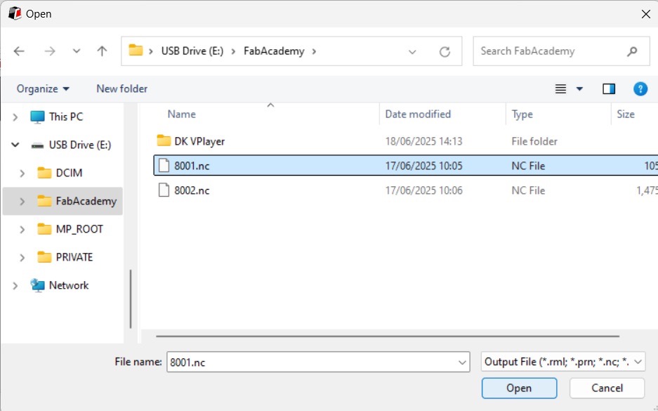
Using the add button we can next navigate to the location where the output file is saved.
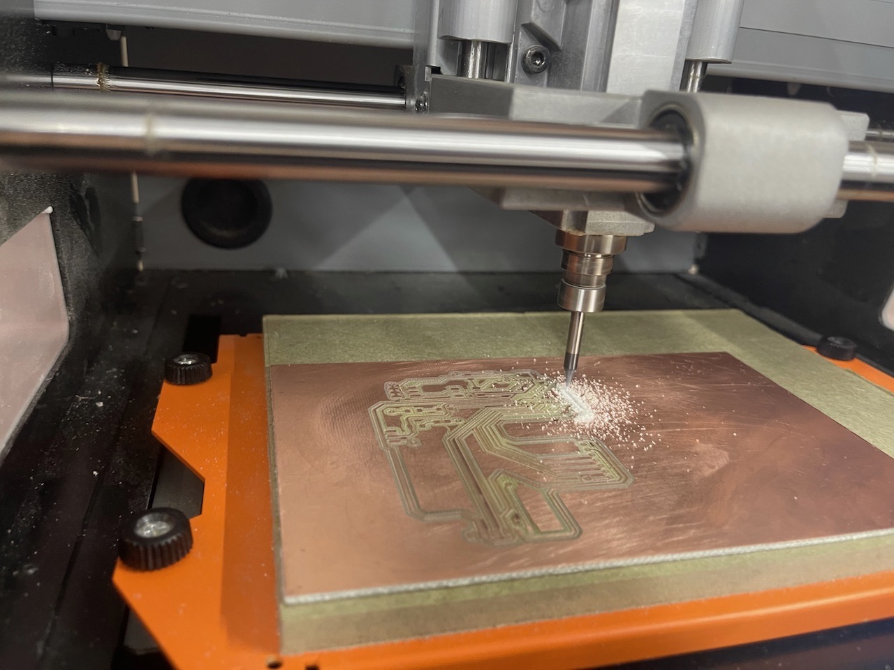
Once selected we can now press the output button - the file will now start machining - as long as the door on the mill is closed.
Set the origin to front left, top corner of the board. This should be the same location as you set it in Autodesk Fusion - Use the arrow keys to move the tool into position --- make sure you have the correct tool in there for your first cut - in my case it's the 0.4mm flat end mill - but I would recommend starting with the 0.8mm or the V bit as they will be less likely to break.
Once in position we can set the X/Y origin and also the Z origin. I would recommend setting Z somewhere in the middle of the stock
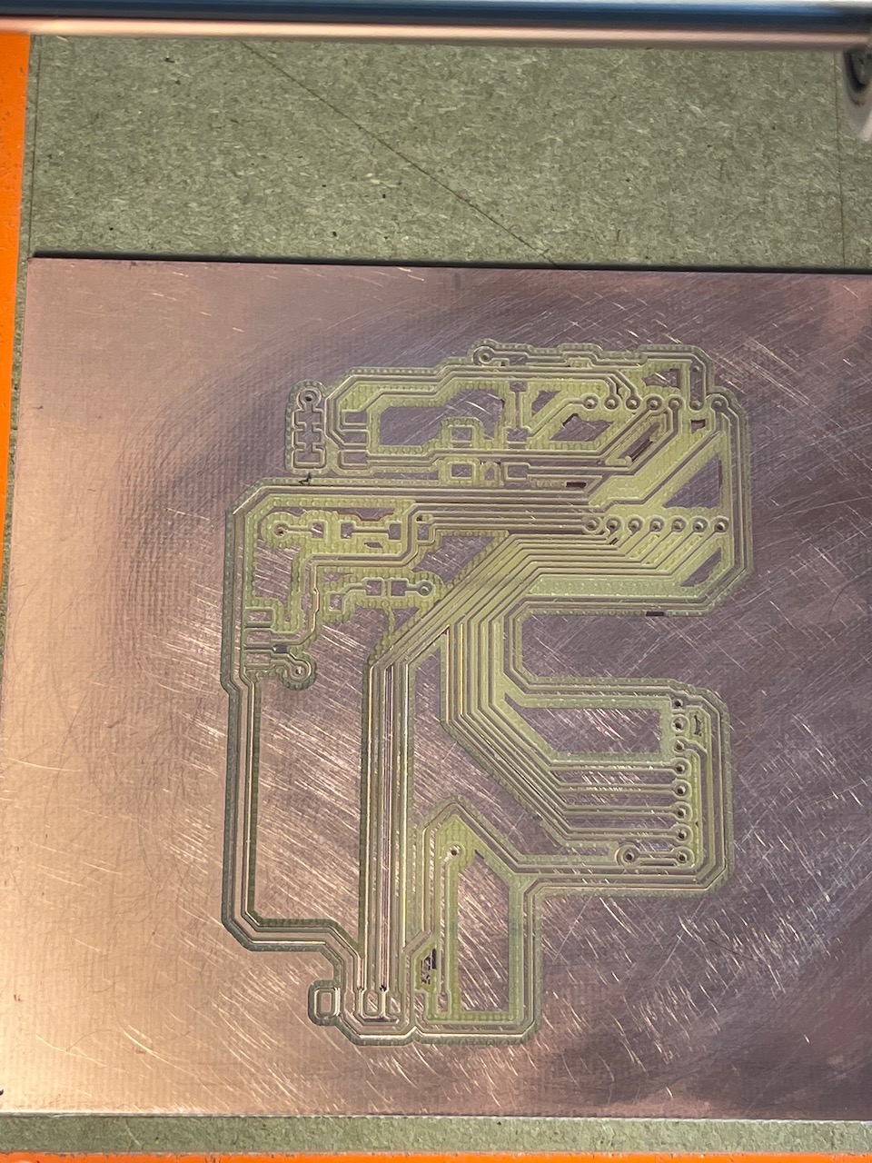
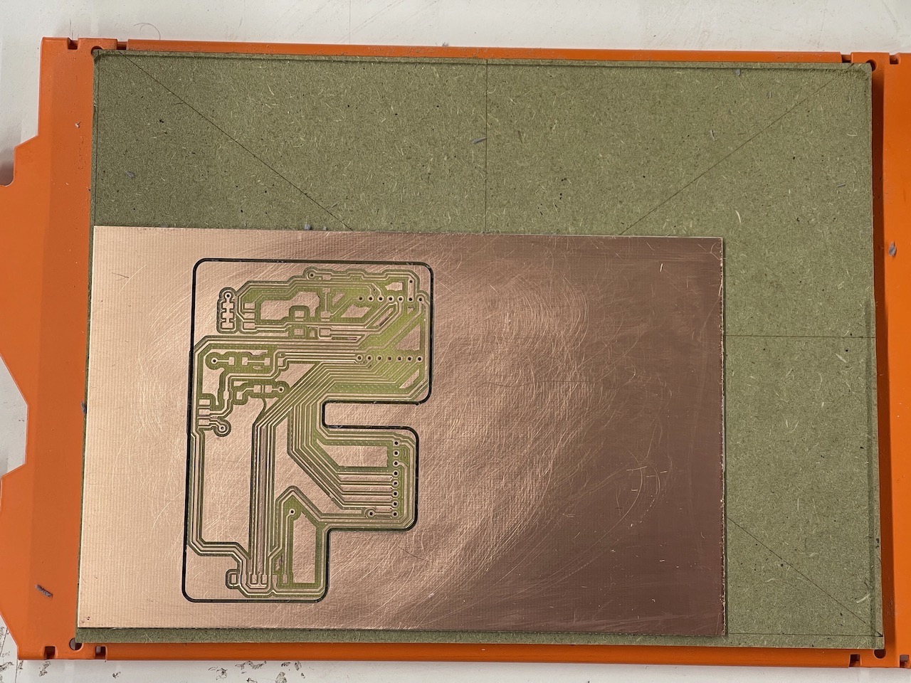
Continuity checking the traces and making sure there are no potential shorts
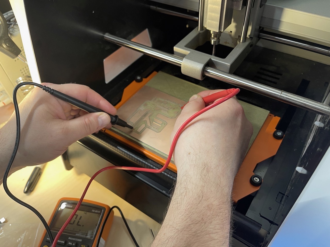
After continuity check we can mill the outline of the board.
Milling the outline of the board
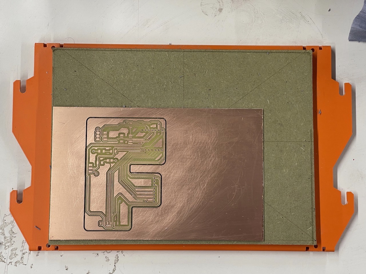
We can now take the build platform out of the mill and remove the board.
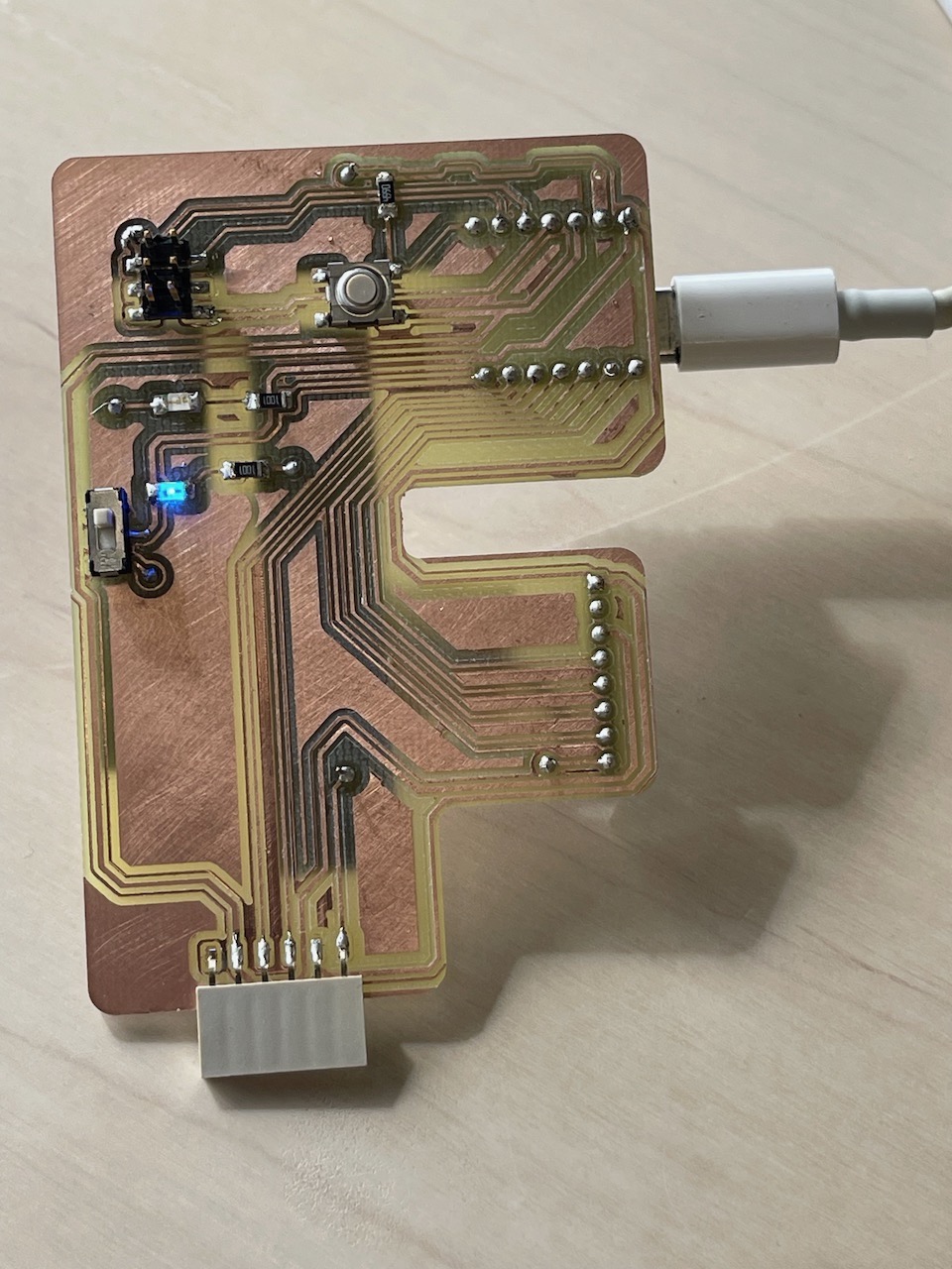
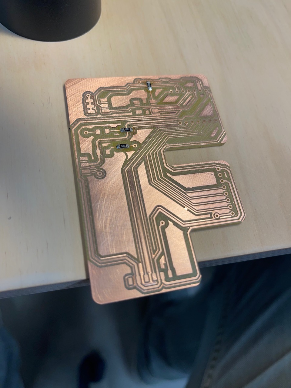
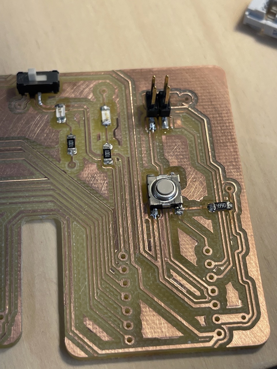
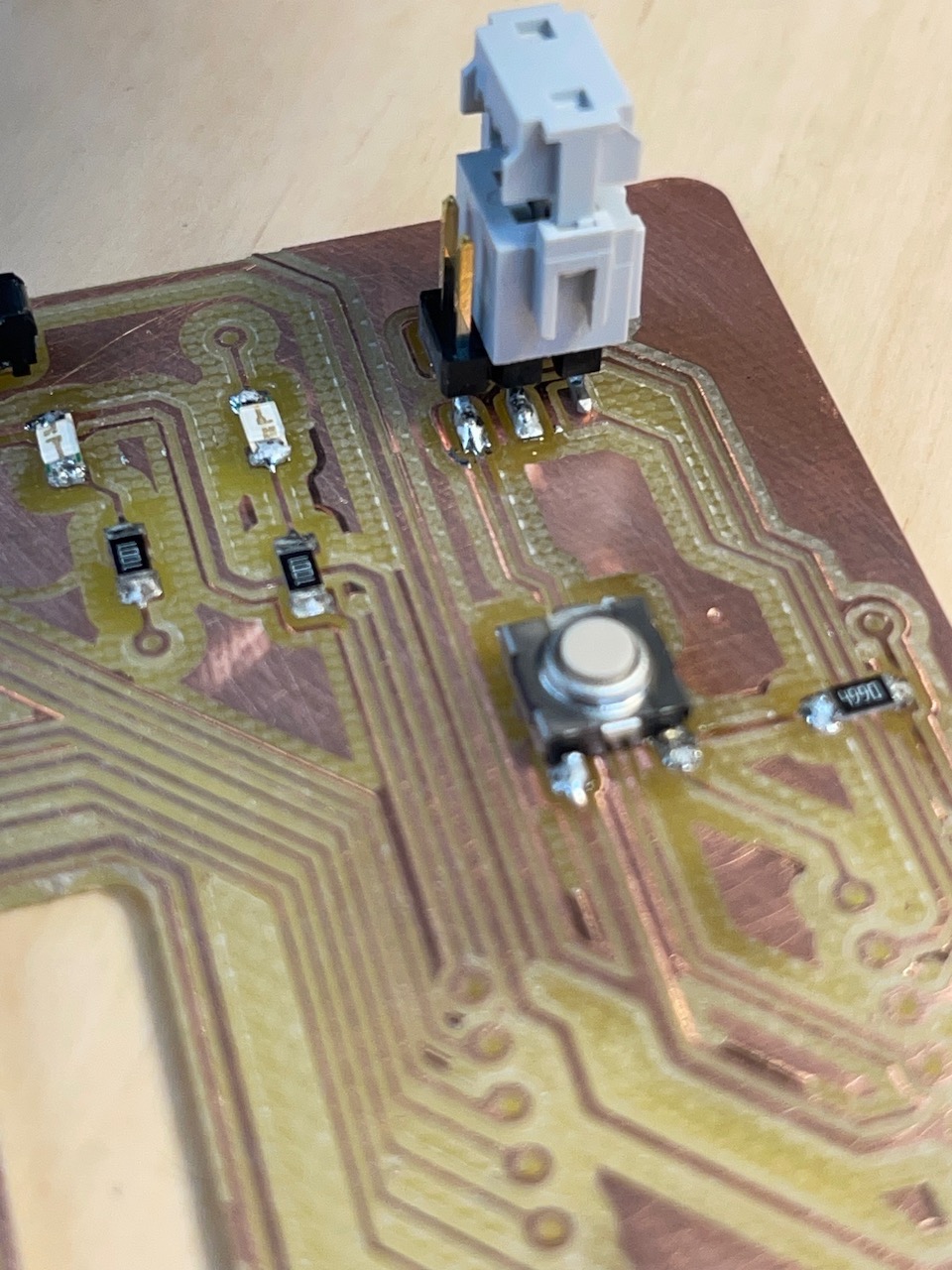
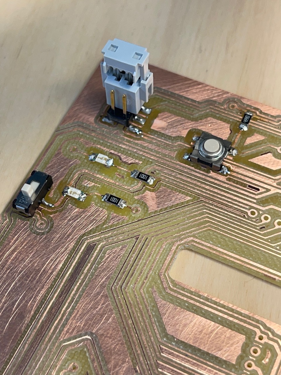
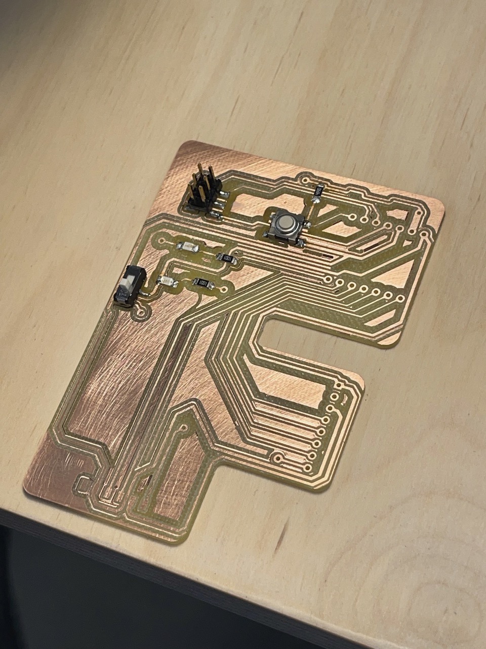
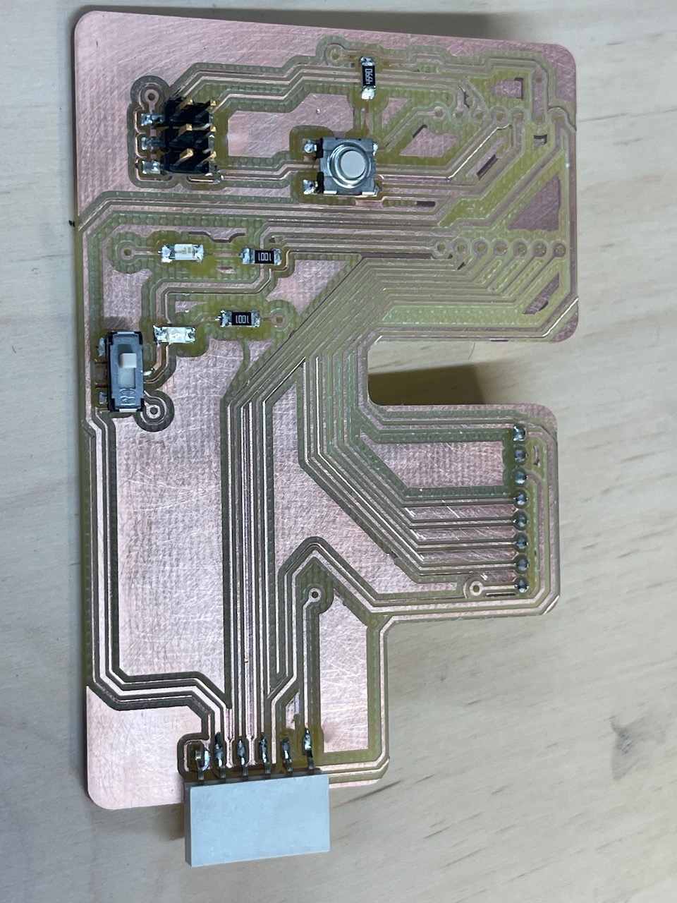
Preparing the parts to solder into the board - double-sided sticky tape and the component name
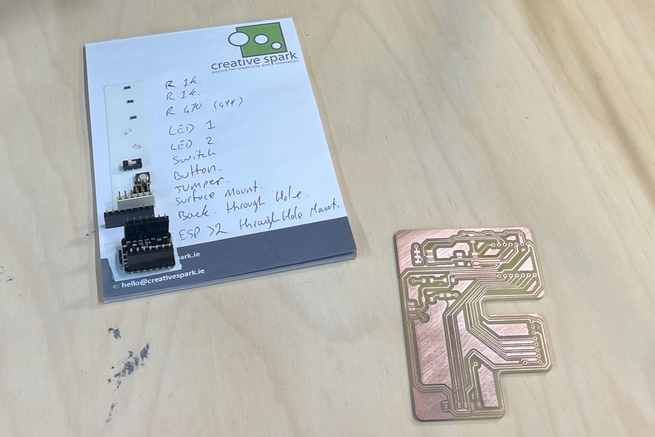
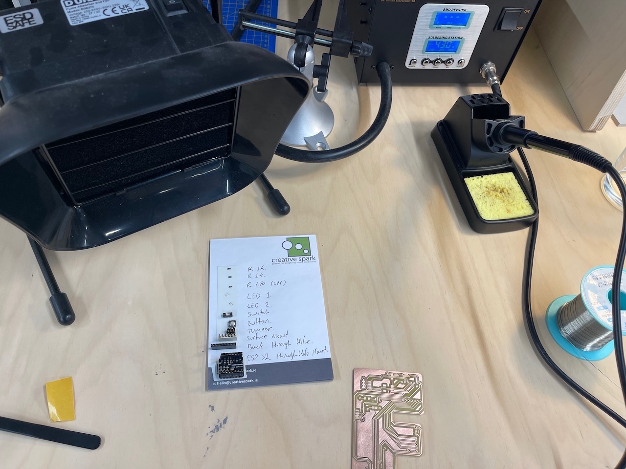
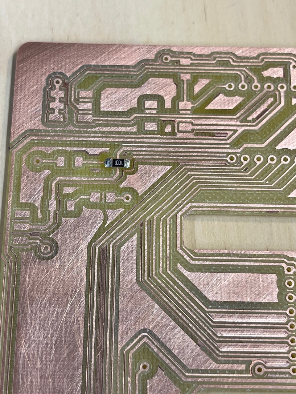
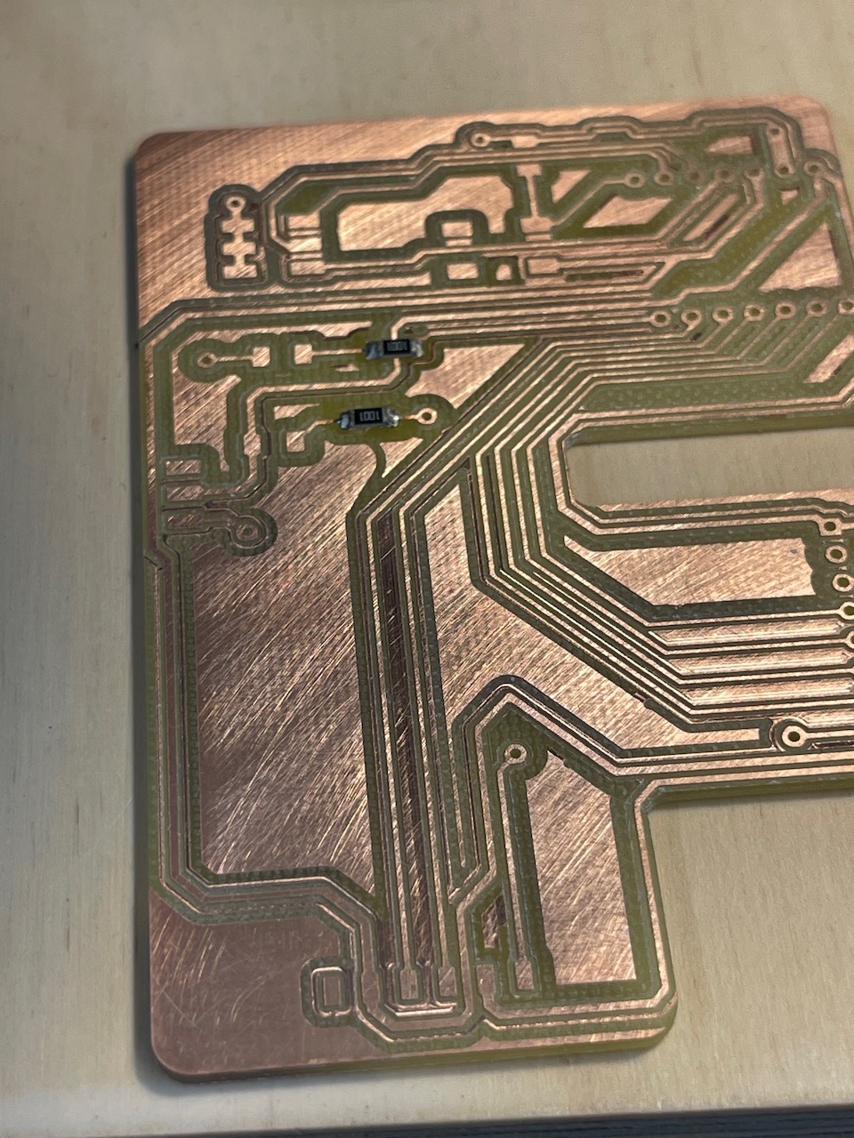
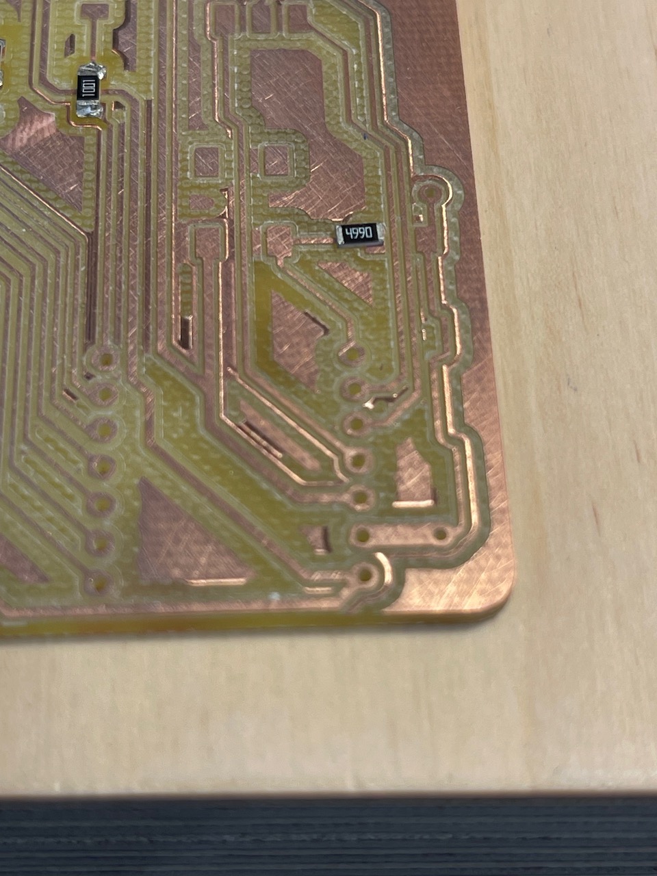
Below is the order parts were soldered onto the board
Issues I've encountered
ARGH!
What went wrong - I ran out of time this week - I had hoped to have the board milled and then solder the components on but time escaped me.
This seems to be a recurring theme for me during this course. It really does require the full 30+ hours effort every week - with a full-time job, family and everything else it is a challenge.
The mill bits that I brought back from Creative Spark Fab Lab did not fit the collet or the adapter I had at South West College.
So down to the mill to create a new adapter.
I used some 6mm bar, faced it off on the mill, used a centre drill and then used a 4mm drill to drill it out.
Then I cut down the length to make a slot which would allow the collet to be tightened around the tool.
Here is a photo of the adapter on the milling tool and in the milling machine.

 Then the bed was too low so I had to raise it up to allow the board to be milled.
Here is a photo of the board in the milling machine.
And a photo of the board after being raised - this required additional MDF to be added and then levelled to ensure the board was flat.
Then the bed was too low so I had to raise it up to allow the board to be milled.
Here is a photo of the board in the milling machine.
And a photo of the board after being raised - this required additional MDF to be added and then levelled to ensure the board was flat.
I wasn't able to push to the repo on the college network - I expect it is to do with the college firewall and IT restrictions within the college. I had to hotspot from my mobile phone to get content pushed to the website.
Bringing in components from internet downloads - I haven't nailed this yet.
I would like to be able to create my own library - however, each import into Fusion seems to be its own library.
I need to find a tutorial that will help me understand how to do this properly.
What went wrong.
Learning Outcomes
So far - I've a better grasp of Fusion Electronics and how it works - still frustrating though - especially having to push from 2D PCB to 3D PCB - but I'm getting there.
The Manufacture Workspace in Fusion to produce the cutting tool paths for the Roland MDX 540 - I did try Mods however it didn't have output for the MDX-540 so I reverted back to Fusion.
I have a good grounding in the Arduino IDE and have a good understanding of the code structure and how the types of flow required.