17. Applications and Implications
This week’s assignment is dedicated to planning the final project.
I will define the functionalities targeted, the components designed, the manufacturing processes used and the bill of materials, both raw materials and commercial parts.
The project should incorporate 2D and 3D design, additive and subtractive fabrication processes, electronics design and production, embedded microcontroller interfacing and programming, system integration and packaging
What will it do?
I intend to make a portable photogrammetry 3D Scanner.
It will capture images of an object placed on a turning plate in order to be able to reconstruct it using photogrammetry software such as Meshroom.
Additionally, it will be easily transportable and storable. On top of that, I want to make its use relatively easy for a lay person.
The first rendering of the project is hereunder.
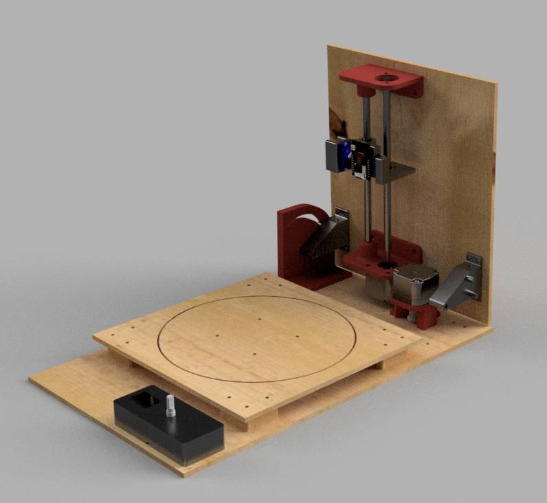
Mechanical concept
The design will be based around a turning plate and a vertical foldable plate.
On the vertical plate, an axis and lead screw are fixed an which rests a moving stage carrying the camera.
The turning plate is resting on a lazy susan and is turning thanks to a timing belt.
Motors
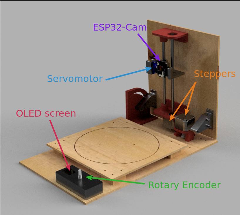
To actuate this, the project will include 2 stepper motors, one to turn the turning plate and one to control the vertical axis.
To maintain the camera on the object at an appropriate angle and to be able to capture the object at different angles, it will also include a servomotor.
Electronics
The different active components of the project.
Microcontrollers
The project include two microcontrollers :
- the ESP-Cam module : Off-the-shelf module responsible for the camera acquisition, the data exchange with the SD Card, and the Wifi server.
- The main controller board: a custom board made to communicate via USB with a computer, controlling the motors, and interacting with the user via the physical interface.
For the main controller board, I shall use a SAMD21 as they offer enough pins and natively provide a USB interface which I find very convenient.
Peripherals : Input and Output Devices
In terms of peripherals, the project will contain :
As part of the ESP32-Cam:
- a camera OV2640 (input)
- a SD Card holder (input/output)
As part of the main controller board:
- two motor drivers A4988 (output controller)
- two stepper motors NEMA17 (output)
- a servomotor SG90 or other (output)
- an OLED screen (output)
- a rotary encoder (input)
- Homing button for the vertical axis
Power Input
The power will come from a 12V DC input, but the board will also be able to be powered in 5V through USB if the stepper motors are not required (for programming and debugging).
User Interface
In terms of user interface, the user will be able to interact with the board through the OLED screen and a rotary encoder or through a web interface.
However, I have not set how much functions will be available through each interface.
Who’s done what beforehand?
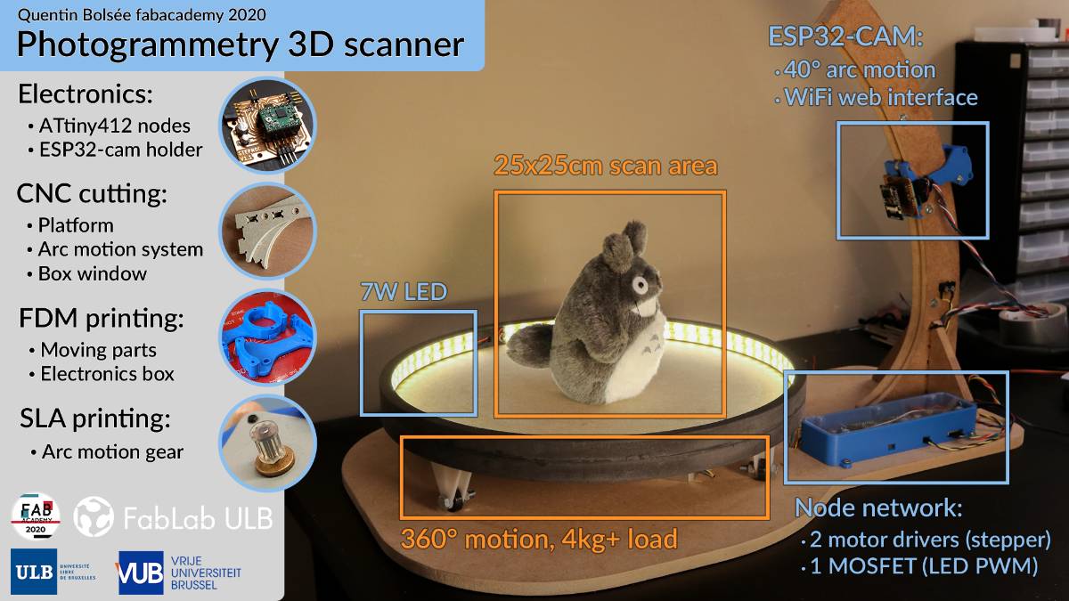
Quentin Bolsée made a 3D Scanner for photogrammetry as well, my objective is to make it more user-friendly and easier to use.
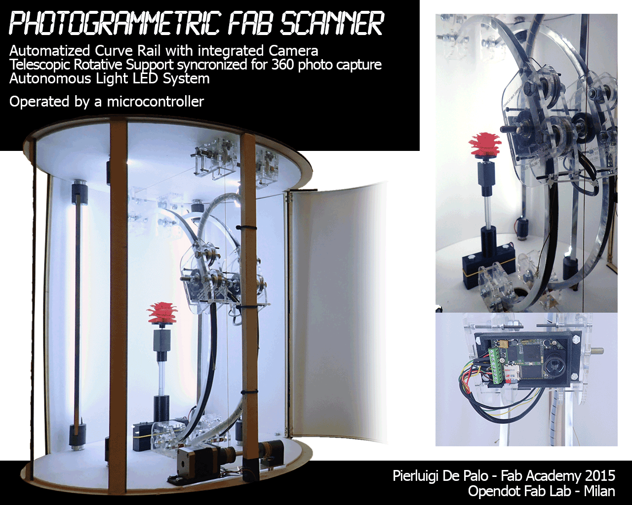
I have found another FabAcademy project but it’s not clear whether it was finished or not
I have not found photogrammetry scanners on the market but well laser scanners including some open source ones.
What will you design?
I will design most pieces to make it buildable with the lowest amount of commercial pieces possible. It will make it easier for other people to make changes in the design they will not be dependent on many commercial part.
The first rendering of the project is hereunder.
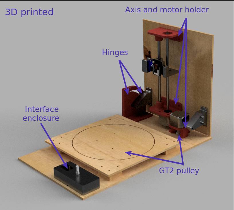
The elements designed will be :
Mechanical
- Hinges: To fold the vertical plate on the horizontal plate
- Vertical axis holders: holding the lead screw, vertical axis and the motor
- Camera stage : holding the servomotor and camera
- Turning plate
- GT2 pulley : for the turning plate and on the motor axis
- Horizontal motor holder
- Physical interface enclosure: including the OLED screen and the rotary encoder
Electronics
- Main controller based on the samd21
- General Wiring
Code
I will try to reuse as much code as possible from other projects and adapt them to my needs.
The code developped will cover:
- Web Interface
- Motor controls
- Camera controls
- Physical interface controls : OLED + Rotary encoder
- Serial USB debugging interface
Materials and Components
What materials and components will be used?
Commercial parts
I will use commercial parts for the components I cannot build myself, this includes:
- Stepper Motors
- Servomotors
- GT2 Timing belt
- Lazy susan
- Vertical axis rod
- Linear bearing for the camera stage
- Lead screw and its fixations
- Electronic components : Including SAMD21E17, 2.54mm headers, 2.54mm sockets, switch, Terminal, 1.27mm JTAG header connector, capacitors, resistors, LED, voltage regulators 3.3V and 5V, Mini USB connector, AC to 12V DC Converter
- 2 Stepper motor controllers A4988
- Oled screen
- Rotary encoder
- Wiring cables
- Screws
I will potentially add a LED ring to get consistent lighting of the scene.
Raw materials
For raw materials, I shall use :
- PLA for 3D printing
- FR1 copper plates for PCB milling
- Thin multiplex wood for laser cutting the plates
- Plexiglas for the vertical plate.
Where will come from?
Most mechanical components come from Amazon, Banggood or Aliexpress.
The electronics components and raw materials come from the fablab for the most parts except the OLED screen and the rotary encoder and the ESP cam.
How much will they cost?
| Component | Price |
|---|---|
| OLED screen | 5,69 € |
| Rotary encoder | 1,67 € |
| Stepper Motors | 15 € |
| ESP32-CAM | 11,93€ |
| Vertical Axis | 5 € |
| Lead screw | 11,59€ |
| GT2 Timing Belt | 5€ |
| PLA filament | 10€ |
| Servomotor SG90 | < 1,5€ |
| Lazy Susan/Turntable | 2,5 € |
| FR1 Board | 2€ |
Electronic components
| Component | Price |
|---|---|
| ATSAMD21E18 | 3,70€ |
| Headers | < 1€ |
| Motor drivers Pololu A4988 | 10 € |
| AC to 12V DC Converter | 5€ |
In total, the costs for the material listed above is 89.58 €.
On top of that, for the rest of the material, I account for max 20 €, including small electronics components, screws, wood and possibly PMMA.
What parts and systems will be made?
The electronic circuits, the hinges, the axis holders and GT2 pulleys, the wires will be cut and sockets put back on it, the electronics box and the overall casing.
What processes will be used?
- FDM 3D printing
- PCB milling,
- Laser Cutting
- CNC milling instead of Laser cutting if required
What questions need to be answered?
- Will the new design be robust during handling ?
- Is a controlled lighting environment required for Meshroom ? (Light tent ?)
- How many pictures are required for quality scanning ?
- How fast is the scanning performed? How fast can it be performed if improved?
- How can we transfer the images in a user friendly way to the computer?
- Is the web interface / physical interface sufficient on its own ?
How will it be evaluated?
- The first success criteria is efficacy that Meshroom is able to make a 3D model out of the pictures coming from the 3D scanner.
- The second criteria is autonomy, once started it should work independently.
- The third one is usability, can it be used and stored, relatively easily.