11. Input Devices
Assignment definition
Individual assignment: : measure something: add a sensor to a microcontroller board that you have designed and read it
Group assignment : probe an input device’s analog levels and digital signals
Research
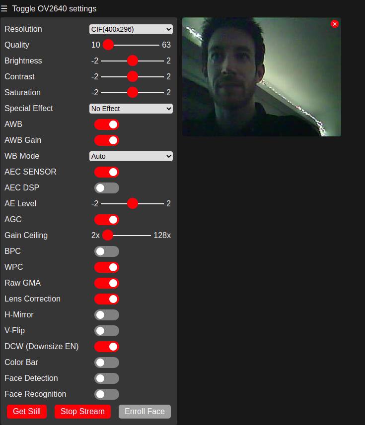
I wanted to test the ESP-CAM but it did not work out.
I wanted to test an RGB color reader, the one Neil presented was the VEML6040A3OG but we did not have it at the lab so I tried to use the one we did which is VMA325 but I could not get it to run with the demonstration code. so I had to find another solution.
Finally, I wanted to test the step response sensor because of its versatility.
Group Assignment
We tested and probed different sensors with an oscilloscope and digital analyzer on the group page.
ESP-CAM
I wanted to try the ESP-Cam and I programmed it with the programmer I made following Quentin’s instructions.
A really nice tutorial is the following.
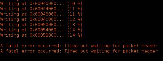
I found other people having similar looking issues but actually mine was completely different !
The problem with Quentin’s programmer is described on his page and is due to a buffer overflow.
As he mentions : “when the PC sends a sequence of exactly 64 bytes or more, the SAMD11C14 simply drops all of them with no futher explanation. This seems related to a buffer overflow, either in the bootloader or in the implementation of the Serial library in the Arduino core that comes with it.”
Anyway, after fighting for hours to get it working, I went to the lab I tried again using a FTDI adapter and it finally went fine.
RGB color reader : VMA325
For the color reader, I used the shield we had at the lab: a VMA325 however, I did not manage to get the example file to work so I had to figure it out on my own…
Understanding the sensor
I went into the datasheet of the sensor that was on the VMA325 shield and looked at the datasheet of the TCS3200.
I still did not know how to read the data on the chip but kept on trying.
I finally found a tutorial on it and realized that all the complicated code could simply be measuring the frequency using the pinpulse function. I followed the following tutorial and got it working.
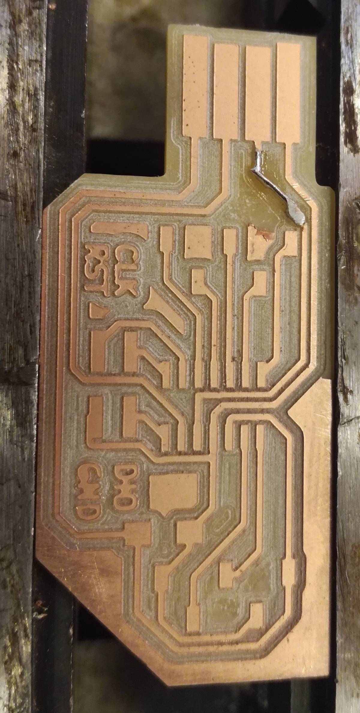
Making a board
I decided to make a board using a more complex chip than the attiny412 that I had used in the previous assignment and also having a USB port but I did not want to use an expensive microcontroller for something so simple so I went for the Samd11c14.
I started by looking at the datasheet and for the schematics and footprint in the fablibrary.
It was there so that was good. Next was designing the schematics.
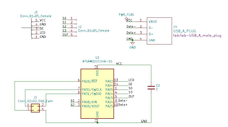
The schematics was not really complex, I just had to connect the proper connections from the shield to the Samd11c14.
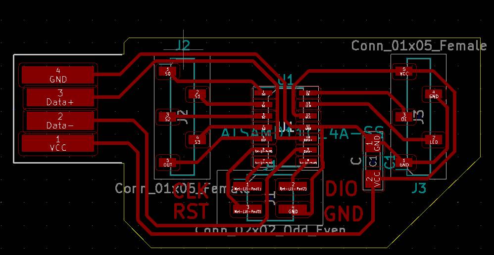
However the PCB design was much more difficult ! Because given the orientation of the shield connections, the one of the Samd11c14 and the USB port, the same connections had to go to more or less the same spot but with conflicting path.
I kept changing the assignment of the pins in the schematics and when I finally finished the design, I realized that one of the sockets was inverted… at the right distance but with the wrong orientation …
I got super frustrated but started again and I finally got to the following result.
Production
It was time for production !
Now let’s say my main lesson here is : “Don’t fix what’s not broken !”
Indeed I started by producing a board with barely any copper clearance cleaning which meant that I had to clean the copper around the USB connector by hand with a cutter, risking to damage the traces.
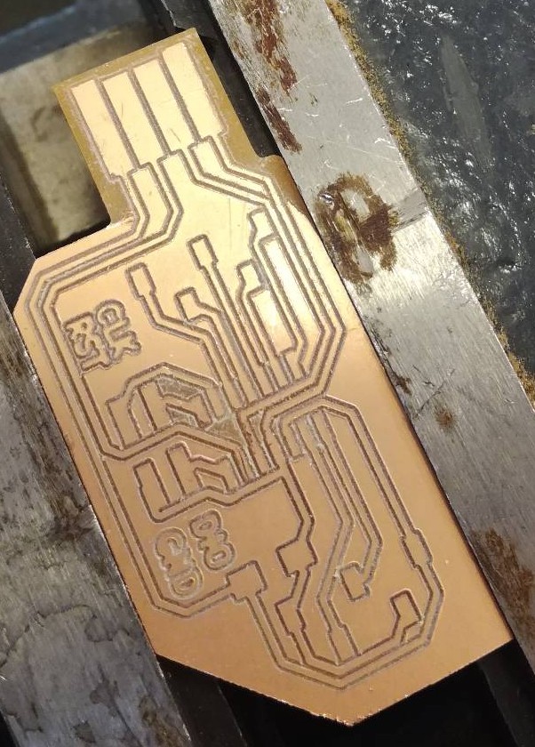
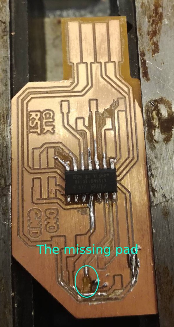
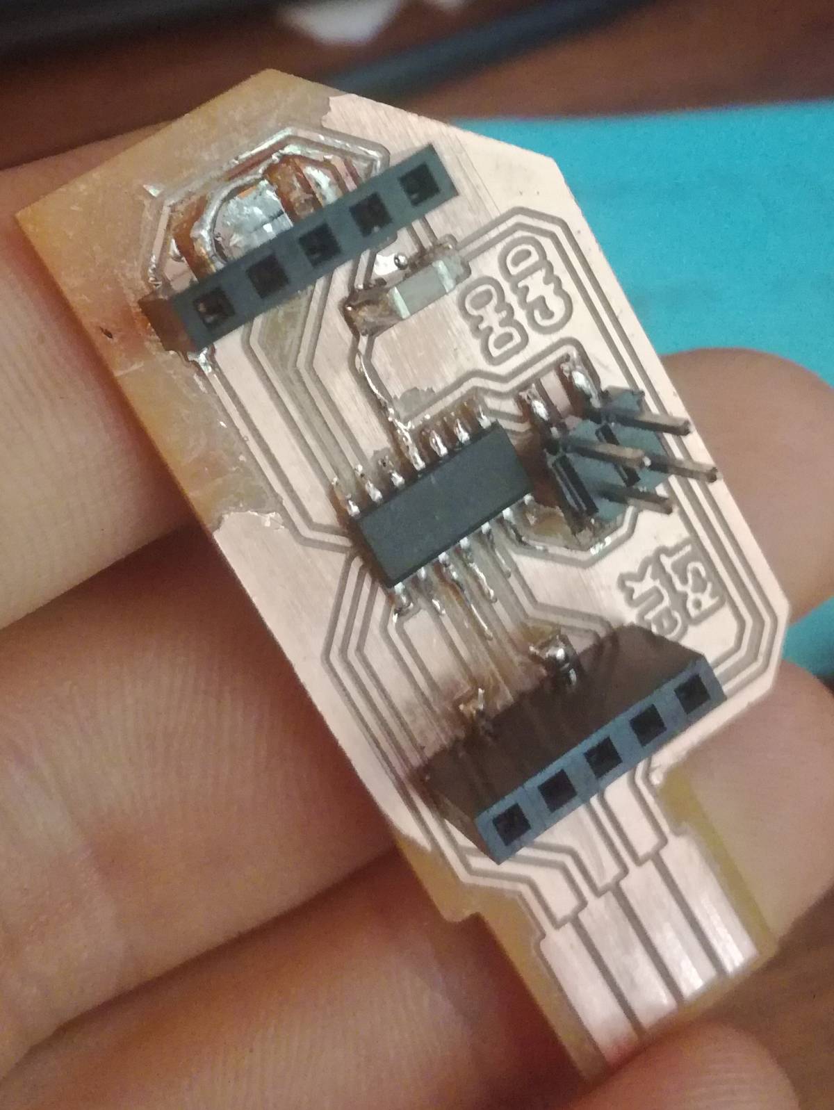
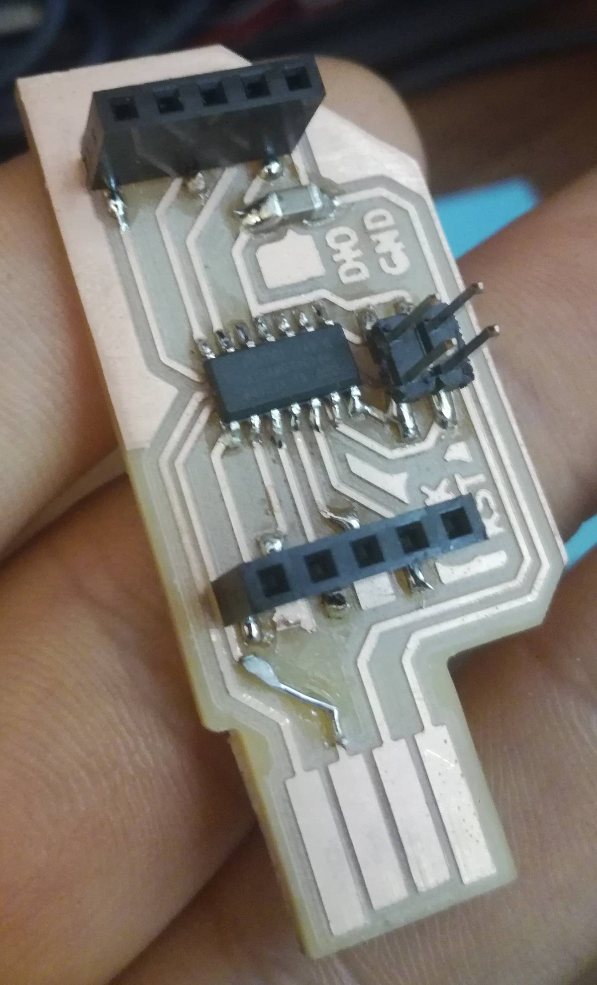
That was necessary and I did not damage it but when I started soldering, … I destroyed some pad for the socket connecting to the color sensor. I figured it was not so bad as it only controlled the LED on the sensor so I could pull it always on.
But I should not have lost faith so fast ! It worked perfectly once I loaded enough solder on it !
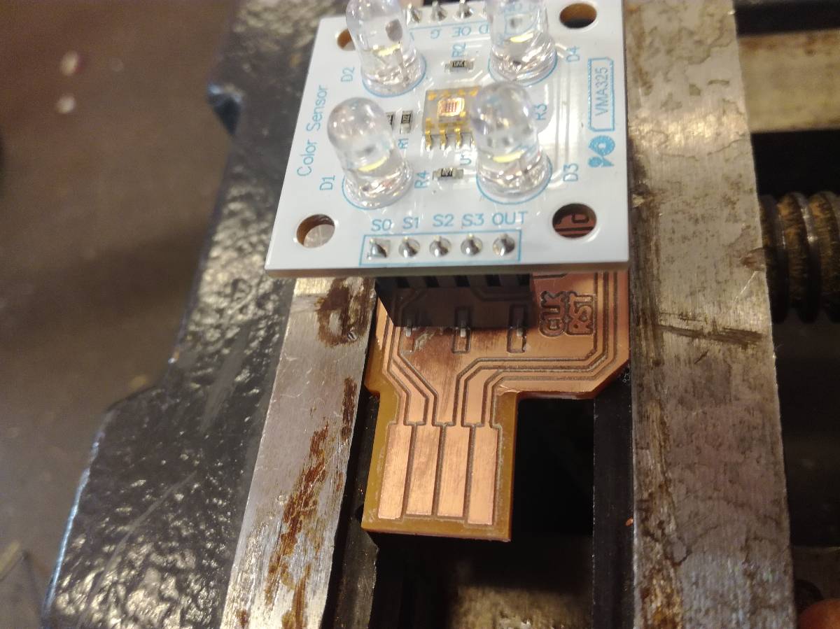
Also before soldering everything, I checked that the board fitted the sensor shield !
Well anyway, I was convinced I was about to break it so to gain time, I started milling a second one just in case. This time with a proper clearance on the copper traces !
It came out great except that I wanted to get it even cleaner and took the cutter to clean some more copper .... and I broke one of the data traces coming from the USB…
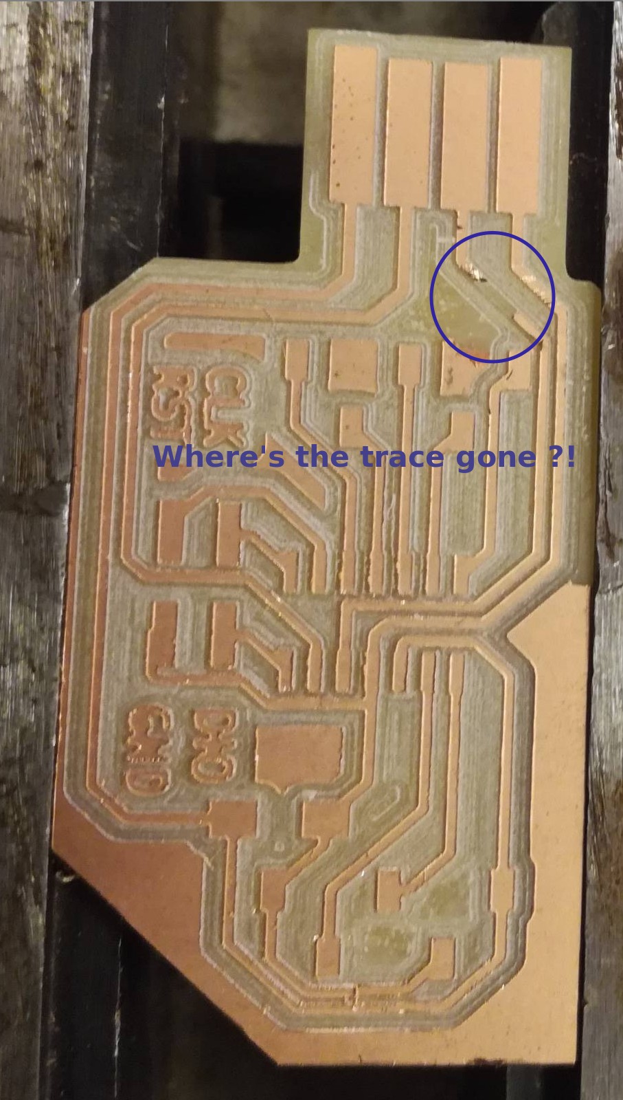
OK, it was not so bad and I had some small wire to fix it quickly so I fixed it and it went fine.
Problem is, I continued scraping my first board and broke it as well.. I fixed it too the same way and was ready to program them !
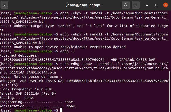
Flashing the bootloader
I programmed them using the CMSIS-DAP programmer we had at the lab with edbg to load the bootloader that would enable me to use Arduino IDE to program them and to connect directly through USB.
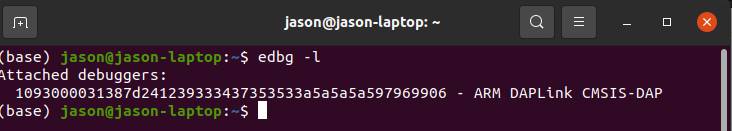
And the bootloader is succesfully installed with some permission issues.
Now was time to load my program !
Programming
I started with some simple SerialUSB.print() because I had never worked alone on a Samd11c14.
Then moved on to my Arduino code.
I wrote one function to manage the color sensing multiplexing.
void setColor(char color)
{
  if(color=='r'){
    digitalWrite(S2, LOW);
    digitalWrite(S3, LOW);
    //SerialUSB.println("Red");
    }
  else if(color=='g'){
    digitalWrite(S2, LOW);
    digitalWrite(S3, HIGH);
    }
  else if(color=='w'){
    digitalWrite(S2, HIGH);
    digitalWrite(S3, LOW);
    }
  else if(color=='b'){
    digitalWrite(S2, HIGH);
    digitalWrite(S3, HIGH);
    }
  }
Also I wanted to have a reference for the color change so I recorded the values when nothing was in front of the sensor.
int redFrequencyCenter = 993;
int greenFrequencyCenter = 1270;
int blueFrequencyCenter = 1400;
int whiteFrequencyCenter = 400;
void loop() {
// Smoothing by summing a window of 50 measurements
 digitalWrite(LED,LOW) ;
 redFrequencySum = 0;
 greenFrequencySum = 0;
 blueFrequencySum = 0;
 whiteFrequencySum = 0;
 for(int i=0;i<10;i++){
 setColor('r');
 redFrequencySum =(redFrequencySum + pulseIn(sensorOut, LOW));
 setColor('g');
 greenFrequencySum =(greenFrequencySum + pulseIn(sensorOut, LOW));
 setColor('b');

 blueFrequencySum =(blueFrequencySum + pulseIn(sensorOut, LOW));
 setColor('w');
 whiteFrequencySum = (whiteFrequencySum + pulseIn(sensorOut, LOW));
 }
 redFrequency = redFrequencySum -redFrequencyCenter +1000;
 greenFrequency = greenFrequencySum - greenFrequencyCenter+1000;
 blueFrequency = blueFrequencySum - blueFrequencyCenter+1000;
 whiteFrequency = whiteFrequencySum - whiteFrequencyCenter+1000;
And then output the result using SerialUSB following the format required by the Python script Neil had provided.
SerialUSB.print("  Red: ");
SerialUSB.println(redFrequency);
SerialUSB.print("Green: ");
SerialUSB.println(greenFrequency);
SerialUSB.print(" Blue: ");
SerialUSB.println(blueFrequency);
SerialUSB.print("White: ");
SerialUSB.println(whiteFrequency);
The sensor works well but I should do something for the LED, not sure what yet.
Finally I read the signal using Neil’s python script.
It is still a little unstable but it should be fine when calibrated.
Step response
I also looked at step response but did not take time to make a board and test it myself, that will be for another time.
What do we measure ?
The step response sensors work based on the measurement of the capacity of the surface. often it’s an open circuit and therefore the capacity would be very very small.
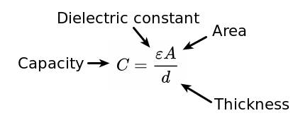
Air has a low dielectric constant and the distance between the two electrodes is high so the capacity would be very low.
What we can measure to measure the capacity is the time it takes to get charged to a certain level or the time it takes to be discharged.
To do that, one good thing to use is internal counters and clocks because with them you take advantage of the hardware and are more precise.
I haven’t gone practical with step-response but I intend to try it when I’ll have more time.